Schick Handel DMR18 User manual

DMR18
User Manual
Door Station
Please read this manual carefully before using the product you purchase, and keep it well for future
use.We reserve the right to modify the specication in this manual at any time without notice.
1 2 3
654
7 8 9
#0
*
RF CARD

1.Parts and Functions
2. Terminal Descriptions
Camera Lens
Night View LED
Speaker
Adjustable Camera
Connectiong Port
With rainy cover
350 mm
128 mm
1 2 3
654
7 8 9
#0
*
RF CARD
LCD Screen
ID Card Window
Digital Keypad
Microphone
12
3
L1
T/R -
CN-LK
T/R+
J/KMB JP-LK
Bus
SD Card Slot
EB+
EB-
N.O
LK+
LK-
+12V
L2
1 2 3
654
7 8 9
#0
*
RF CARD
12
3
12
3
• +12V:12VDCpoweroutput.
• LK-(GND):powerground.
• LK+(COM):commoncontactoftheRelay.
• NO.:normallyopencontactoftheRelay(refertoDTtechnicalguideforLockconnection
detailinformations).
• EB+:Exitbuttonconnectionport.
• EB-:Exitbutonconnectionport.
• JP-LK:Forelectroniclocksafetytypesetting(refertoDoorStationLockConnections).
• T/R-:USB-RS485communicationterminalnegative.
• T/R+: USB-RS485communicationterninalpositive.
• Bus(L1,L2):non-polaritybusline.

3.Door Station Mounting
1 2 3
4
7
5 6
Drill a hole and attach the
rainy cover to it
Attach screws to fix the
metal box
Attach the unit to the rainy
cover correctlly
Attach the baffle to protect
the unit from droping
The last view for all mounting
The view for rainy
cover after mounted
Adjust the camera angle and attach the
metal to the panel and wire correctly.
Camera
angle

4. Door Lock Connections
1. Internal Power Supply Mode
Usethepowerofthesystemtosupplyfortheelectroniclock,sothatthelockcanbe
connectedtothedoorstationdirectly,withoutanadditionalpowersupplyfortheelectroniclock.
Notethatthedoorstationcanonlyoutput12Vdcpower,thereforethekindoflockislimited.
• Theratedpowerofthelockmustbelessthan12Vdc300mAwhenusinginternalpower
supplymode
• TheGNDmustconnecttothenegativeofthelock,andtheCOMconnecttothepositive.
• Jumpersetto1-2positionforPower-to-Unlocksafetytype(Normally open mode);set
to2-3positionforPower-off-to-Unlocktype(Normally closed mode).Notethatthe
unlockrelaymodeissetontheParametertabofDTCONFIGsoftware.
• Ifdifferentunlockingtimeisneededtobeconfigured,theDTCONFIGsoftwarecanbe
usedtochangetheUnlock TimingontheParametertab(seetheprogramsection).
JP_LK
12V 300mA
Jumper set to 1-2 position
+
-+12V
LK - (GND)
LK+(COM)
N.O.
EB+
EB -
1
2
3
set to Normally open on the
Unlock Relay mode on DT-config
software.
A. Connection for Power-to-Unlock type:
12V 300mA
Jumper set to 2-3 position
+12V
LK - (GND)
LK+(COM)
N.O.
EB+
EB -
+
-
set to Normally Closed on the
Unlock Relay mode on DT-config
software.
JP_LK
1
2
3
B. Connection for Power--off-to-Unlock type:

+
+
-
-
+12V
LK - (GND)
LK+(COM)
N.O.
EB+
EB -
Remove the Jumper
set to Normally Open on the
Unlock Relay mode on DT-config
software.(default)
JP_LK
1
2
3
Note: Cut off this line when
using external power supply
+12V
LK - (GND)
LK+(COM)
N.O.
EB+
EB -
Remove the Jumper
set to Normally Closed on the
Unlock Relay mode on DT-config
software.
+
+
-
-
JP_LK
1
2
3
Note: Cut off this line when
using external power supply
2. External Power Supply Mode
Whentheelectroniclockisover12Vdc,additionalpowersupplyforthelockisneeded.
• Thepowersupplyforthelockmustbelessthan48Vdc1.5A.
• TheJumpermustberemovedwhenusingexternalpowersupply.Thedefaultsettingis
Power-to-Unlocktype(Normally open mode),ifusePower-off-to-Unlocktype,change
theUnlockRelaymodetoNormally closed mode.Notethattheunlockrelaymodeis
setontheParametertabofDTCONFIGsoftware.
• Ifdifferentunlockingtimeisneededtobeconfigured,pleaseusetheDTCONFIG
softwaretochangethesettingontheParametertab(seetheprogramsection).
C. Connection for Power-to-Unlock type:
D. Connection for Power--off-to-Unlock type:

5. Door Station Congurations
1. About room code(address):
RoomCode(alsocalledroomaddress)isacodeassignedtoeachmonitor,toidentifydifferent
monitors;eachmonitorhaveauniqueroomcodeinonebuidling.TheroomCodeisstoredin
eachMonitor’sinnerEEPROMmemory,anddoesnotloseeventhemonitorispoweroff.
2. About Debug State:
TheDebugStateisyourstartingpointforusingalltheapplicationsonDMR18.
WhenDoorStationisin
standby,press'#'key
Press"2#"keytoexitoutthedebugstate.
input'9008',theninputthe
AdminCode.(66666666by
default)
DebugStatemenuislaunched
[ 9 0 0 8 ]
Please Input Password
1 2 3
654
7 8 9
#0
*
RF CARD
>> Debug State <<
1-# Tools
0-# Redial
2-# Exits
3. About Debug Tools:
DuringworkingatDebugState,press"1#"toentertoolspage,DebugToolsoverviewsis
shownasbelow:
1. Installer Setup
2. Setup
3. Card Memory
4. Online Monitors
5. Online Devices
6. Voltage Measure
Pres NO.
to select
*Back
Tools
>> Debug State <<
0-# Redial
2-# Exits
1-# Tools

Item Submenu
1. Installer Setup
1.IDCode[1]
2.UnlockTiming[05]
3.UnlockOutput[0]
4.CardMemory[0]
5.DoorplateMode
6.AudioOptions...
7.Parameters...
8.InstallerCode...
9.Default...
2. Setup
1.Language[1]
2.ToneSelect[03]
3.ToneVolume[08]
4.UnlockCode[1111]
5.DisplayMode
6.Clock...
7.SetupCode...
8.About...
9.Default...
3. Card Manage
1.AddCard...
2.DeleteByCard
3.DeleteByM.code
4.CardsInformation
5.Format
4. Online Monitors Tosearchtheonlinemonitors,inputthemonitorcode
numbertosearch
5. Online Devices Tosearchtheonlinedoorstations.Max.4doorstation
canbesearched
6. Voltage Measure Tocheckthevoltageofthemonitor,notethatthe
monitormustbeonline.
Table1:

Basic Tools Detail:
Item Description Factory
set
IDCode
Ifonlyonedoorstationisinstalledinthisbuilding,set
to1;
Ifmultidoorstationsareinstalled,primarydoorstation
mustbesetto1,andotherslavedoorstationsmust
besetfrom2to4.Notethatmax.4doorstationsis
availableinonebuilding
[1]
Single
UnlockTiming Tosetthetimethathowlongthedoorkeepsopen
whendoorisreleased.Rangefrom01to99seconds.
[05]
5seconds
UnlockOutput Tosettheunlockmodetomatchthecorresponding
lock.Randfrom0to1 0
CardManage Tosetthecardlocation.Ifsetto0,thecardissavedin
doorstation.Ifsetto1,thecardissavedinDT-IPC 0
DoorplateMode
Tosetthecallingmode.Ifsetto0,it'stheauto
mode,thatmeansthecallingwillbeactivateddirectly
afterinputting2digitscode.Ifsetto1,it'sthemanual
mode,thatmeansyoushouldpress"#"buttonto
activatethecallingafterinputtingthecode.
[0]
Automode
AudioOptions... Tosetthetalkingmode.Ifsetto0,handsfreemodeis
activated.Ifsetto1,handsetmodeisactivated. 0
Parameters... Toshowtheparameters,pleaserefertotable2.1
InstallerCode... Tochangedoorstationadministratorcode [66666666]
Default...
Notethisoperationisirreversible. Oncerestoreis
activated,allparameterswillreturntofactorydefault
settingexcepttheinformationofaccesscard.
Table2(InstallerSetup):

Item Description Factory
set
MonitorTiming Toshowthemonitortime,Rangefrom6sto600s 30s
SwitchTiming ToshowthesurveillancetimeforeachDoorStationor
CCTVcamera.Rangefrom6sto600s 40s
WaitTiming Toshowthecallingwaittime,Rangfrom10sto600s 30s
TalkTiming Toshowthelimitationtimeoftalking,Rangefrom10s
to600s 90s
Monitor&Speack
ToenableIndoorMonitorundermonitoringstatecan
speaktoDoorStationatsametime.Ifsetto1,talk
enabled;setto0,disabled.
Monitor&Unlock
ToenableMonitorsundermonitoringstatecanopen
thedooratthesametime.Ifsetto0,unlockfunction
isdisabled;Setto1,unlockisenable;Setto2,unlock
isenableandcloseatonce;Setto3,unlockisenable
andclosein5s.
[1]
RingNumbers
Toshowringtimeswhendoorstationcallsmonitor.4
optionsforchoice.Ifsetto0,ringonce.Ifsetto1,ring
twice.Ifsetto2,ringthreetimes.Ifsetto3,cyclering
[1]
NameListDisplay
Mode
Toshowthenamelistdisplaymode.Ifsetto0,it'sthe
DT-Configdisplaymode.Ifsetto1,it'stheSimulate
displaymode
[0]
WorkingMode Toshowtheworkingmode.Ifsetto0,it'stheapartment
systemmode.Ifsetto1,it'sthevillamode. [0]
Table2.1(Parameters):
Note:thissectionissetonDT-Congsoftware,formoredetailinformations,pleaserefertothe
DT-Congsoftwareuserinstructions.

Item Description Factory
set
Language
Tochangelanguage.thecodeformatis4digits.Pleaserefer
topart5,section10(changedoorstationlanguage)formore
detailinformations.
01
ToneSelect SelectthechimeofDoorStationincallingwaitstate,12
chordtunesareavailable,keyin01to12toselect. 03
ToneVolume Adjustthetonevolumefordooorstationincalling.Rangfrom
01~15 08
UnlockCode TochangeunlockcodeinCommonCodeUnlockmode,in
4-digitsformat.1111isthedefaultunlockcode. [1111]
DisplayMode
ToselecttheDoorStationscreenmenu.Ifsetto0,the
screendisplaysthevisitor'simagewhentalking.Ifsetto1,the
screendisplaysiconswhentalking.
[0]
Clock...
Tosetdateandtime.
Dateformat:ifsetto0,dateformatisDD/MM/YY,ifsetto
1,dateformatisMM/DD/YY.
Timeformat:ifsetto0,timeformatis24hourstandard.Ifset
to1,timeformatis12hourstandard.
SetupCode TochangetheProgramCode. [88888888]
About...
1.Hardwareversion---ToshowtheDoorStation(including
ACS)hardwareinformation
2.Softwareversion---ToshowtheDoorStation(including
ACS)softwareinformation
3.ManufactureDate---Toshowthemanufacturingdate
4.DialingCounts---Toshowthecalloperationcounts
5.CallsCounts---Toshowtheestablishedcallingcounts
6.UnlockCounts---Toshowtheunlockoperationcounts
7.StandbyVoltage---Toshowthevoltagethatthedoor
stationinstandby.
8.WorkingVoltage---Toshowthevoltagethatthedoor
stationinworking.
9.VideoStandard---PALorNTSCstandard
10.UI_CODE---ToshowtheUIbytecountsandcheckbox
11.MCM-VER---ToshowtheversionandlanguageforMCM
12.Updated---ToshowtheupdatedtimeforUI
Default... RestoreallSetupparameterstofactorydefaultsetting,Please
notethatthisoperationisanirreversible
Table3(Setup):

Item Description Factory
set
AddCard... Toaddtheusercard
DeleteByCard Todeletecardbyusercard
DeleteByM.code Todeletecardbyroomcode
CardsInformation Toshowtheinformationsaboutcards
Format Toformatinformationsaboutcards
Table4(CardMemory):
4. Calling and Unlock Operation:
TheDMR18doorstationisadigitalstationwith320*240pixelsLCDscreen,colorCCD
camera,nightviewLED,anddigitalkeypad.
VisitorscancalltheapartmentbydialingtheFlatCode(apartmentnumber)onthekeypad.
Iftheydon’tknowtheFlatCode(apartmentnumber),theycansearchthenamelistonthe
screen.Ifthedoorstationisinstandby,visitorsneedtopress'9#'todisplaytheusernamelist.
Press"#"keytoscrollnext/lastpage.andusekey1to8keyoneachpagetocallthedesired
at.
ResidentscanopenthedoorbyusingtheiruniqueUnlockCode(four-digitPINcode).Ifthe
doorstationisinstandbymode,press'#'key,theninputthefour-digitunlocktoopenthedoor.
Pleaserefertopart5,section7(Howtousecodeunlockfunction)formoredetailinformation.
5. About Default Set:
TheDefaultSetisveryimportant.Whenthedoorstationmissupthesettingsinanyway,
themostquicklyandeasywaytosolvetheproblemistoactivatethedefaultsettingondoor
station.Thedefaultsettingsalreadyhavealltherightsettingsforone-buildingsystem,that
meansthesystemwillworknormallywithoutanyadditionalsettings..
Note:Ifthedoorstationworksasapartmentsystemmode,input01~32tocalltherelevant
monitor.Ifthedoorstationworksasvillamode,input01tocallthemonitorswhichitscodeis
from00~15.Input02tocallthemonitorswhichitscodeisfrom16~31.pleaserefertotable
2.1(workingmode)

InDebugState,press'1#'
key
InToolsmenu,press'1'
key
InputInstallercode(66666666
bydefault),thenpress"#"tosave
Press'9'key,a
passwordwillbeasked.
>> Debug State <<
0-# Redial
2-# Exits
1. ID Code.[1]
2. Unlock Timing[05]
3. Unlock Output[0]
4. Card Memory [0]
5. Doorplate Mode
6. Audio Options ...
7. Parameters ...
8. Installer Code...
Press No.
to select
*Back
Installer
Setup
9. Default
1-# Tools
1. Installer Setup
2. Setup
3. Card Memory
4. Online Monitors
5. Online Devices
6. Voltage Measure
Pres NO.
to select
*Back
Tools
*Back
[ - - - - - - - - ]
Please Input Password
# Save
9. Default...
Press“#”,Input“8002”,then
inputSetupCodeorAdmin
Code(88888888or66666666by
default)
Press“2”toentertone
selectitem.
6. Change Ring Tone:
Thereare12differentringtones,IfdoorstationrunsasDebugState,youcanpress[1#]-->
[2]Setup-->[2]ToneSelecttoentertonesettingpage.IfitrunsasNormalState,followthese
steps:
Input2digitsnumber,
thenpress“#”tosave
thesetting
[ 8002 ]
Please Input Password
1 2 3
654
7 8 9
#0
*
RF CARD
1. Language [1]
3. Tone Volume[03]
4. Unlock Code[1111]
5. Display Mode
6. Clock
7. Setup Code
8. About
9. Default
Press No.
to select
*Back
Setup
*Back
[ - - ]
( 01~12)
# Save
2. Tone Select [03]
2. Tone Select [03]
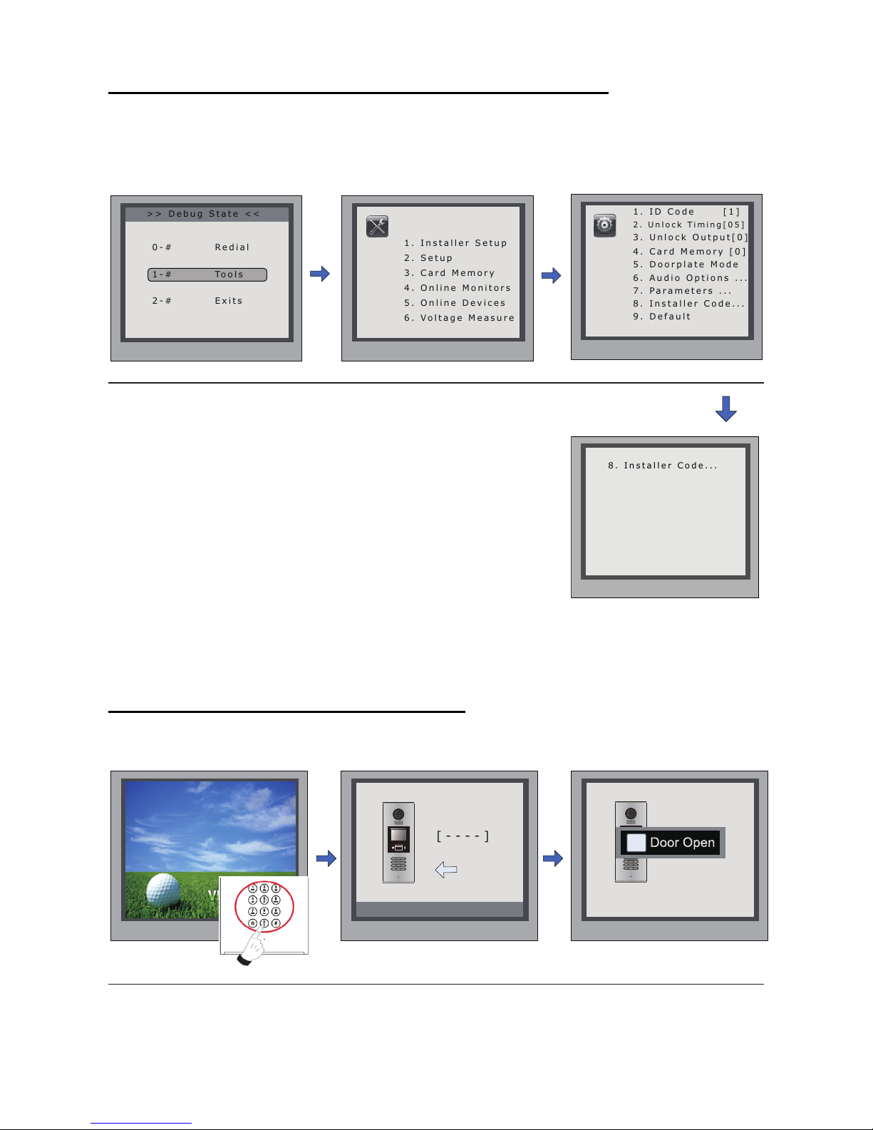
7. Change Installer Code(administrator password):
TheInstallerCodeisthepasswordtoaccessthedoorstationdebugState.Thedefault
InstallerCodeis'66666666'.NotethatiftheDefaultSethavebeenactivated,theInstallerCode
willbesettodefaultvalue.
8. How to use code unlock function:
Pleaserefertothefollowingoperations:
>> Debug State <<
0-# Redial
2-# Exits
1. ID Code [1]
2. Unlock Timing[05]
3. Unlock Output[0]
4. Card Memory [0]
5. Doorplate Mode
6. Audio Options ...
7. Parameters ...
9. Default
Press1~9
to select
*Back
Installer
Setup
1-# Tools
8. Installer Code...
1. Installer Setup
2. Setup
3. Card Memory
4. Online Monitors
5. Online Devices
6. Voltage Measure
Pres NO.
to select
*Back
Tools
*Back
[ - - - - - - - - ]
( * * * * * * * *)
# Save
8. Installer Code...
InDebugState,press'1#'
key
InputanewInstallerCodeand
thenpress'#'keytoconrm
press'1' press'8'
[ - - - - ]
Please Input Password
1 2 3
654
7 8 9
#0
*
RF CARD
1 2 3
654
7 8 9
#0
*
RF CARD
[8017 ]
iDoor Open
WhentheDoorStationisin
standby,Press“#”
Ifveriedcorrectly,
dooropen
Input4digitsUnlockCode
directly

Press“#”,Input“8002”,
theninputSetupCodeor
AdminCode(88888888or
66666666bydefault)
Press“4”toenterunlock
codeitem.
9. Change Unlcok Code:
IfdoorstationrunsasDebugState,youcanpress“1#”toactivateToolsMenu,thenselect“2”
toentersetuppage,thenselect4item.IfitrunsasNormalState,followthesesteps:
[ 8002 ]
Please Input Password
1 2 3
654
7 8 9
#0
*
RF CARD
1. Language [1]
2. Tone Select [03]
3. Tone Volume[03]
5. Display Mode
6. Clock
7. Setup Code
8. About
9. Default
Press No.
to select
*Back
Setup
*Back
[ - - - - ]
( * * * *)
# Save
4. Unlock Code[1111]
4. Unlock Code[1111]
Input4digitsnumber,
thenpress“#”toupdate
10. User Card Management:
ThissectionexplainshowtocongurethekeyfobfunctiononDMR18,Thekeyfobisusedto
openthelock.Total1000keyfobscanberegisteredwithonedoorstation.Whenswipingthe
fobtothedoorstation,thedistancemustbelessthan3centimeter.
KeyFobsmustberegisteredontheDoorstationthatcanbeusedtoopenthedoor.
Register the Key Fobs:
AlltheregisteredkeyfobsarecalledUserCards/UserKeyFobs.Newfobs/cardsneedto
beregisteredonebyonetotheDoorstationtobecomeavalidUserCard/UserKeyFob;and
everyUserCard/UserKeyFobisrelatedtoacertainMonitorAddress(Flatcode).
WhentheDoorstationisstandby,press[#]-->[9008]-->Password([66666666bydefault])
togetintotheDebugModeMenu,thenPress[1#]-->[3]CardManage-->[1]AddCardtoget
intotheAddCardpage.Pleaseseethefollowings.

EnterAddCardmenu,and
RoomCodeisasked.
InputRoomCode Readthecardtobe
authorized
Delete user cards:
Delete By Card:
InDebugState,Press[1#]-->
[3]CardManage-->[2]Delete
ByCardtoenterDeletebyCard
page.asshownontheright,
thenshowthecardsyouwantto
deleteonebyone.
2. Delete By Card ...
* Back # Save
Show The Card
2. Delete By Card ...
* Back # Save
User
Card
C a r d numbs:15977131
Show The Card
RegisteredUserCards/KeyFobscanbedeletedfromtheDoorstation,oncedoingthedelete
operation,thecard/keyfobscannotopenthedooranymore.Theycanalsobere-registered
againtobecomeavalidUserCard/UserKeyFob.TherearetwowaystodeleteUserCards/
UserKeyFobs:
1.Deletebycard:showtheunwantedcard(s)whentheDoorstationisinDeleteCardMode
2.Deletebyroomnumber:deletealltheregisteredUserCardsrelatedtothatroomnumber.
1. AddCard ...
* Back # Save
Please Input Room Code
[ - - ]
1. AddCard ...
* Back # Save
Show the card
[ 0 1 ]
1. AddCard ...
* Back # Save
[ 0 1 ]
C a r d numbs : 15977131
Show The Card
User
Card
3. Delete By M.code
* Back # Save
Please Input Room Code
[ - - ]
3. Delete By M.code
* Back # Save
U p d a t e d
[ 0 1 ]
InDebugState,Press[1#]-->
[3]CardManage-->[3]Delete
ByM.CodetoenterDeleteby
M.Codepage.asshownon
theright,thenInputtheRoom
Code,press“#”toconfirm;all
associatedcardswillbedeleted.
Delete by Room Number:

Card information:
Format:
EnterCardInformationpage,andthe
screenwilldisplaytheauthorizedUser
Cardscount,andcardreadaccess
eventscount.
EnterCardFormatpage,apassword
willbeasked,input8digitsinstaller
password(66666666bydefault),then
press"#"keytosave,formatoperation
isactivated.allcardinformationwillbe
cleared.
4. Cards Information
* Back # Save
Card Count: 1000
5. Format
* Back # Save
Please Input Password
[ - - - - - - - - ]
11. Change Door Station Language:
It'sconvenienttochangetheuserinterfaceforDMR18.JustputtheconglestotheSDcard
andbymeansofthedigitalkeypadofdoorstation,only30secondsisneededtoupdate.
L1
T/R -
CN-LK
T/R+
J/KMB JP-LK
Bus
Insert SD card
SD Card Slot
EB+
EB-
N.O
LK+
LK-
+12V
L2
12
3
12
3
Step 1: Insert the SD card which is
containedconglesintotheSDcardslot
whereisatthebackofthedoorstation.
Refertotherightdiagram.
Step2:
IfdoorstationrunsasDebugState,youcanpress“1#”toactivateToolsMenu,select“2”to
entersetuppage,thenselect1item.IfitrunsasNormalState,followthesesteps:

Language code number:
[8017 ]
iDownload
[ 8002 ]
Please Input Password
1 2 3
654
7 8 9
#0
*
RF CARD
2. Tone Select [03]
3. Tone Volume[03]
5. Display Mode
6. Clock
7. Setup Code
8. About
9. Default
Press No.
to select
*Back
Setup
*Back
[ - - - - ]
( Code Number)
# Save
1. Language
4. Unlock Code[1111]
1. Language [1]
Press“#”,Input“8002”,then
inputSetupCodeorAdmin
Code
Press1 Input4digitscodenumber,
Refertothetable.
Whenthedoorstationoutput
alongsoundDI...,thatmeans
UIupdatingisnished.
8101: English
8102: French
8103: Spanish
8104: Italian
8105: German
8106: Dutch
8107: Portuguese
8108: S-Chinese
8109: T-Chinese
8110: Greek
8111: Turkish
8112: Polish
8113: Russian
8114: Slovakia
8115: Hungray
8116: Czech
12. Search online door stations and monitors:
“OnlineSearch”isaveryusefulfunctionthatcanhelptheinstallertoeasilycheckthe
connectivityofalltheMonitors.Pleasenote,Onlinedoesnotmeanviatheinternet.Please
refertothefollowings:
>> Debug State <<
0-# Redial
2-# Exits
* Back # Save
[DS1 ] : Online
[DS2 ] : Fail
[DS3 ] : Fail
[DS4 ] : Fail
5. Online Devices
1-# Tools
1. Installer Setup
2. Setup
3. Card Memory
4. Online Monitors
5. Online Devices
6. Voltage Measure
Pres NO.
to select
*Back
Tools
InDebugState,press'1#'
key
Press'5'key Checkdoorstations
connectionstatus
Check online door stations:

>> Debug State <<
0-# Redial
2-# Exits
* Back # Save
(Search Range)
[ - - ] ~ [ - - ]
4. Online Monitors
* Back # Save
[ 01 ] Online
[ 02 ] Online
[ 03 ] Online
[ 04 ] Fall
[ 05 ] Online
4#.Online Monitors
1-# Tools
1. Installer Setup
2. Setup
3. Card Memory
4. Online Monitors
5. Online Devices
6. Voltage Measure
Pres NO.
to select
*Back
Tools
InDebugState,press'1#'
key
Press'4'key Input2digits
monitorcode
SearchRange:inputthemonitoradress.Forexample,
inputtherangefrom01to05.Youwillseetheconnection
statusoftheselectedmoinitors.
13. Namelist function:
DMR18isdesignedtohavedigitalkeypadandbigTFTscreen.Itsnamelistwasshownon
thescreenandcustomercandothecallingoperationthroughthedigitalkeypadguidedby
Namelistonthescreen.2typesofnamelistcanbeshownonthescreen:DT-Congnamelist
andSimulatenamelist.
Enter namelist page:
Check online monitors:
Send namelist to monitors
Press'9#'instandbymodetodisplaytheusernamelist.Press"#"keytoscrollnext/lastpage.
andusekey1to8keyoneachpagetocalltheatyouwant.PleaserefertotheDT-Cong
softwreuserinstructionsforcongurethenamelist.
Thenamelistcanbesenttomonitorsbydoorstationdirectly.Connectthedoorstationand
montiorscorrectlytothesystem.Thenpress#8012instandbymode,andinputpassword
(66666666bydefault)tosendnamelisttoallthemonitors.

6. Specication
●Power supply: DC24V(Powered by DT-DPS)
●Camera Lens : 1/4 ACS 4T image sensor with DSP processor
●Power consumption: Standby 3W;Working status 9W
●Screen: 3.5 inch TFT
●Resolution: 320(R, G, B)X240 pixels
●Video signal: CCIR/EIA Optional
●Wiring: 2 wires, non-polarit

DT-ENG-DMR18-V1 2011S0621
Table of contents
Languages:
Other Schick Handel Intercom System manuals


