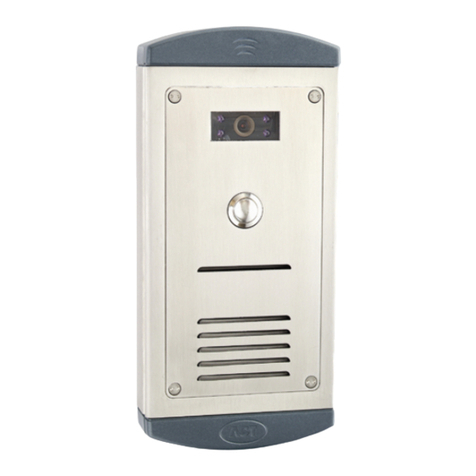
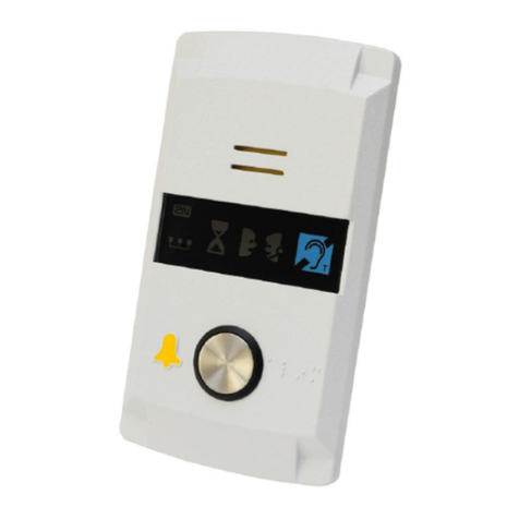
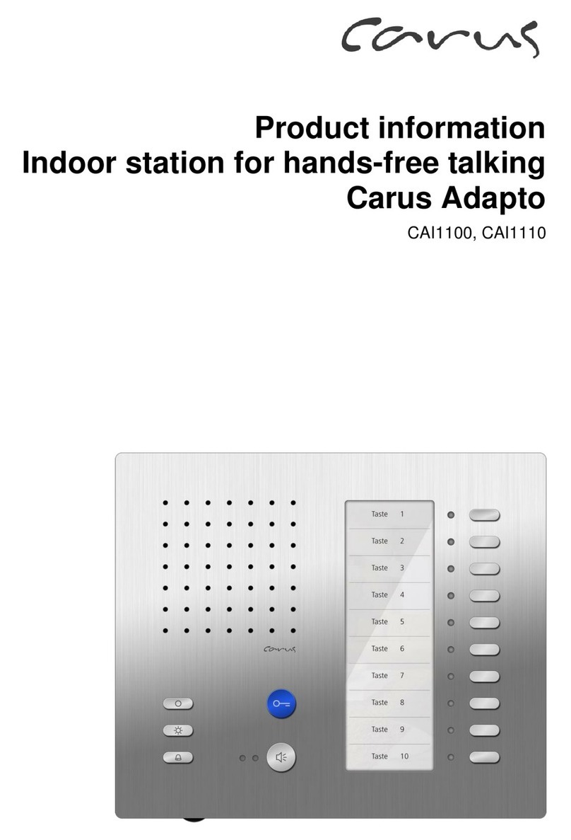
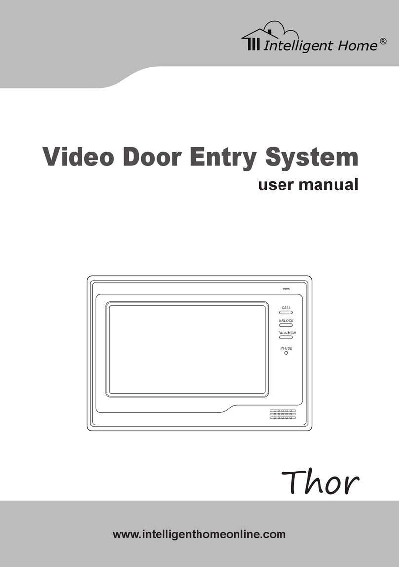
Schick Handel DT596/ID User manual

2 -Wire Intercom System
DT596(F)/ID User Manual
DT596/ID DT596F/ID
DT-ENG-596(F)ID-V1 110S923
RF CARD
RF CARD

Rainy Cover
DT596/ID
DT596F/ID
Side View Mounting box
RF CARD
RF CARD
Camera Lens
ID card window
Speaker
Indicator
Indicator
Nameplate
Call Button
Microphone
90 mm
28 mm
176 mm
220 mm
119 mm
ID card window
Camera Lens
Speaker
Nameplate
Call Button
Screws for panel
mounting
Microphone
RF CARD
RF CARD
1.Parts and Functions
2.Terminal Descriptions
BUS
PL
S1+ S2+ S-
MIC adjustment
(Lock Control Jumper)
Door Station Code DIP
Main Connect Port
SPK adjustment
1 2 3 4
ON DIP
JP/LK
RS485 Connect Port
1 2 3
-1-

JP/LK(Lock Control Jumper):
Doorstation Code DIP:
RS485:
MIC
SPK
Main Connect Port:
•
3.Door Station Mounting
adjust camera angle
1 2
43
Drill holes in the wall to match the size of
screws and attach the rainy cover to the wall.
Attach the panel to the rainy cover Use the screwdriver and the screw
to fix the panel
Connect the cable correctly and adjust
right angle for camera
DT596/ID Mounting
-2-

DT596F/ID Mounting
1
90mm
174mm
52mm
2
43
Drill a hole in the wall to match the size of the
mounting box and attach to the wall.
Attach the panel to the mounting box and
use screws supplied to fix the panel
Place name label
Connect the cable correctly and adjust
right angle for camera
adjust camera angle
PS
Adjusting Camera Angle
-3-

Placing Name Label
RF CARD
4. System Wiring and Electric Lock Connection
Basic Connection
-
+
AC~
monitor
DPS PS4
L1 L2 PL S1+ S2+ S-
-4-

Electric Lock Connection
Door Lock Controlled with Internal Power
Unlock Mode
Door Lock Controlled with Dry Contact
Unlock Mode
EB
*
LOCK
BUS PL S1+ S2+ S-
LOCK
2nd
1ST
2nd
EB
*1ST
Jumper position in
Connect two locks
2-3
1 2 3
EB
*
LOCK
BUS PL S1
+
S2
+S-
Jumper position in
Connect one lock
2-3
1 2 3
-5-

Unlock parameter setting(set on monitor)
LOCK
BUS PL S1
+
S2
+S-
Take off the Jumper
POWER
SUPPLY
LOCK
BUS PL S1
+
S2
+S-
Take off the Jumper
POWER
SUPPLY
LOCK
-6-
Manual
Monitor
Monitor
Memory
Playback
Album User Setup
09/30/2010 Thu.16:41
Close
Intercom Multimedia
?About
H/W : DT14-CT a1.3
S/W: V17.11.418.00
Local addr: ---
Unlock timing: ---
Video standard: -
UI-CODE: ---
MCM-VER.: ---
Updated: ---
Home
Installer
setup
Caliber
TouchScreen
Code Number:[----]
[0010]#:Remove all remote control
[0011]#:Add remote control
[8000]#:Set as master unit 0
[8001]#:Set as slaver unit 1
[8002]#:Set as slaver unit 2
[8003]#:Set as slaver unit 3
[8004]#:Set as guard unit
[8005]#:Set as not guard unit
[8006]#:Panel on as slaver unit called
[8007]#:Panel off as slaver unit called
[8008]#:Date format:MM/DD/YYYY
[8009]#:Date format:DD/MM/YYYY
[8010]#:Set lock mode to 0
[8011]#:Set lock mode to 1
[8021]~[8029]
#Set the lock time of 1~9s
Multi language settings:
---
1
4
78
0
9
6
5
23
Cancel
Installation settings:
1.Touch item on main
menu page.
2.Touch the screen anywhere
and hold for 2s.
3.Touch Installer setup item
4.A digital keypad and setting
instructions will be showed.

Multi Door Stations Connection
85~260VAC
DPS PS5
monitors
L1 L2 PL S1+ S2+ S- L1 L2 PL S1+ S2+ S-L1 L2 PL S1+ S2+ S-L1 L2 PL S1+ S2+ S-
123 4
ON
123 4
ON
123 4
ON
123 4
ON
1# Camera
ID=00
ID=10
ID=01ID=11
2# Camera3# Camera4# Camera
DBC4
A B C D
BUS
-7-

Basic IN-OUT Wiring Mode
Multi Monitors Connection
Code=0, DIP-6=off
Code=14, DIP-6=off
Code=15, DIP-6=on
1 2 3 4 5 6
ON
1 2 3 4 5 6
ON
1 2 3 4 5 6
ON
monitor
monitor
monitor
123 4
ON
ID=00
85~260AC
DPS PS5
RF CARD
-8-

5.DIP Switches Setting
DIP Switches Settings of Monitor
DIP Switches Settings of Door Station
Setting Item Bit state Descriptions
1234
ON
1234
ON
1234
ON
1234
ON
1234
ON
1234
ON
ON(1)
=
OFF(0)
=
ON
ON
-9-

6. ID Card Registration
Introduction:
MASTER CARD ADD
MASTER CARD DELETE
Bit state User Code Bit state User Code Bit state User Code
1 2 3 4 5 6
ON
1 2 3 4 5 6
ON
1 2 3 4 5 6
ON
1 2 3 4 5 6
ON
1 2 3 4 5 6
ON
1 2 3 4 5 6
ON
1 2 3 4 5 6
ON
1 2 3 4 5 6
ON
1 2 3 4 5 6
ON
1 2 3 4 5 6
ON
1 2 3 4 5 6
ON
1 2 3 4 5 6
ON
1 2 3 4 5 6
ON
1 2 3 4 5 6
ON
1 2 3 4 5 6
ON
1 2 3 4 5 6
ON
Bit state Setting Bit state Setting
1 2 3 4 5 6
ON
1 2 3 4 5 6
ON
-10-

Delete User Cards:
Access Initialization (delete all user cards):
red
red
red
red
red
red
(on)
(on) (on) (on)
(blink) (off)
(off)
(off)
(off)
(off) (off)
(off)
blue
blue
blue
blue
blue
blue
beep+,beep
beep+,beep+
beep+
beep+
beep,beep+
beep,beep,
beep,beep,
beep+
MASTER CARD
DELETE
MASTER CARD
DELETE
MASTER CARD
DELETE
MASTER CARD
ADD
MASTER CARD
ADD
red red red
(on) (blink) (off)(off) (off) (off)
blue blue blue
beep+,beep beep+ beep,beep+
MASTER CARD
ADD
MASTER CARD
ADD
2.Control two locks
-11-
Add User Cards:
red red red
(on) (blink) (off)(off) (off) (off)
blue blue blue
beep+,beep beep+ beep,beep+
MASTER CARD
ADD
MASTER CARD
ADD
1.Control one lock(the rst lock)

Authorize master cards:
red red red
(on) (off) (on) (off)(on) (on)
blue blue blue
beep+,beep beep+ beep+
MASTER CARD ADD
MASTER CARD DELETE
MASTER CARD ADDMASTER CARD DELETE
7.Unlock Operations
(red)
ON
(blue)
OFF
Beep+
(red)
OFF
(blue)
ON
Beep+
Blue LED lights up
(during relay2 operation)
Red LED lights up
(during relay1 operation)
Unlocking of ID Card
-12-

8. Precaustions
9. Specications
-13-

10. Cables Requirements
When Monitor quantity < 20
Cable Usage A B C
When Monitor quantity > 20
Cable Usage A B C
The farest monitor
B
A
C
DPS PS5
DBC/DBC-4
monitor
monitor
monitor
with two or four monitors
RF CARD
-14-

The design and specications can be modied without notice to the user. Right to interpret
and copyright of this manual are reserved.
DT-ENG-596(F)/ID-V1 110S926

Anleitung für DT27/25/692SD/TD7
Videostationen
ManualDT69SD/TDXXSerie-DE/Schick2010

Vorsichtsmassnahmen/Fehler :
Bitte schützen Sie Ihre Anlage vor Erschütterungen
Bitte reinigen Sie alle Komponenten mit einen Bauwolltuch (keine Chemikalien)
Es kann zu Bildverzerrungen kommen wenn andere elektrische Geräte zu nah sind
Bitte schützen Sie alle Geräte vor Feuchtigkeit zu hohen Temperaturen und Staub
Befestigen Sie den Monitor in einer Höhe von ca. 160 cm um eine optimale Sicht auf den Monitor zu gewährleisten.Befestigen
Sie die mitgelieferte Halteplatte mit den Schrauben an der Wand und hängen Sie den Monitor ein.
Anleitung für Innenstation DT27 SD /TD7
Die optimale Montagehöhe für Ihren Monitor beträgt 145-160 cm . Befestigen ie die Halteplatte an der Wand der Monitor wird
nun von oben eingerastet!

Innenmonitor Teile und Funktionen
Bedienanleitung
Betätigen ie den Bildschirm oder drücken ie den Menü Knopf ( ensortaster unten rechts) , der Bildschirm öffnet sich und es
wird der Kalender angezeigt Datum Wochentage und die Uhrzeit .Betätigen ie den Bildschirm erneut und es erscheint das
Hauptmenü auf den chirm.
•
Manual Monitor : Zur manuellen Auswahl Ihrer Außenstation es können hier bis zu 4 Türstationen ausgewählt und
einzeln selektiert werden
•
Auto Monitor : Der Es werden alle Verfügbaren Außenstation oder/ und Kameras angezeigt im einstellbaren
Intervallen

•
Intercom : Bei dieser Funktion erreichen ie das Interkom- Menü
o
Interkom by Namlist : Hier werden alle Namen im Haus wenn programmiert
(nicht mit Jeder Türstation möglich)
angezeigt
sind einzeln anwählbar
o
Inner Call : hier können alle lave - tationen in einer Wohnung angewählt werden (Je nach Türstation 4 oder
max. 16 tück)
o
Direkt Call Guard Unit: ie können im ystem einen Pförtner oder Wachmann anlegen den ie direkt
anwählen können
•
Memory Playback: Anzeigen der gespeicherten Bilder (immer 4 tück) Verfügbare Funktionen löschen, vor/zurück ,
alles löschen, ins Hauptmenü
•
Album : Hier können Photos die auf der D Karte (nicht im Lieferumfang /-2GB) gespeichert sind angezeigt werden .
Über den Ikon Multimedia >>Album Options kann die Abspieldauer der Albumanzeige eingestellt werden
•
User etup : Hier könne Einstellungen wie Lautstärke der Klingel /Nachtklingel Lautstärke / Klingelton Außenstation
Intercom* und Türklingel*
( *noch nicht verfügbar) /
Telefonwahlfunktion
(derzeit noch nicht freigeschalten)
•
chließen des Monitors
About : Hier ereichen sie die Experten Einstellung und die Anzeige der Systemdaten (siehe unten )
Klingelton Einstellung :
Im Menü User etup haben ie die
Möglichkeit den Klingelton für die
Außenstation für die Interkom Funktion
und für die Türklingel eizustellen . ie
haben hier 12 unterschiedliche Melodien
zur Verfügung . Dur berühren der
entsprechenden Melodie auf den
Bildschirm wird selbige abgespielt . Dur
betätigen des Exit & ave Ikons wird
die Melodie ausgewählt und
abgespeichert
This manual suits for next models
1
Table of contents
Languages:
Other Schick Handel Intercom System manuals
