Schick Handel DT6910 User manual

2-wire Intercom System
DT6910 user manual
DT-ENG-6910-V1 100S204

PRECAUTIONS
●
●
●
●
●
●
●
●

CONTENT

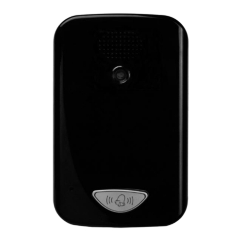
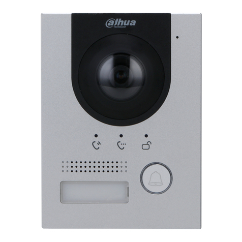
The DT 591 is a special design for the DT 2-wire system:
• Full matel cover with backlight nameplate
• 4 Door cameras connection
• Directly connect 2 separate electronic locks, unlock time controlled by Monitor
Name
1. Door Camera DT591-1-

• Lock Control Jumper: To congure the electronic lock safety type; set the jumper in 1-2 position for Power-
to-Unlock type(pulse activated electronic lock), set the jumper in 2-3 position for the Power-Off-to-Unlock
type(electromagnetic lock). Remove the jumper if using external power supply for the lock.(the power+ will be
connected to the PL on the Main Connect Port)
• Camera Code DIP: To set the code for the door camera, total 4 cameras can be connected in the system; See
chapter 18 Multiple Door Camera Connection -- Note 3.
• Main Connect Port: To connect the bus line and the electronic locks.
• BUS: Connect to the bus line, no polarity.
• PL: External lock power input, connect to the power positive(power +).
• S1+, S2+: Lock power(+) output, to connect 2 electronic locks.
• S-: Lock power(-) output, connect to the power(-) input of electronic locks(only when using the camera to power
the locks, if using the external power supply for the locks, the S- will not be connected)
2. Electronic Lock Connections
The standard inner power lock connection, use the Camera power to supply the lock, no need for external power
supply. In this way, the Lock Control Jumper and Unlock Mode in the monitor need to be set: for Power-to-Unlock
type electronic lock, set to position 1-2 and Unlock Mode 0; for Power-Off-to-Unlock type electromagnetic lock, set to
position 2-3 and Unlock Mode 1(see chapter 16 Unlock Mode Setting).
-
+
Electronic lock
-
+
ElectronMagnetic lock
-2-

Directly connect 2 electronic locks to the door station and use the Camera power to supply the locks. There are 2
separate unlock icons on Monitor for opening each lock. Note that the 2 locks should be the same safety type.
Use external power supply to power the electronical locks, in this way, wide range lock from 5V to 24 V electronic
locks can be used in the system. Note that in this case, the Lock Control Jumper is removed in both lock type.
-
+
-
+
Electronic lock
lock #2
lock #2
lock #1
lock #1
-
+
ElectronMagnetic lock
-
+
-
-
+
+
Electronic lock
-
+
ElectronMagnetic lock
Adaptor
-
+
-3-

1 2 3 4
1 2 3 4
Lock Power supply: 12Vdc, 500mA(supplied by system)
Power Consumtion: 1W in standby, 12W in working
NO, COM exchange contact: Max. 24V dc 3A
Unlocking time: 1 to 9 seconds, set by Monitor
Working temperature: -5ºC +40ºC
-4-
3. Door Camera Installation

-5-
4. Indoor Monitor5. Monitor Mounting
145~160 cm
1. Use the screws to x the Mounting Bracket on the wall.(tting accesories includes a Bracket (Two
4X25 screws are needed for fastening the Mounting Bracket), Special 2 wire cables to connect
with Monitor)
2. Wire the system correctly(see the later connection chapter) then hang the Monitor on the
Mounting Bracket rmly.

-6-
6. System Connection(Basic)
-
+
AC~
● Note 1: When only one Door camera installed, set both the bit-1 and bit-2 to OFF state.
● Note 2: Mount the DPS and PS4 side by side on the DIN nail or on the wall.
● Note 3: See chapter 3 Electronic Lock Connections for detail information.
● Note 4: The bit-1 to bit-5 DIP switches are for Monitor address settings when multiple Monitors
installed, the bit-6 is for video impedance setting. When there is only one Monitor installed, set all
the bit-1 to bit-5 to OFF state, and set the bit-6 to ON position.
● Note 5: Connect the DPS to the output of PS4, non-polarity connection.
● Note 6: Conncet to the AC Mains electricity, 100~240 V AC.
● Note 7: Non-polarity 2 wire bus cable. See Table 2-1 for cable usage information.
Cable type Max. distance(meters)
Table 2-1

-7-
7. Monitor Operation IntroductionIn this Monitor, all the icons on the screen has a corresponding button, and each button has a
corresponding LED indicator; the LED indicator also has a state-sencitive feature for easy operation.
When the screen showing the menus, press
the corresponding buttons to enter the sub
menu.
When the screen showing the item which
have variable setting values, press the
corresponding buttons to increase the value
in sequence.
When the screen showing operation icons,
press the corresponding buttons to execute
the operation.
Ooutdoor Tone -- 01
Intercom Tone -- 05
Monitor Time -- 2min
Advanced Set...
Exit
1

8. Talk/Unlock Operation2. Press TALK ◄ Button, you can talk with the visitor for 90 seconds. During talking state, press
the TALK ◄ Button again to end the conversation. If nobody answers the phone, the screen will
be turned off automatically after 30 seconds. If the system connects two or more Monitors, when
any Monitor starts to talk, the other Monitors will be automatically shut off.
1. When visitor presses the Call Button on the Outdoor Station, the monitor rings, at the same
time, the screen displays the visitor image.
1
1
3. During the conversation, press UNLOCK
▲ Button to unlock the door. (if 2 locks
connected to the Door Camera, press ▲
Button to show the 2 lock icons, press a lock
button to open the matching lock)
1. Unlock icon
2. Camera switch icon
3. Exit icon
4. Talk icon.
5. Setting icon.
-8-

-9-
9. Ring Tone Setting10. Monitor Time Setting
Ooutdoor Tone -- 01
Intercom Tone -- 05
Monitor Time -- 2min
Advanced Set...
Exit
Ooutdoor Tone -- 01
Intercom Tone -- 05
Monitor Time -- 2min
Advanced Set...
Exit
► Button
▼
►Button
►Button
●
Monitor Time
►Button
◄ ButtonSetup
► Button to enter the main menu,
◄ Button Setup
►
Button
▲Button toOutdoor Tone
▼Button to
Intercom Tone
1. Current time.
2. Current date.
3. Current weekday.

11. Time Setting
Slave Addr Set -- 0
Guard Unit Set -- 0
Date/Time Set...
Information...
Exit
Ooutdoor Tone -- 01
Intercom Tone -- 05
Monitor Time -- 2min
Advanced Set...
Exit
◄ Button
◄ Button / ●
▲Button /▼ Button to increase /
decrease the current number, ●
2008
▲/▼ Button to
increase /decrease the current number, ●
● ButtonDate/Time Set
►
Button ► Button
◄ Button Setup ◄
Button to enterAdvanced Set 12. Screen Setting
► Button
S c r e e n M o d e :
Ratio:
Ring Volume:
Talk Volume:
-10-
1
Normal
16:9
Ring Volume 5
Talk Volume 8
Exit
User
Brightness 5
Colour 6
Exit

13. Slave Address Setting
Slave Addr Set -- 0
Date/Time Set...
Guard Unit Set -- 0
Information...
Exit
►
Button ►
Button
◄ ButtonSetup
▲ Button 1/2 Camera
◄ Button to Advanced Set
Ooutdoor Tone -- 01
Intercom Tone -- 05
Monitor Time -- 2min
Advanced Set...
Exit
-11-
14. Restore to Default
H/W ver A1.1 S/W ver V8.0
Voltage 15.8V
Manufacture DM 1
Restore to default
Exit
Date/Time Set...
Information...
Exit
Slave Addr Set -- 0
Guard Unit Set -- 0
Restore
to default
Exit
►
Button
◄ Button
Setup Advanced
Set
►Button
►Button

15. Intercom Function I n formation...
▲Button and hold for 3 seconds to enter the
Unlock setting page.
TouchPad Set
Unlock Time:
Unlock Mode:
RTC Sync Command:
-12- 16. Unlock Mode Setting
H/W ver A1.1 S/W ver V8.0
3 seconds
Voltage 15.8V
Manufacture DM 1
Restore to default
Exit
RTC Sync Command
Unlock Mode -- 0
Exit
TouchPad Set -- On
Unlock Time -- 3
Redial
EXIT
Inner Call
Guard Unit Call
Intercom Call
Exit
EXIT
TALK
Press ● Button again to redial.
Press ►Button to cancel the call.
When the Monitor is in standby, press ● Button
to start intercom menu.
Press ▼ Button to select Inner Call. (The
Intercom Call and Guard Unit Call function
are reserved.)

17. Multiple Monitors Connection
AC~
● Note 1: The Slave Addr Set on the 1# Monitor set to 0.
● Note 2: The Slave Addr Set on the 2# Monitor set to 1.
● Note 3: The Slave Addr Set on the 3# Monitor set to 2.
● Note 4: The Slave Addr Set on the 4# Monitor set to 3.
● Note 5: The bit-1 to bit-5 of all the Monitors are set to OFF. The bit-6 set to OFF for 1#, 2# and
3# Monitors.
● Note 6: All the connectors must use In-Out connection.
● Note 7: The bit-6 of the 4# Monitor must set to ON state.(the bit-6 of all the Monitors should be
set to OFF state except the last one which is at the end of the bus line).
-13-

18. Multiple Monitors Connection
AC~
● Note 1: The settings for all the Monitors are the same as chapter 16 Multiple Monitor
connections.
● Note 2: All the connectors must use In-Out connection.
● Note 3: The Address for each doorstation must be set. Set bit-1 = bit-2 = OFF for the 1# Door
Camera; set to bit-1 = ON, bit-2 = OFF for 2# Camera; set to bit-1 = OFF, bit-2 = ON for 3#
Camera; set to bit-1 = ON, bit-2 = ON for 4# Camera.
1
2
3
4
When multiple Door Cameras are installed, each Door
Camera can connect its own electronic locks, and the
Unlock operation will only unlock the lock connected to
the calling Door Camera.
When monitoring, all Door Cameras can be swiched from
one to another. On the monitoring or talking state, press
the 1 icon on the screen, will show the Camera select
menu, than select a Camera.
-14-

19. Extend Functions
-15-

20. Specifications●
●
●
●
●
●
●
●
-16-

DT-ENG-6910-V1 100S204
Table of contents
Other Schick Handel Intercom System manuals
