SCHIEBEL LK Series User manual

Operation manual for linear units type LK
DS-ENGLISH-SCHUB-LK-V1.00-2020.03.23
SEC-DS-ENGLISH-SCHUB-LK-V1.00-2020.03.23
Operation manual for linear units type LK
1 General
Type LK linear units are offered in different variants, see Table 1. These are mounted together with electric
open/close or modulating actuators, of the series CM, on valves which require a linear positioning movement.
These linear units convert the torque output from the actuator into an axial force through a ball screw drive.
Not only is a higher control accuracy allowed, but also a longer lifetime is provided with the use of a ball screw
drive. The combination of actuator and linear unit, is based on the required thrust and the necessary stroke.
Type Actuator Output
flange Stroke Output
thread Pitch Factor (Nm
kN )Weight [kg]
LK50 CM03 G0/F10 50mm M20x1,5 5mm/rev 1,06 12,3
LK100 CM03 G0/F10 100mm M20x1,5 5mm/rev 1,06 15,0
LK120 CM06 G0/F10 120mm M20x1,5 5mm/rev 1,06 19,2
CM06 G 1
2/F14 120mm M36x3,0 5mm/rev 1,06 23,6
Table 1: Technical data linear units
2 Structure
Figure 1 shows e.g. an CM03 actutator with mounted LK linear unit. The linear unit itself consists essentially of
a solid cast housing, a mounted spindle nut and a non-rotating spindle, see Figure 2. To prevent contamination
by dusty ambient air and to ensure the mechanical protection, the linear unit is completely sealed with O-rings
at the output.
Figure 1: CM03-Actuator with mounted LK100 linear unit
1

Operation manual for linear units type LK
DS-ENGLISH-SCHUB-LK-V1.00-2020.03.23 3 Packaging, transport and storage
Table 2: Parts list of the linear unit
Part no. Description
1 Output flange
2 O-Ring
3 Groove nut
4 Bearing plate
5 Axial deep groove ball bearing
6 Bearing ring
7 Intermediate flange
8 O-Ring
9 Housing tube
10 O-Ring
11 Base flange
12 O-Ring
13 Wiper
14 Feather key
15 Ball screw spindle
16 Feather key
17 Coupling and output shaft
18 Cup spring
19 Spindle pin
20 O-Ring
21 Spindle pin ring nut
22 O-Ring
3 Packaging, transport and storage
See chapter „Packaging, transport and storage“ in der standard user manual.
4 Assembly and disassembly of linear units on valves
In the following two subsections, the procedures for assembly and disassembly of linear units on valves are
explained step by step.
4.1 Security and assembly instructions
The device may only be mounted and commissioned by qualified personnel!
Qualified personnel within the meaning of this operating manual are persons who are familiar, with as-
sembly, commissioning and operation of this product, and have the required appropriate qualifications
for this activity.
For assembly and disassembly of the linear unit, the pipes where the valve is installed on
have to be depressurized! If the actuator is removed from the linear unit, the position of the
valve stem won’t be fixed anymore and will be lost due to the linear units non self locking
property.
The linear unit has end stops on both end positions. Do not move against the end stops in
electrical operation! The end limits of the actuator must be set accordingly!
3

5 Commissioning
Operation manual for linear units type LK
DS-ENGLISH-SCHUB-LK-V1.00-2020.03.23
Never bring the valve cone with excessive force in the CLOSED position. This can damage the high-
quality sealing edges.
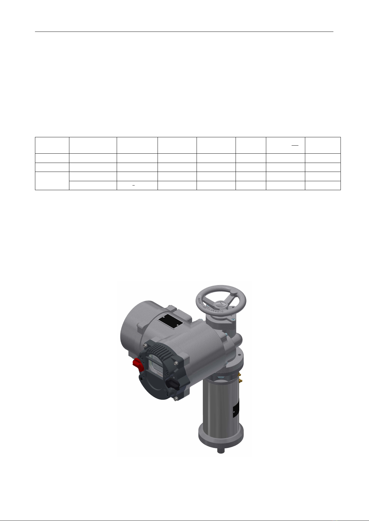
4.2 Assembly
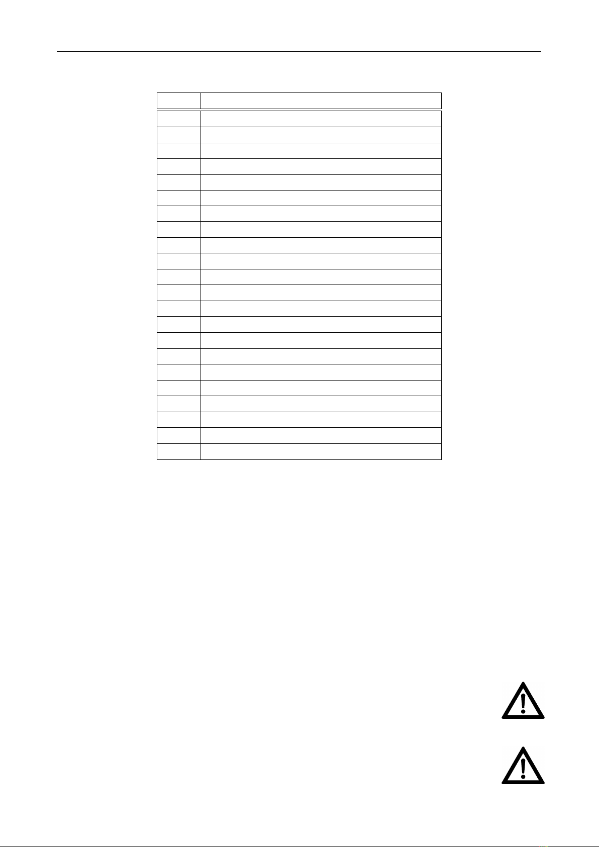
1. Check that the actuator flange, the linear unit flanges and the valve flange match.
2. Thoroughly clean screw-on surfaces and bare parts on actuator, linear unit and valve.
3. Lightly grease the connections of the actuator, the linear unit and the valve.
4. Grease the spindle of the linear unit.
5. Move the valve cone in the CLOSED position.
6. Turn the spindle nut until the linear unit is in a central position.
7. Mount the linear unit on the valve and tighten the screws crosswise. The coupling between the linear unit
and the valve will be connected later.
8. Mount the actuator on the linear unit and tighten the screws crosswise.
9. Extend the spindle by rotating the handwheel until the coupling of the linear unit and the valve fit together.
10. Connect the coupling between linear unit and valve.
11. Use the handwheel to move the linear unit to a center position, to prevent accidental damage to the valve
during startup.
4.3 Disassembly
1. If the valve is fully closed, move the valve cone to about ten percent OPEN position
2. Loosen the screws between the output flange of the actuator and the linear unit and dismount the actua-
tor.
3. Open the spindle coupling between the linear unit and the valve.
4. Loosen the screws between the output flange of the linear unit and the valve.
5. Dismount the linear unit from the valve.
5 Commissioning
See chapter „Commissioning“ in the standard user manual.
6 Maintenance
Pay attention to increased running noises, occur on them, grease the two lubrication nipples of the linear unit
to lubricate the bearings and the spindle guidance.
Regularly check the fixing screws between the actuator, the linear unit and the valve for firm hold, if necessary
tighten them with the torques specified in chapter „Installation instuctions“ of the standard user manual.
6.1 Moving interval
The linear unit should be actuated at least every 3 months.
6.2 Greasing intervall
Every 6 months the linear unit should be re-greased via the greasing nipples .
4

Operation manual for linear units type LK
DS-ENGLISH-SCHUB-LK-V1.00-2020.03.23 7 Lubricant recommendation
7 Lubricant recommendation
Lubricating grease DIN 51825-K(P) R -40
i.e. Water-repellent complex grease based on Al-soap with high resistance to acids and alkalis:
Ambient Temperature: -40 bis +85 ◦C
Worked penetration 0,1 mm: 310 - 340
Dripping point: ca. 260 ◦C
NLGI-Class: 1
acid-free, not or only slightly reactive with water
5
This manual suits for next models
3
Table of contents
Other SCHIEBEL Industrial Equipment manuals