Schier Products PROSPECTOR Series Installation guide
36
16 gallons
36
22 gallons
36
35 gallons
36
52 gallons
36
125 gallons
36
275 gallons
127(6
Schier solids interceptors are not to be installed in any other manner except as shown. Consult local
codes for separate trapping requirements, cleanout locations and additional installation instructions.
6KHHW'HVFULSWLRQV
Sheet #1 - Series overview and Warranty information
Sheet #2 - General installation guidelines and Operation/Maintenance guidelines
Sheet #3 - Below Grade installation guidelines (PS-35, PS-50, PS-125, PS-275)
Sheet #4 - Below and Above Grade installation guidelines
Sheet #5 - TeleGlide Riser installation guidelines (PS-35, PS-50, PS-125, PS-275)
Sheet #6 - TeleGlide Riser installation guidelines (PS-15, PS-25)
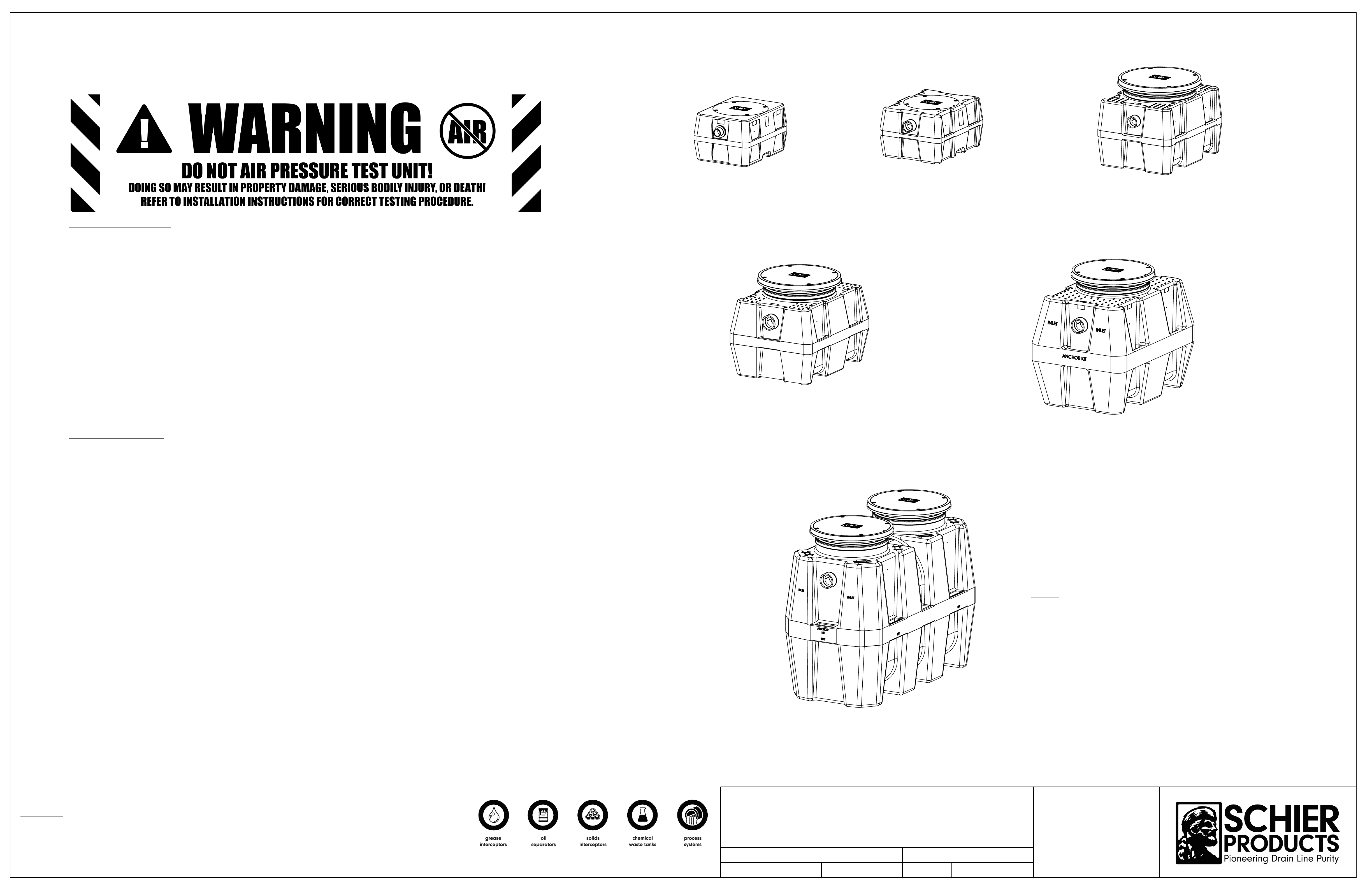
/HDN6HDO7HVWLQJ
'2127$,57(6781,7257(/(*/,'(5,6(56<67(0'RLQJVRPD\UHVXOWLQSURSHUW\GDPDJHSHUVRQDOLQMXU\RUGHDWK
Base Unit:
To perform a leak/seal test on the base unit, cap/plug all plumbing connections, remove the cover, and fill the unit with water just above the
highest connection. Inspect unit and connections for leaks. Check water level at specific time intervals per local code.
TeleGlide Riser System:
If required by local code, the riser system may be leak/seal tested similar to the base unit.
CAUTION:
the riser(s) must be supported
before filling with water to keep from tipping over. Once riser system is in place and properly supported, cap/plug all plumbing connections on the main unit,
remove the cover from the top of the riser assembly and fill the unit and riser system with water to finished grade level. Carefully, as the riser(s) will be very
heavy from the weight of the water, inspect all gasket(s) and clamps (if applicable) for any leaks. Check water level at specific time intervals per local code.
/LIHWLPH:DUUDQW\
Effective June 1, 2007 Schier Products Company (“Schier”) represents and warrants that HDPE and PP products (“Products”) will be free from any
and all defects in material and workmanship, including corrosion, during the lifetime of the plumbing system in which the Products were originally
installed and will, at its option, agree to repair, replace, or supply credit to the original purchaser.
This warranty does not cover damage caused by the Products’ normal usage, or wear and tear, nor does it cover damage from naturally occurring
phenomenon, including, but not limited to UV, freeze-related damage, or natural disasters. This warranty does not cover the purchaser’s cost of routine
maintenance including replacement of parts required in routine maintenance.
This warranty does not cover fabricated steel products, or any monitoring equipment. This warranty shall be effective if, and only if, the Products:
* Were installed in accordance with Schier’s notes, specifications and instructions, for installation, operation, and maintenance;
* Were installed in conformance with all applicable building and plumbing codes, and passed all applicable testing methods immediately following installation;
* Have not been subjected to misuse or abuse, whether negligent or intentional;
* Were never modified, repaired, or altered by any individual(s) not authorized by Schier.
This warranty is the purchaser’s sole and exclusive remedy, and acceptance of this exclusive remedy is a condition of the contract for thepurchase of these
Products. In no event shall Schier be liable for any incidental, special, consequential or punitive damages, or for any costs, attorney fees, expenses, losses or
delays claimed to be as a consequence of any damage to, failure of, or defect in any products including, but not limited to, any claims for loss of profi ts,
transportation, removal and installation charges. This warranty is exclusive and in lieu of all other warranties or conditions, written or oral, expressed or implied.
35263(&7256(5,(662/,'6,17(5&(37256
(PS-SERIES)
1RWH
Units can be ordered with a removable basket or a removable screen,
depending on your application. Add "-B" for basket, or "-S" for screen to
the end of the model numbers.
'$7(
11/30/11
5(9
01
PS SERIES INSTALLATION, OPERATION
AND MAINTENANCE GUIDE
6FKLHU3URGXFWV
:RRGHQG5G
(GZDUGVYLOOH.6
7HO
)D[
ZZZVFKLHUSURGXFWVFRP
0DGHLQWKH86$
'(6&5,37,21
':*%<
EAS
6+((7180%(5
1 of 6
THE INFORMATION CONTAINED IN THIS DRAWING IS THE SOLE PROPERTY OF
6&+,(5352'8&76
. ANY REPRODUCTION IN
PART OR AS A WHOLE WITHOUT THE WRITTEN PERMISSION OF
6&+,(5352'8&76
IS PROHIBITED.
35235,(7$5<$1'&21),'(17,$/
(&2
1003
'2&80(17180%(5
057-0650-01

Connect inlet and outlet drainage lines to
unit. Mechanically couple pipes to
unit.
'RQRWVROYHQWZHOG
.
Top View
Top View
(Inside Unit)
FLOW
Flow
Fill with water
PS-275-B Shown
PS-275-B Shown
Removable filter
basket
Outlet
Inlet
FLOW
Isometric View
Set unit on level solid surface as close as
possible to fixtures being served. If unit is
to be installed below grade refer to below
grade installation instructions. (sheet #3)
127(6
Schier solids interceptors are not to be installed in any other manner except as shown. Consult local
codes for separate trapping requirements, cleanout locations and additional installation instructions.
23(5$7,21
The prospector Series (PS-Series) solids interceptors are designed to capture
heavy and suspended solids from in-line drainage applications before entering
the public sewer or private septic system. This is done by means of a removable
perforated basket or a removable perforated screen.
0$,17(1$1&(
Remove cover(s).
1.
Remove basket (for "-B" models) and empty contents into receptacle.
2.
Remove screen (for "-S" models) and discard any material captured by the
3.
screen. Note the placement of filters so they will be properly replaced.
4. Clean main body of the interceptor. Make sure to remove water and fine
debris that may have accumulated.
5. Replace basket or screen in proper locations.
6. Fill unit with water.
7. Replace cover(s). Inspect gasket on underside of cover for wear and tear.
8. Properly dispose of collected material.
3803,1*)5(48(1&<
Frequency depends on the capacity of the separator and the amount of debris
in the wastewater.
After initial installation, it is recommended that the basket or screen is inspected
every 3 to 4 weeks. A proper maintenance schedule can be determined based off
inspections.
7528%/(6+227,1*7,36
Slower than usual drainage may indicate the need to clean solids interceptor.
Always take proper care to ensure a safe and healthy environment while
cleaning interceptor. For best cleaning and maintenance service, call your
local sewer and drain contractor.
*(1(5$/,17(5&(3725,167$//$7,21,16758&7,216
36%6+2:1
To test unit and TeleGlide riser system for leaks, cap/plug unused connections and
fill unit with water to covers. Inspect gaskets, fittings, and unit for any leaks.
If no leaks are detected drain water to the static waterline. Unit is now ready to be
backfilled and put into operation.
'$7(
11/30/11
5(9
01
PS SERIES INSTALLATION, OPERATION
AND MAINTENANCE GUIDE
6FKLHU3URGXFWV
:RRGHQG5G
(GZDUGVYLOOH.6
7HO
)D[
ZZZVFKLHUSURGXFWVFRP
0DGHLQWKH86$
'(6&5,37,21
':*%<
EAS
6+((7180%(5
2 of 6
THE INFORMATION CONTAINED IN THIS DRAWING IS THE SOLE PROPERTY OF
6&+,(5352'8&76
. ANY REPRODUCTION IN
PART OR AS A WHOLE WITHOUT THE WRITTEN PERMISSION OF
6&+,(5352'8&76
IS PROHIBITED.
35235,(7$5<$1'&21),'(17,$/
(&2
1003
'2&80(17180%(5
057-0650-01
Clean out to grade
on inlet pipe (by others)
Clean out to grade
on outlet pipe (by others)
Flow Flow
Risers to grade
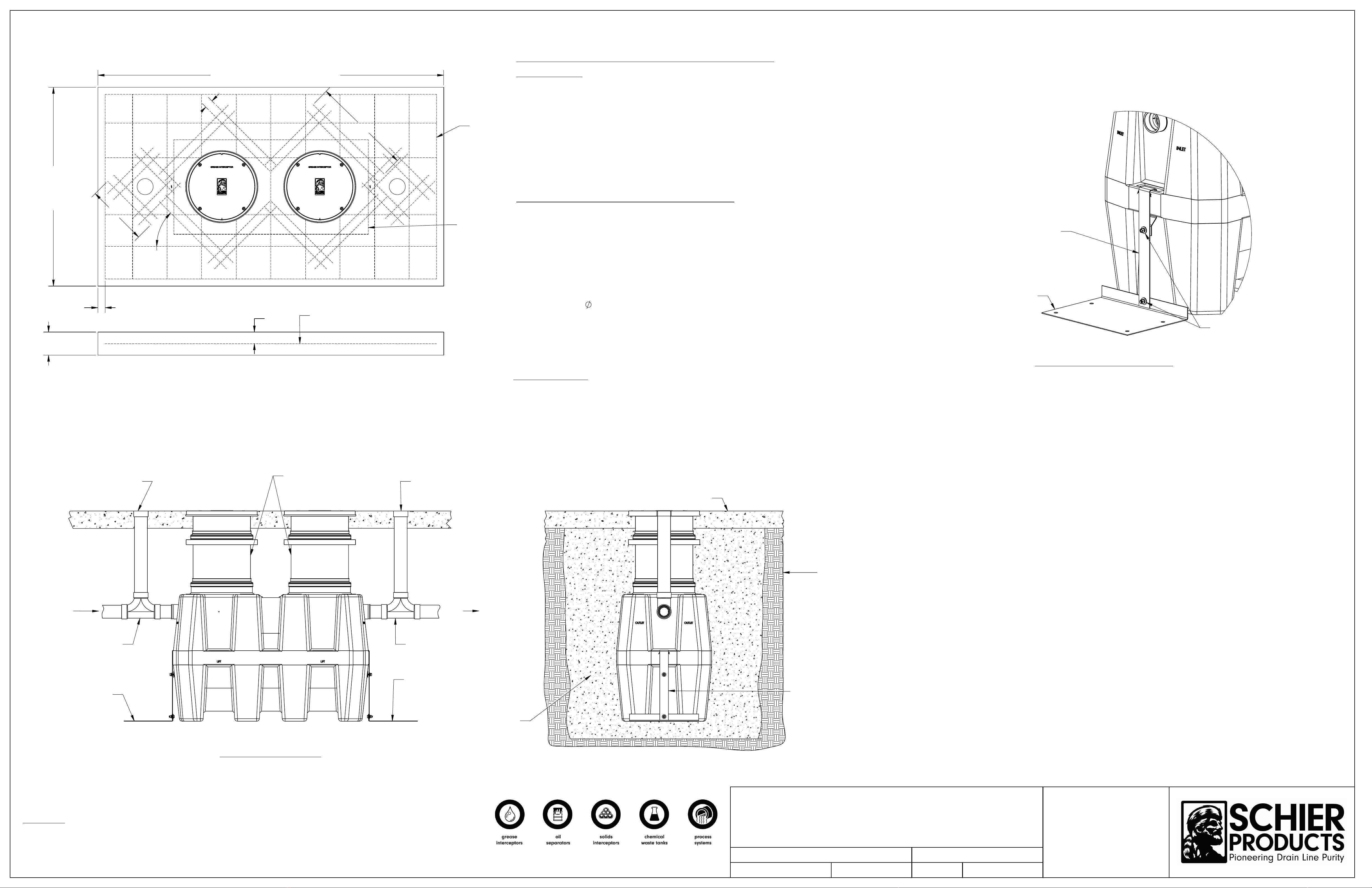
(;&$9$7,21$1'%$&.),//'(7$,/
,17(5,2525(;7(5,25
2-Way cleanout
tee (by others)
2-Way cleanout
tee (by others)
6,'(9,(:'(7$,/
Optional Anchor kit
see detail
Optional Anchor kit
see detail
Concrete slab
Native soil
Crushed aggregate
or sand
Optional Anchor kit
see detail
the unit footprint
Concrete Pad
must extend
18" outside
2 1/2"
Min.
18" outside the unit footprint
Concrete Pad must extend
8"
4"
Rebar
Finished Grade
Rebar
PS-275-B
Shown
&21&5(7(6/$%'(7$,/)2575$)),&/2$',1*
,17(5,2525(;7(5,25
36%6KRZQ
Top View
Elevation View
Stainless steel
anchor strap
Stainless steel
Anchor plate
Stainless hardware
$1&+25.,7,167$//$7,21'(7$,/
$QFKRU.LW,QVWDOODWLRQ6WHSV
Slide "Anchor Strap" over tie down point on end wall and
1.
bolt together using provided hardware.
Bolt "Anchor Strap" to "Anchor Plate" using provided hardware
2.
3. Hold down force achieved by backfill weight acting on Anchor Plate.
4. Anchor Plate may be bolted to concrete slab, if required, by using
holes provided in Anchor Plate.
)RUXQLWGHWDLOVVHHVSHFLILFDWLRQVKHHWIRUVHOHFWHGXQLW
&RQQHFWLQJSLSHDQGILWWLQJVE\RWKHUV
127(6
Schier solids interceptors are not to be installed in any other manner except as shown. Consult local
codes for separate trapping requirements, cleanout locations and additional installation instructions.
,17(5,2525(;7(5,25%(/2:*5$'(,167$//$7,21,16758&7,216
36%636%636%636%6
&211(&7,216
Connect waste piping to the unit.
1.
Handle of removable basket or screen bay be extended using 1-1/2" PCV pipe, if necessary.
2.
%(/2:*5$'(,167$//$7,21,16758&7,216
(;&$9$7,21
Install unit(s) as close as possible to fixtures being serviced.
1.
Width and length of excavation shall be minimum 12" greater
2.
than the tank on all sides.
Depth of excavation shall be 6" deeper than tank bottom.
3.
Set the tank in well-packed crushed aggregate material
4.
approximately 3/4" size rock, or sand, with no fines.
Anchor kit is recommended for installations in high water table conditions to
5.
prevent float out. To be determined by specifying engineer. If necessary,
order optional "Anchor Kit" (see detail right).
%$&.),//,1*),1,6+('&21&5(7(6/$%
Preparation of sub grade per geotech recommendations.
1.
Stabilize and compact sub grade to 95% proctor.
2.
Fill tank with water before backfilling to prevent float out during piping installation.
3.
Before backfilling and pouring of slab secure cover(s) and riser/s (if necessary) to the unit(s)
4.
Backfill using crushed aggregate material approximately 3/4" size rock, or sand,
5.
with no fines.
6. Place 6" aggregate base under slab. Aggregate should be 3/4" size rock, or sand, with no fines.
7. Thickness of concrete around cover to be determined by specifying engineer. If traffic
loading is required the concrete slab dimensions shown are for guideline
purposes only.
8. Concrete to be 28 day compressive strength to 4000 PSI.
9. NO. 4 rebar (
1/2") grade 60 steel per ASTM A615: connected with tie wire.
10. Rebar to be 2 1/2" from edge of concrete.
11. Rebar spacing 12" grid. 4" spacing around access openings.
12. All pipe penetrations to be sleeved or have slip connections.
'$7(
11/30/11
PS SERIES INSTALLATION, OPERATION
AND MAINTENANCE GUIDE
6FKLHU3URGXFWV
:RRGHQG5G
(GZDUGVYLOOH.6
7HO
)D[
ZZZVFKLHUSURGXFWVFRP
0DGHLQWKH86$
'(6&5,37,21
':*%<
EAS
5(9
01
'2&80(17180%(5
057-0650-01
THE INFORMATION CONTAINED IN THIS DRAWING IS THE SOLE PROPERTY OF
6&+,(5352'8&76
. ANY REPRODUCTION IN
PART OR AS A WHOLE WITHOUT THE WRITTEN PERMISSION OF
6&+,(5352'8&76
IS PROHIBITED.
35235,(7$5<$1'&21),'(17,$/
6+((7180%(5
3 of 6
(&2
1003
Riser (sold separately)
Rebar
PS-25-B Shown with Riser
2,500 lb.
Max. load
PS-25-B Shown
450 lb.
Max. load
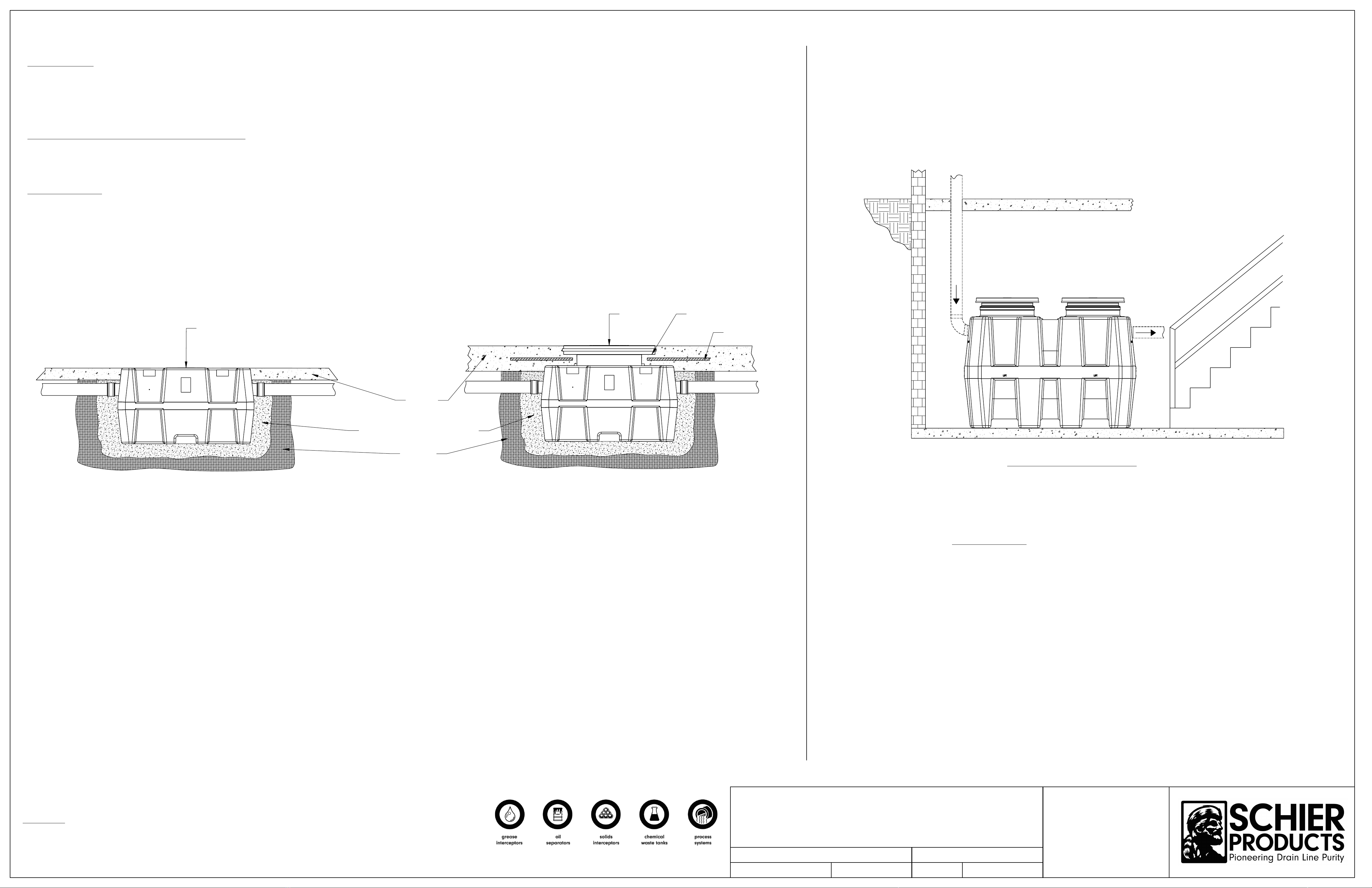
217+()/225'(7$,/
(PS-275-B SHOWN)
127(6
Schier solids interceptors are not to be installed in any other manner except as shown. Consult local
codes for separate trapping requirements, cleanout locations and additional installation instructions.
,17(5,25%(/2:*5$'(,167$//$7,21,16758&7,216
36%636%6
(;&$9$7,21
Install unit(s) as close as possible to fixtures being serviced.
1.
Width and length of excavation shall be minimum 6" greater
2.
than the tank on all sides.
Depth of excavation shall be 6" deeper than tank bottom.
3.
Set the tank in well-packed crushed aggregate #7 backfill material
4.
approximately 3/4" size rock, or sand, with no fines.
%$&.),//,1*),1,6+('&21&5(7(6/$%
Before backfilling and pouring of slab secure cover(s) to the unit(s).
1.
Backfill using crushed aggregate #7 backfill material approximately 3/4" size rock or sand
2.
with no fines.
3. Place 6" aggregate base under slab.
&211(&7,216
Connect waste piping to the unit.
1.
,17(5,25$%29(*5$'(,167$//$7,21,16758&7,216
366(5,(6
If concrete slab falls within body of unit, reinforce with rebar,
extending 6" beyond footprint of unit to connect main floor slab.
When the jobsite requires burying unit flush with floor without using
a riser kit, maximum cover/unit top load rating is 450 lbs.
Concrete
Crushed aggregate or sand backfill
Native soil
Install unit as close as possible to fixtures being serviced.
&211(&7,216
1. Connect waste piping to the unit.
'$7(
11/30/11
PS SERIES INSTALLATION, OPERATION
AND MAINTENANCE GUIDE
6FKLHU3URGXFWV
:RRGHQG5G
(GZDUGVYLOOH.6
7HO
)D[
ZZZVFKLHUSURGXFWVFRP
0DGHLQWKH86$
'(6&5,37,21
':*%<
EAS
5(9
01
'2&80(17180%(5
057-0650-01
THE INFORMATION CONTAINED IN THIS DRAWING IS THE SOLE PROPERTY OF
6&+,(5352'8&76
. ANY REPRODUCTION IN
PART OR AS A WHOLE WITHOUT THE WRITTEN PERMISSION OF
6&+,(5352'8&76
IS PROHIBITED.
35235,(7$5<$1'&21),'(17,$/
6+((7180%(5
4 of 6
(&2
1003

Adapter
Adapter
Cover
Cover
Gasket
Gasket
PS-275
(standard)
Upper clamp
Lower clamp
Lower clamp
Upper clamp
&XWORFDWLRQ&
LR24
(long riser)
(optional component)
Gasket
Upper Clamp
Lower Clamp
&XWORFDWLRQ%
SR24
(short riser)
(optional component)
Gasket
Lower Clamp
Upper Clamp
PS-35, PS-50,
PS-125
(standard)
Adapter
Cover
Gasket
Upper clamp
Lower clamp
Finished floor
Figure 1
Riser Height
Adapter
Unit
Call Schier with questions or suggestions @ 1-800-827-7119 Customer Service Hours: 7AM-5 PM CST
Figure 2
Adapter
Riser
Riser Height +
Distance from step 5
Cut
Mark
Figure 3
Adapter
Riser
H[FHHG
0XVWEHDWOHDVW
DQGFDQQRW
Gasket
Unit
Riser/Adapter
Upper Clamp
Lower Clamp
Figure 4
*3" for a GB-35 with 4" connections
5. Adjust
adapter
upwards to reach 20" to 22"
6. Adjust
adapter
upwards to reach 35" to 37"
&XWORFDWLRQ$
Adapter
Cover
Adapter & Cover
(standard component)
7RROVLQFOXGHGZLWKEDVHJUHDVHLQWHUFHSWRUXQLWV
7/16" Nut driver tool/bit
•
Silver permanent marker
•
7RROV1HHGHG
Tape measure
•
Regular or cordless drill with 1/2" chuck
•
7RROVQHHGHGLI5LVHUVUHTXLUHFXWWLQJ
Jigsaw or
•
Cordless circular saw or
•
Reciprocating saw
•
5LVHU$VVHPEO\,QVWUXFWLRQV6WHSV
If unit is to be installed on grade (on-the-floor), there is no need for any adjustments.
1.
Unit is ready to be put into service.
If unit is to be buried: Once unit is set so that the pipe connections line up with
2.
jobsite piping, measure total riser height needed from top of cover to finished
grade. Make sure you include any future tile work, etc. that may be installed
in your finished grade measurements. See figure 1.
Select according riser(s) needed based off Table 1.
3.
If riser(s) is needed, remove cover(s) from adapter and remove adapter from main
4.
unit by loosening upper clamp with included nut driver bit (lower band is factory
set do not adjust or remove). On the floor near the unit, insert adaptor into first riser
until it stops. If needed, insert bottom of first riser into top of second riser until it stops.
You may need to tighten upper clamps during this step to keep risers from shifting.
Adapter and riser(s) should sit level with each other. Removal of cover during this process
will ease assembly.
From the top of the adapter, measure your needed total riser height downward to the
5.
sidewall of the riser. Then, add
5”
(for PS-35 or PS-50) or
6”
( for PS-125, or PS-275).
For example, if you have a PS-275 and need a 15-1/2” extension, you would measure
down from the top of the adapter 21-1/2” (15-1/2” + 6” = 21-1/2”). See Figure 2.
Refer to Table 2, Table 3 or Table 3a to determine if, and where, any cuts need to be made.
6.
If a cut needs to be made, make a circular line around the sidewall of the riser with the
included silver marker at your riser height
+dimension from step 5
. Using a jigsaw, circular
saw or reciprocating saw, cut along your line. Discard/recycle the cutoff scrap.
Whether the riser needs to be cut or not, make another mark with the silver marker on the
7.
sidewall of the riser a distance of
4 INCHES
(3 INCHES for a OS-35 w/ 4” connections) above
the edge just cut. If you did not make a cut (meaning your riser height
+ dimension from
step 5
line was beyond the bottom edge of your riser), still mark the sidewall of the riser
4 INCHES above where your riser height
+ dimension from step 5
line would have been.
DO NOT cut this new line. Once the riser is installed into the main unit, this new line will end
up at the top of the gasket and will aid in re-assembly. See Figure 3.
IMPORTANT: Before the next step:
8.
Make sure both diffusers are installed inside the main unit at the appropriate locations
1.
and check if there needs to be any flow control adjustment on the inlet diffuser. Refer
to sheet 2 of the installation instructions for flow control adjustment.
Refer to sheet 1 of the installation instructions for leak/water testing procedures.
2.
Take riser(s) and adapters apart to reduce the weight during installation. Wipe all sidewalls and
9.
inside of gasket with a damp cloth to remove jobsite dust/debris. Install components into the main
unit starting from the lowest (cut) riser and working your way toward the finished floor level. Upper
clamps at each gasket need to be loosened or removed to aid in assembly. Once riser(s)/adapter
is inserted into gasket, upper clamp can be tightened.
Verify that the bottom of the lowest riser is protruding at least 2-1/2” but no more than 4” into
10.
the main unit from the top of the gasket. Your mark from step 7 should be at the top edge
of the gasket on the main unit. If measurements were made correctly, this should happen
automatically. See figure 4.
If tilting of the adapter is required to be flush with finished grade, it must be done AFTER all
11.
clamps have been tightened with riser(s)/adaptor in a vertical and level position. Tilting is
achieved by using the flexibility of the gasket. If tilting is done before clamps are tightened, a
perfect gasket seal may be compromised. Schier recommends tilting only the adapter versus the
entire riser assembly to make sure your riser height is maintained.
Tighten all clamps to a minimum of 5 and a maximum of 8 ft lbs. of torque. Use the same torque
12.
as you would tighten a rubber no-hub coupling.
The adapter must be adjusted
upward
to achieve certain extension heights. See Table 2,
13.
Table 3 or Table 3a.
If jobsite riser height conditions change after the above steps have been completed, there
14.
may still be room for vertical adjustment in both directions. As long as minimum and maximum
overlaps are maintained (see Figure 4), the adapter/riser(s) can be adjusted/cut as many times
as necessary. Please follow these steps from the beginning to ensure the proper overlaps are
maintained.
127(6
Schier solids interceptors are not to be installed in any other manner except as shown. Consult local
codes for separate trapping requirements, cleanout locations and additional installation instructions.
1. Adjust
adapter
upwards to reach 22" to 24"
2. Adjust
adapter
upwards to reach 37" to 39"
3. Adjust
adapter
upwards to reach 56" to 58"
4. Adjust
adapter
upwards to reach 70" to 72"
* For model PS-125-B with 6" connections, the adapter will
need to be trimmed if the riser height needed is between 0" - 2".
7. Adjust
adapter
upwards to reach 19" to 21"
8. Adjust
adapter
upwards to reach 34" to 36"
7HOH*OLGH5LVHU6HULHV,QVWDOODWLRQ*XLGHOLQHV
36363636
'$7(
11/30/11
PS SERIES INSTALLATION, OPERATION
AND MAINTENANCE GUIDE
6FKLHU3URGXFWV
:RRGHQG5G
(GZDUGVYLOOH.6
7HO
)D[
ZZZVFKLHUSURGXFWVFRP
0DGHLQWKH86$
'(6&5,37,21
':*%<
EAS
5(9
01
'2&80(17180%(5
057-0650-01
THE INFORMATION CONTAINED IN THIS DRAWING IS THE SOLE PROPERTY OF
6&+,(5352'8&76
. ANY REPRODUCTION IN
PART OR AS A WHOLE WITHOUT THE WRITTEN PERMISSION OF
6&+,(5352'8&76
IS PROHIBITED.
35235,(7$5<$1'&21),'(17,$/
6+((7180%(5
5 of 6
(&2
1003

36%6
Cover
(included with
base unit)
Riser Kit
36%6
)LJXUH
Finished floor
Fasten cover
Install riser
)LJXUH
Remove cover
Install ring / bolts
Finished floor
X"
)LJXUH
Finished floor
Install
Riser
X"
)LJXUH
Riser
Mark, cut,
and deburr
Riser
Bolts
Gasketed Ring
655LVHU.LW
6ROG6HSDUDWHO\
2-1/8" Min.
)LJXUH
16" Max.
7RROVLQFOXGHGZLWKULVHUNLW
Silver permanent marker
•
7RROV1HHGHG
Tape measure
•
Phillips head screwdriver
•
Jigsaw or
•
Cordless circular saw or
•
Reciprocating saw
•
5LVHU$VVHPEO\,QVWUXFWLRQV6WHSV
If unit is to be buried, you will need a riser kit (sold separately). The 16 Series TeleGlide Riser System for these models
1.
allows riser heights from 2-1/8" above standard unit up to 16". Only ONE riser may be used per base unit to allow sufficient
access to internal serviecable components. See Figure 5.
If more than 16" of riser height is needed, you will need to adjust jobsite requirements OR purchase the next available
2.
model with a 24 Series TeleGlide Riser System which allows taller riser heights.
Once unit is set so that pipe connections line up with jobsite piping, remove cover from unit. Fasten yellow gasketed ring to
3.
unit with hardware provided in separate riser kit. Ring flange with 4 bolt notches faces down against the unit. See Figure 1.
Push riser into ring until it stops (about 1 inch). See Figure 2.
4.
Measure the distance from the top edge of the riser down to the finished floor. Make sure to account for any future tile work
5.
in your measurment. See Figure 2.
Remove riser from ring. Take measurement from step 5 from the BOTTOM of the riser upwards towards the top of the
6.
riser. Mark a line around the riser, and cut with handsaw, jig saw, or reciprocating saw. Remove debris from cut edge with
scraper, utility knife, or gloves. See Figure 3.
Place cut riser back into ring on unit until it stops. Fasten cover from unit into riser with the same 4 bolts from the unit. Unit
7.
is ready to be water tested and backfilled. Install finished floor. See Figure 4.
127(6
Schier solids interceptors are not to be installed in any other manner except as shown. Consult local
codes for separate trapping requirements, cleanout locations and additional installation instructions.
7HOH*OLGH5LVHU6HULHV,QVWDOODWLRQ*XLGHOLQHV
36%636%6
Minimum and maximum riser heights when units are buried.
Measure
Measurement
from Figure 2
'$7(
11/30/11
PS SERIES INSTALLATION, OPERATION
AND MAINTENANCE GUIDE
6FKLHU3URGXFWV
:RRGHQG5G
(GZDUGVYLOOH.6
7HO
)D[
ZZZVFKLHUSURGXFWVFRP
0DGHLQWKH86$
'(6&5,37,21
':*%<
EAS
5(9
01
'2&80(17180%(5
057-0650-01
THE INFORMATION CONTAINED IN THIS DRAWING IS THE SOLE PROPERTY OF
6&+,(5352'8&76
. ANY REPRODUCTION IN
PART OR AS A WHOLE WITHOUT THE WRITTEN PERMISSION OF
6&+,(5352'8&76
IS PROHIBITED.
35235,(7$5<$1'&21),'(17,$/
6+((7180%(5
6 of 6
(&2
1003
This manual suits for next models
19
Table of contents
Popular Heating System manuals by other brands

Helios
Helios KWLC 350 manual

Healthy Climate
Healthy Climate HRV Series installation instructions and home owner's guide

S&P
S&P DOMEO 210 RD Disassembly instructions

Daikin
Daikin VRV IV REYQ-TAYCA Design manual

Innova
Innova HRC Series Installation, use and maintenance

Broan
Broan ERV140 ECM installation guide

Stuart Turner
Stuart Turner BEP 130 Installation, Operatation & Maintenance Instructions

Honeywell
Honeywell SDC Service manual

heatco
heatco HERO DIRECT Installation, operation and technical manual

Magic-Pak
Magic-Pak MGE4-09-18 Installation and maintenance instructions

Oxygen 8
Oxygen 8 NOVA Series Application, operation & maintenance

Delchi
Delchi Carrier 42N installation manual


