Schlage PIM400 User manual

*24303034*
24303034
PIM400-485 USER GUIDE
User guide for the panel interface module PIM400-485
Version 2
Version 1
(Manufacturing discontinued)
Para el idioma español, navegue hacia www.allegion.com/us
Pour la portion française, veuillez consulter le site www.allegion.com/us

2 • Schlage • PIM400-485 user guide
Contents
Overview...........................................................................................................................3
Getting started ..................................................................................................................3
Features............................................................................................................................4
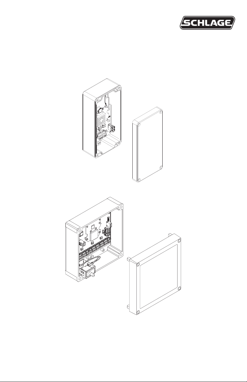
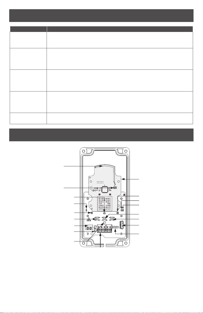
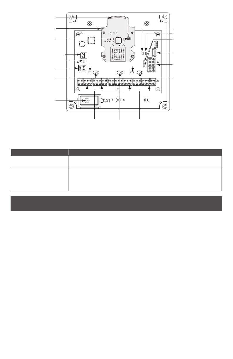
Components .....................................................................................................................4
Installation.........................................................................................................................5
Determine the location ..................................................................................................5
Pre-installation test........................................................................................................6
Drill holes for wiring.......................................................................................................6
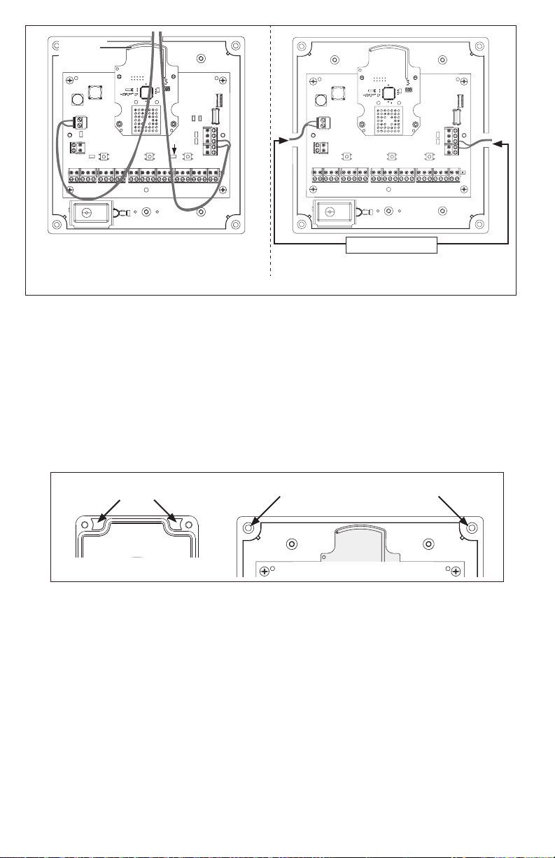
Mount the PIM400-485 .................................................................................................7
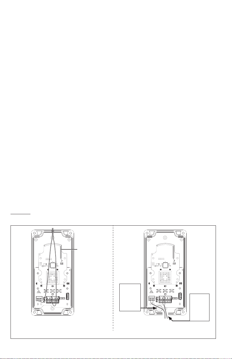
Wire routing...................................................................................................................8
Cable/wire specications ..............................................................................................8
Retrot...........................................................................................................................8
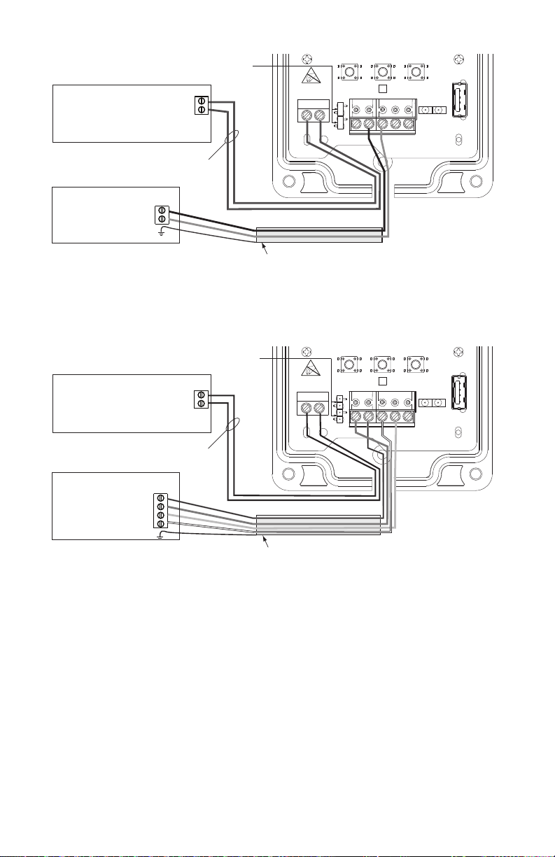
PIM400-485 to ACP connection........................................................................................9
Typical PIM400-485 to ACP wiring diagrams.............................................................. 10
Optional remote antenna ................................................................................................12
Link mode .......................................................................................................................12
Schlage Utility Software (SUS) .......................................................................................12
Reset to factory defaults .................................................................................................12
DC power........................................................................................................................13
Complete the installation ................................................................................................13
Troubleshooting ..............................................................................................................13
FCC/IC statements.........................................................................................................15
To comply with FCC and Industry Canada RF radiation exposure limits for general
population, the antenna(s) used for this transmitter must be installed such that a minimum
separation distance of 20 cm is maintained between the radiator (antenna) and all persons
at all times and must not be collocated or operating in conjunction with any other antenna or
transmitter.
This product is compliant of UL 294 and ULC S319 standard. This product’s compliance
would be invalidated through the use of any add-on, expansion, memory or other module
that has not yet been evaluated for compatibility for use with this UL Listed product, in
accordance with the requirements of the Standards UL 294 and ULC S319. This product has
been evaluated for ULC-S319 Class I.
UL294 Access Control Levels tested to: Destructive Attack - Level 1; Line Security - Level 1;
Endurance - Level 4; Standby Power - Level 1.

3 • Schlage • PIM400-485 user guide
Overview
This manual describes the installation, operation and interaction of all Schlage PIM400-485
models with Access Control Panels (ACPs) and Wireless Access Point Modules (WAPMs).
The PIM400-485 is a product in the AD-400 Wireless Panel Interface Module (WPIM)
category.
There are two versions of the PIM400-485. Both versions have the same features and
connections, and both have interchangeable congurations and settings.
• The PIM400-485 is wired to a UL or cUL Listed compatible Access Control Panel (ACP).
• The PIM400-485 has been evaluated for UL and cUL compliance in indoor applications
only, within the protected premises.
• Connect the PIM400-485 to external power using a UL294 Listed power limited power
supply for UL installations, and a ULC S318/ULC S319 Listed Power Supply for cUL
installations.
• Installation location is determined by the location of the WAPM. The PIM400-485 is
ideally installed very close to the ACP.
• The PIM400-485 communicates to the WAPM(s) using Radio Frequency (RF).
• The WAPM is installed at the access point where access will be controlled and/or
monitored.
• The PIM400-485 enclosure is NEMA Type 4.
Getting started
The following is an overview of the steps required to set up the PIM400-485:
1. Install the WAPM (AD-400, WPR400, etc). See the installation guide that came with the
WAPM or visit www.allegion.com/us for more information.
2. Make sure the PIM400-485 is located to allow for optimum RF signal transmission. See
Determine the location on page 5 for more information.
3. Before installing the PIM400-485, check for proper communication function and linking
with WAPM(s). See Pre-installation test on page 6 for more information.
4. Make sure to follow unique installation procedures if installing on an indoor metallic
wall. Refer to Mount the PIM400-485 on page 7 for more information. Consult the
Schlage Utility Software User Manual for information about conguring the PIM400-485
and the WAPM.
5. Familiarize yourself with the information contained in this user guide.
This user guide is for the PIM400-485 only.
Save this user guide for future reference.

4 • Schlage • PIM400-485 user guide
Features
Feature Description
Power status Power status is indicated by the Power/Tamper LED. When the
PIM400-485 is powered and tamper is not detected (cover is on), the
Power/Tamper LED will illuminate steady green.
ACP
communication
status
ACP communication status is indicated by the receive (RX) LED and
the transmit (TX) LED. When the PIM400-485 communicates with an
ACP, the receive (RX) LED and the transmit (TX) LED will continuously
ash randomly.
WAPM
communication
status
WAPM Communication Status is indicated by the link 1 LED and the
link 2 LED. When the PIM400-485 communicates with a WAPM, the
link 1 LED will blink if the WAPM is assigned an odd number, and the
link 2 LED will blink if the WAPM is assigned an even number.
Tamper status Tamper Status is indicated by the power/tamper LED. When the cover
is o, tamper is detected and the power/tamper LED will ash green.
When the cover is on, tamper is not detected and the power/tamper
LED will illuminate steady green.
Reset Reset is performed by the reset button. Press the reset button if the
PIM400-485 does not seem to work properly.
Components
Aux/Tamper
Connector (P6)
Not used
Reset Button (SW3)
Link 2 Button (S3)
USB Connector (J1)
RS485
Connector (P4)
Receive LED (LED2)
12-24 VDC 2I4
WIRE RDA–TDA–RDB+ TDB+GND AUXTAMPER
RX ITX
ATTENTION
ELECTROSTATIC
SENSITIVE DEVICE
POWER
TAMPER
PIM400-485
RS485
+ POWER -
USB
MOUNT THIS SIDE UP
Internal Antenna
External Antenna
Connector
2|4 Wire Jumpers (P5)
Power Connector (J2)
Link 1 Button (SW1)
Link 1 LED (LED4)
Power/Tamper LED (LED1)
Optical Transmitter (LED6) Link 2 LED (LED5)
Optical Receiver (U6)
Transmit LED (LED3)
Antenna Module
PIM400-485 (Version 2)

5 • Schlage • PIM400-485 user guide
Not used
(J8, J7)
Not used
(J10, J11)
Reset
Button
(S1)
Power/Tamper LED (D3)
Link 2 Button (S3)
Link 1 Button (S2)
Tamper Switch
Connector (J1)
2
|
4 Wire Jumpers
(J19, J20)
Power Connector (J2)
Link 1
LED
USB Connector (J9)
RS485 Connector (J5)
Tamper Switch
Internal Antenna
Receive LED (D4)
Transmit LED (D5)
External Antenna
Connector
Link 2 LED
Antenna Module
PIM400-485 (Version 1)
Component Description
RS485 connector The PIM400-485 connects up to 16 WAPMs to an Access Control
Panel using the RS485 connection.
Power connector The PIM400-485 power input is non-polarized. If power is lost
or cycled, upon restoring power, the PIM400-485 will continue
operation with the same conguration and linking information.
There is no need to re-congure or re-link.
Installation
Determine the location
The PIM400-485 communicates with WAPMs using radio frequency (RF) signals. RF signals
are diminished by walls, distance, metal objects or barriers. Consider the following when
placing the PIM400-485:
• Mount the PIM400-485 within 200 horizontal feet (61 meters) of each WAPM with typical
building construction. When clear line-of-sight is available, communication may be
possible up to 1000 feet (305 meters).
• Do not mount the WAPM(s) and the PIM400-485 on dierent oors. The signal may be
degraded and functionality could be severely limited.
• Do not mount the PIM400-485 on a metal surface. A separation of at least one inch
must be maintained in all directions from any metal.
• Signal will not pass through metal walls or metal mesh in the walls (stucco). Use a
remote antenna module located outside the room when necessary.
• Moving vehicles will interrupt the signal. Placement distance should be reduced by half
when vehicles may temporarily block the signal.
• Mount the PIM400-485 or the remote antenna so that the antenna is vertical for
optimal communication.
Locations and wiring methods shall be in accordance with the National Electrical Code,
ANSI/NFPA 70 for U.S. and Canadian Electrical Code for Canada.

6 • Schlage • PIM400-485 user guide
Pre-installation test
Once the location for a PIM400-485 is estimated to support the WAPM(s), check
performance prior to installation.
If using a remote antenna module, install the antenna as indicated in the ANT400 user guide.
1. As close as possible to its exact mounting location, temporarily mount the WAPM to the
access control point (i.e. door, gate, elevator). Do not connect power yet.
The WPR400 may be used as a portable range tester to facilitate properly locating the
PIM400-485.
2. Temporarily mount the PIM400-485 in the exact location and orientation it will be mounted.
3. Power the PIM400-485 with a 12 or 24 VDC supply capable of delivering 250 mA.
4. Put the PIM400-485 into link mode. Refer to Link mode on page 12.
5. Go to the most distant WAPM being tested and apply power.
6. Put the WAPM into link mode. Refer to the WAPM’s User Guide for Link instructions.
7. Verify that linking has occurred, indicated at the WAPM by the green LED ashing and
optionally by an internal sounder beeping. The number of green ashes and audible beeps
will be the same as the channel number to which the PIM400-485 is set.
If linking occurred successfully on the rst WAPM, repeat the pre-installation test on any
additional WAPMs. If all linking is successful, follow steps to wire and mount the PIM400-485
and any additional WAPMs (see Drill holes for wiring on page 6).
• If linking is unsuccessful, move the PIM400-485 six to ten inches (15.2 to 25.4 cm) in
any convenient direction until all WAPMs link successfully. If still not successful, move
the PIM400-485 closer to the WAPMs and repeat the pre-installation test, or add more
PIM400-485s.
• If still not successful, RF interference may be the cause. Refer to the Schlage Utility
Software user guide for information on changing the RF channel.
Drill holes for wiring
Drill hole(s) in the PIM400-485 enclosure to accommodate the size and number of entry/exit
connectors to be used.
Drill a hole in the top of the PIM400-485 for remote antenna installation only.
DO NOT run signal or power wiring through the top of the PIM400-485 enclosure.
Be sure to follow all local electrical code requirements.
12-24 VDC 2I4
WIRE RDA–TDA–RDB+ TDB+GND AUXTAMPER
RX ITX
ATTENTION
ELECTROSTATIC
SENSITIVEDEVICE
POWER
TAMPER
PIM400-485
RS485
USB
MOUNT THIS SIDE UP
Internal
antenna
12-24 VDC 2I4
WIRE RDA–TDA–RDB+ TDB+GND AUXTAMPER
RX ITX
ATTENTION
ELECTROSTATIC
SENSITIVEDEVICE
POWER
TAMPER
PIM400-485
RS485
USB
MOUNT THIS SIDE UP
Z\x”
(25 mm)
hole
(primary
location)
Z\x”
(25 mm)
hole
(alternate
location)
IMPROPER Wire Routing PROPER Wire Routing
PIM400-485 (Version 2)

7 • Schlage • PIM400-485 user guide
Internal
antenna
Z\x” (13 mm) holes
IMPROPER Wire Routing PROPER Wire Routing
PIM400-485 (Version 1)
LA single drill hole may be used for wire routing, however be sure to avoid
routing wires near the internal antenna and the mechanical tamper switch.
LIf using a remote antenna module, an additional hole is required. Refer to the
ANT400 user guide for drilling instructions.
Mount the PIM400-485
1. Remove the cover and place the PIM400-485 against the wall in the location where it
successfully passed the pre-installation test.
2. Mark the four (4) mounting hole locations on the wall with a pencil using the PIM400-485
enclosure as a template.
LBe sure to mount the PIM400-485 vertically (refer to diagrams on page 6).
PIM400-485 (version 2) PIM400-485 (version 1)
Mounting holes Mounting holes
3. Remove the PIM400-485 from the wall and drill the four holes (Z\zn” diameter drill bit
recommended).
LIf the wall does not adequately support the PIM400-485, wall anchors should
be used.
4. Place the PIM400-485 against the wall where the four holes are drilled and screw four
screws into the mounting holes (#6 screws recommended).
LIf mounted on a metallic surface or where metal is within 1 inch (25 mm) of the
back of the PIM400-485, mount the PIM400-485 at least 1 inch (25 mm) from
the wall.
LIf a remote antenna is to be used, refer to the ANT400 user guide.

8 • Schlage • PIM400-485 user guide
Wire routing
Avoid routing the wires near the internal antenna and the tamper detection mechanism.
Improper wire routing may reduce RF performance and/or prevent tamper detection. Wire
routing inside the enclosure should be as short as possible. Do not coil any excess wire inside
the enclosure.
Refer to wire routing diagrams on page 6 and page 7.
Cable/wire specications
Application Part number AWG Description Max distance
DC Power
Input Belden 8760 or equivalent 18 2 Conductor 1000 Feet
(305 meters)
RS485
Belden 9841 or 9842 or equivalent, or
as specied by local electrical codes
or the ACP provider
24 2 or 4 Conductor
shielded
4000 Feet
(1219 meters)
Retrot
If desired, to retrot an existing PIM400-485 (version 1) installation with a PIM400-485
(version 2), complete the following steps:
1. Disconnect all electrical connections to the PIM400-485 (version 1) PCBA.
2. Remove the four screws from the PIM400-485 (version 1) PCBA. Set aside two (2) of
the screws for later use.
3. Remove the PIM400-485 (version 1) PCBA from the enclosure.
4. Drill a Z\x” (25 mm) wire routing hole in the bottom of the PIM400-485 (version 2) as
shown below.
5. Place the PIM400-485 (version 2) into the PIM400-485 (version 1) enclosure as shown
below.
6. Secure the PIM400-485 (version 2) enclosure to the PIM400 (version 1) enclosure using
the two screws removed at step 2.
Enclosure covers for both the PIM400-485 (version 2) and PIM400-485 (version 1) are used
when installing the retrot conguration.
If a remote antenna is to be
used, refer to the ANT400
user guide.
The retrot installation
procedure is not evaluated
by UL/cUL.
12-24 VDC 2
I
4
WIRE RDA–TDA–RDB+ TDB+GND AUXTAMPER
RX
I
TX
ATTENTION
ELECTROSTATIC
SENSITIVE DEVICE
POWER
TAMPER
PIM400-485
RS485
+ POWER -
USB
MOUNT THIS SIDE UP
PIM400-485
(version 1)
Enclosure PIM400-485
(version 2)
Secure with
two screws

9 • Schlage • PIM400-485 user guide
PIM400-485 to ACP connection
Review Components on page 4 and page 5 before connecting the PIM400-485 to
an Access Control Panel.
CAUTION: Disconnect the Access Control Panel power and batteries before wiring the
PIM400-485 to the panel.
WARNING: Because every Access Control Panel is dierent, always check the panel’s
instruction manual for appropriate interface wiring.
The EIA RS485 specication labels the data wires as “A” and “B”, however, many RS485
products label their wires “+” and “-”. Some products associate the “+” signal with “A”,
some with “B”. Reversing polarity will not damage either RS485 device, it will just not
communicate; if it does not work, switch the connections.
• The wires from the Access Control Panel must be a shielded twisted pair. For maximum
wire lengths and cable specications, refer to Cable/wire specications on page 8.
• For compliance with UL 294 or ULC S319, product must be used with a UL 294 or
ULC S319 Listed Access Control Panel or unit, respectively.
• Must be used with a UL294 or ULC S318/ULC S319 Listed power-limited Power Supply
capable of sourcing at least 250 mA @ 12 or 24 VDC.
ACCESS CONTROL PANEL CONNECTIONS
PIM400-485
connector
PIM400-485
signal
Access control
panel signal Description
Power (J2)
+12 or 24 VDC
PIM400-485 inputs for 12 or 24 VDC power.
Draws 250mA max.
If the Access Control Panel (ACP) reader
power outputs do not source enough
current for the PIM400-485, use the ACP
main regulated 12 VDC power supply or
a separate UL294 or ULCS318/ULCS319
Listed 12 or 24 VDC power-limited power
supply.
Power input is non polarized.
– DC Ground
RS485 (P5)
RDA – – Receive Data 4-Wire or 2-Wire bi-directional RS485
communication port for interface to Access
Control Panels.
2-Wire installation: Both 2|4 wire jumpers
should be added.
4 -Wire installation: Both 2|4 wire jumpers
should be removed.
Refer to Typical PIM400-485 to ACP wiring
diagrams on page 10 and page 11.
TDA – – Transmit Data
RDB + + Receive Data
TDB + + Transmit Data
GND Signal Ground

10 • Schlage • PIM400-485 user guide
Typical PIM400-485 to ACP wiring diagrams
12-24 VDC 2|4
WIRE RDA–TDA–RDB+ TDB+GND AUXTAMPER
RX ITX
ATTENTION
ELECTROSTATIC
SENSITIVE DEVICE
POWER
TAMPER
PIM400-485
RS485
USB
MOUNT THIS SIDE UP
+
−
RDA-
TDA-
RDB+
TDB+
A-
B+
+
−
12-24 VDC 2|4
WIRE RDA–TDA–RDB+ TDB+GND AUXTAMPER
ATTENTION
ELECTROSTATIC
SENSITIVE DEVICE
POWER
TAMPER
PIM400-485
RS485
P5
P5
USB
Install Jumpers
Power Supply
UL294 or ULCS318/
ULCS319 Listed power limited
250mA 12 or 24 V DC
2-Wire
4-Wire
Access Control
Panel
Shield
Access Control
Panel
Shield
Power Supply
UL294 or ULCS318/
ULCS319 Listed power limited
250mA 12 or 24 V DC
Remove Jumpers
18 AWG, 1000 feet
max. run length
18 AWG, 1000 feet
max. run length
PIM400-485 Version 2

11 • Schlage • PIM400-485 user guide
J5
J2
GND
TDB+
RDB+
TDA-
RDA-
J20
J19
A-
B+
+
−
J20
J19
J5
J2
GND
TDB+
RDB+
TDA-
RDA-
RDA-
TDA-
RDB+
TDB+
+
−
Power
Supply
UL294 or
ULCS318/
ULCS319
Listed power
limited 250mA
12 or 24 V DC
2-Wire
4-Wire
Access
Control
Panel
Shield
Shield
18 AWG,
1000 feet max.
run length
18 AWG,
1000 feet max.
run length
Remove Jumpers
Install Jumpers
Access
Control
Panel
Power
Supply
UL294 or
ULCS318/
ULCS319
Listed power
limited 250mA
12 or 24 V DC
PIM400-485 Version 1

12 • Schlage • PIM400-485 user guide
Optional remote antenna
The PIM400-485 may be used with a remote antenna when:
• the PIM400-485 needs to be located in a remote, more serviceable or secure area,
• the RF range needs to be increased, or
• the PIM400-485 needs to communicate with a WAPM located outdoors.
LWhen the optional remote antenna is used, the PIM400-485 internal antenna will
be disabled.
Optional remote antenna models are shown below. For more information on remote antenna
use and installation, refer to the ANT400 optional remote antenna user guide.
The optional remote antenna is not evaluated by UL.
OPTIONAL REMOTE ANTENNA MODELS
Model Enclosure Location Description
ANT400-REM-CEILING Indoor Optional remote omni-directional
antenna (0 dB gain)
ANT400-REM-I/O NEMA 4 Indoor/
Outdoor
Optional remote omni-directional
antenna (0 dB gain)
ANT400-REM-HALL Indoor Optional remote bi-directional
antenna (3.5 dB gain)
ANT400-REM-I/O+6dB NEMA 4 Indoor/
Outdoor
Optional remote directional antenna
(6 dB gain)
Link mode
The PIM400-485 can be placed into link mode using the Schlage utility software (SUS) on the
handheld device (HHD). Refer to the Schlage utility software user guide for information.
The PIM400-485 can also be placed into Link Mode directly through select Access Control Panels.
Schlage Utility Software (SUS)
The Schlage utility software is used for programming and setup only.
The SUS is used to congure this device’s links and outputs. For information about the SUS,
refer to the Schlage utility software user guide.
Reset to factory defaults
All conguration information will be deleted and the PIM400-485 will be reset to factory defaults!
1. Remove the PIM400-485 cover.
2. Press and hold the Link 1 button and Link 2 button for about three (3) seconds.
The Link 1 LED and the Link 2 LED will ash red when factory default reset
conguration begins.
3. Release both the Link 1 button and Link 2 button. The Link 1 LED and the Link 2
LED will ash green when factory default reset conguration is complete.
4. Replace the PIM400-485 cover.

13 • Schlage • PIM400-485 user guide
DC power
This connection is always required regardless of the system application or conguration.
Refer to page 9 for instructions to connect DC power to the PIM400-485.
Complete the installation
After all required connections have been made, connect the power and Access Control
Panel standby batteries (optional) to the panel. Standby batteries are required for ULCS319
applications for Access Control Panels and must be able to provide 30 minutes of standby
for Class I. The system must be tested for operation at least once per year. Refer to Access
Control Panel installation instructions for additional details.
Troubleshooting
Problem Possible cause Solution
The PIM400-485 does
not communicate with
the Access Control
Panel.
The RS485 cable between
the PIM400-485 and the
Access Control Panel may
be damaged.
Replace the RS485 cable between
the PIM400-485 and the Access
Control Panel.
The RS485 signals between
the PIM400-485 and the
Access Control Panel may
be wired incorrectly.
Refer to PIM400-485 to ACP
connection on page 9 or ACP
system documentation for proper
wiring instructions.
The RS485 address of
the PIM400-485 may not
match the RS485 address
assigned in the Access
Control Panel.
Change the RS485 address of the
PIM400-485 to match the RS485
address assigned within the Access
Control Panel. Refer to the Schlage
utility software guide for more
information.
The 2 | 4 wire jumpers (P5)
may be improperly installed
for communication with
RS485 4-Wire or improperly
removed for communication
with RS485 2-Wire.
Install the 2 | 4 wire jumpers (P5)
when communicating with RS485
2-Wire. Remove the 2 | 4 wire
jumpers when communicating with
RS485 4-Wire. Refer to Typical
PIM400-485 to ACP wiring diagrams
on page 10 and page 11.

14 • Schlage • PIM400-485 user guide
Problem Possible cause Solution
The PIM400-485
reports false tamper
detections to the
Access Control Panel.
An intense light source
may cause interference
with the optical receiver
(version 2 model only)
when the enclosure cover is
removed.
Move the PIM400-485 (version 2
model only) away from the intense
light source and ensure that the
enclosure cover is installed.
Improper wiring may cause
interference with the optical
transmitter and optical
receiver (version 2 model
only).
Improper wiring may cause
false tamper detection at
the ACP (version 1 model).
Refer to Wire routing on page 8
for proper wire routing instructions.
The PIM400-485 does
not communicate with
Wireless Access Point
Modules (WAPMs)
The Antenna Module may
not be properly installed.
Ensure that the Antenna Module is
installed and properly seated.
Wiring may cause
interference with the
internal antenna on the
Antenna Module.
Check to ensure that wiring is
properly routed in the PIM400-485
enclosure and the area around
the internal antenna is clear of any
wire. See Wire routing on page
8 for more information.
The PIM400-485 may not
be linked to the Wireless
Access Point Module
(WAPM).
Link the PIM400-485 to the
Wireless Access Point Module.
See Link mode on page 12 for
more information. Also refer to the
Wireless Access Point Module’s
User Guide for Link instructions.

15 • Schlage • PIM400-485 user guide
FCC/IC statements
The communication module is a 900 MHz transceiver for electronic locks and non-lock devices. The communication
module links the access device to the Access Control Management System, with feedback control to the Access
Device via a wireless means. The module contains the embedded rmware implementing the radio physical and
data layers. There are 5 antennas approved for use with this module:
Approved antenna list:
The required antenna impedance is 50 ohms.
1. PCB trace antenna with a 5.7dBi maximum gain
2. p/n: 23520587, dual beam antenna with a 3.5dBi gain (ANT400-REM-HALL)
3. p/n: 23530579, multi band directional panel antenna with 8.5dBi gain (ANT400-REM-I/O+dB)
4. p/n: 23530553, dual band quasi-omni panel antenna with 4.5dBi gain (ANT400-REM-I/O)
5. p/n: 23520561, multi band omni antenna with 2dBi gain (ANT400-REM-CEILING)
Antennas having a gain greater than the antenna type approved in the list are strictly prohibited for use with this
device. However, antennas of the same type with a gain equal to or less may be used. Examples of this may
include:
• a directional panel antenna with a gain equal to or less than 8.5 dBi may be used with this module
• an omni-directional antenna with a gain equal to or less than 2.0 dBi may be used with this module
Specications of the radio module:
Power output: 18.6 dBm Modulation: BPSK-40 Operating frequency: 906 -924 MHz
Note: The intended use of this module is not for the general public. It is generally for industry/commercial use only.
This transceiver is to be professionally installed in the end product by Allegion, and not by a third party. The Schlage
XPB-COMAD400V2 900 MHz Communication Board Module will not be sold to third parties via retail, general public
or mail order. In the case of a repair, the transceiver will be replaced by a professional Installer.
Federal Communication Commission interference statement
This equipment has been tested and found to comply with the limits for a Class B digital device, pursuant to Part 15
of the FCC Rules. These limits are designed to provide reasonable protection against harmful interference in a
residential installation. This equipment generates uses and can radiate radio frequency energy and, if not installed
and used in accordance with the instructions, may cause harmful interference to radio communication. However,
there is no guarantee that interference will not occur in a particular installation. If this equipment does cause harmful
interference to radio or television reception, which can be determined by turning the equipment o and on, the user
is encouraged to try to correct the interference by one of the following measures:
• Reorient or relocate the receiving antenna.
• Increase the separation between the equipment and receiver.
• Connect the equipment into an outlet on a circuit dierent from that to which the receiver is connected.
• Consult the dealer or an experienced radio/TV technician for help.
This device complies with Part 15 of the FCC Rules.
Operation is subject to the following two conditions: (1) This device may not cause harmful interference, and
(2) this device must accept any interference received, including interference that may cause undesired operation.
FCC/IC caution
Any changes or modications not expressly approved by the party responsible for compliance could void the user’s
authority to operate this equipment.
To comply with FCC/IC RF exposure limits for general population/uncontrolled exposure, the antenna(s) used for
this transmitter must be installed to provide a separation distance of at least 20 cm from all persons and must not be
collocated or operating in conjunction with any other antenna or transmitter.
Industry Canada statements
This Device complies with Industry Canada License-exempt RSS standard(s). Operation is subject to the following
two conditions:
(1) this device may not cause interference, and
(2) this device must accept any interference, including interference that may cause undesired operation of the
device.
Under Industry Canada regulations, this radio transmitter may only operate using an antenna of a type and
maximum (or lesser) gain approved for the transmitter by Industry Canada. To reduce potential radio interference
to other users, the antenna type and its gain should be so chosen that the equivalent isotropically radiated power
(e.i.r.p.) is not more than that permitted for successful communication.
This radio transmitter, 8053B-COMAD400V2, has been approved by Industry Canada to operate with the
antenna types listed below with the maximum permissible gain and required antenna impedance for each
antenna type indicated.

© 2014 Allegion
Printed in U.S.A.
24303034 Rev. 04/18-c
Customer Service
1-877-671-7011 www.allegion.com/us
Approved antenna list:
The required antenna impedance is 50 ohms.
1. PCB trace antenna with a 5.7dBi maximum gain
2. p/n: 23520587, Dual Beam Antenna with a 3.5dBi gain (ANT400-REM-HALL)
3. p/n: 23530579, Multi band Directional Panel antenna with 8.5dBi gain (ANT400-REM-I/O+dB)
4. p/n: 23530553, Dual Band Quasi-Omni Panel Antenna with 4.5dBi gain (ANT400-REM-I/O)
5. p/n: 23520561, Multi band Omni Antenna with 2dBi gain (ANT400-REM-CEILING)
Antennas having a gain greater than the antenna type approved in the list are strictly prohibited for use with this
device. However, antennas of the same type with a gain equal to or less may be used. Examples of this may
include:
• a directional panel antenna with a gain equal to or less than 8.5 dBi may be used with this module
• an omni-directional antenna with a gain equal to or less than 2.0 dBi may be used with this module.
To comply with IC RF exposure limits for general population/uncontrolled exposure, the antenna(s) used for this
transmitter must be installed to provide a separation distance of at least 20 cm from all persons and must not be
collocated or operating in conjunction with any other antenna or transmitter.
This manual suits for next models
1
Table of contents
Other Schlage Control Unit manuals
Popular Control Unit manuals by other brands

National Instruments
National Instruments NI 9250 Getting started guide

Vertiv
Vertiv Liebert SmartAisle2 user manual

Thermasol
Thermasol WHSP10S installation manual

Frequency Central
Frequency Central Dual XVCA Build documentation

Sony
Sony HXCU-TX70 Service manual

Valve Concepts
Valve Concepts 3000 SERIES Installation, operation and maintenance manual