Schlage PIM400-1501 User manual

*23855075*
23855075
PIM400-1501 User Guide
Installation and operating instructions for Schlage PIM400-1501
Para el idioma español, navegue hacia www.allegion.com/us
Pour la portion française, veuillez consulter le site www.allegion.com/us

2 • Schlage • PIM400-1501 user guide
Contents
Overview...........................................................................................................................3
Getting started ..................................................................................................................5
Schlage Utility Software (SUS) .........................................................................................5
Link mode .........................................................................................................................5
Put the PIM400-1501 into link mode.............................................................................5
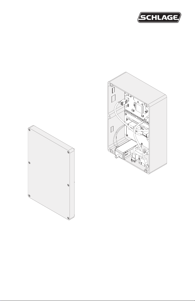
Install the PIM400-1501....................................................................................................6
Determine the location ..................................................................................................6
Pre-installation test........................................................................................................6
Installation.....................................................................................................................7
Permanently mount the PIM400-1501 .......................................................................... 7
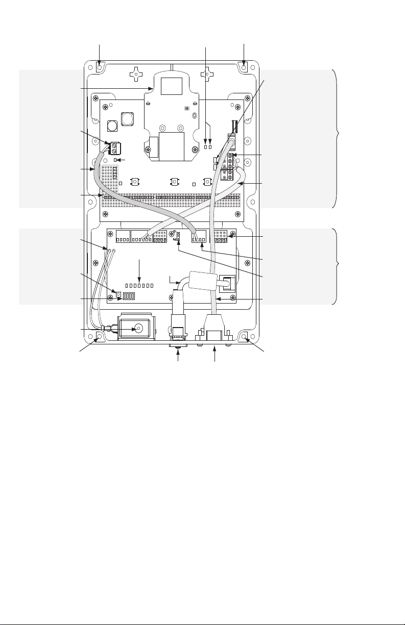
Wiring connections ...........................................................................................................8
12 VDC input power......................................................................................................8
PoE Input Power ...........................................................................................................8
Cable recommendations ...............................................................................................8
Network connection ..........................................................................................................9
Ethernet connection ......................................................................................................9
DIP switches .................................................................................................................9
Remote antenna (if applicable)....................................................................................... 10
Antenna location and safety........................................................................................10
Antenna grounding......................................................................................................10
Terminate the coax whip at the PIM400-1501............................................................. 11
Reset to factory defaults .................................................................................................12
Reset the PIM400-485 to factory defaults...................................................................12
Reset the EP-1501 to factory defaults - bulk erase.....................................................12
Memory backup battery ..................................................................................................12
PIM400-1501 LED reference ..........................................................................................13
FCC/IC statements.........................................................................................................14
To comply with FCC and Industry Canada RF radiation exposure limits for general
population, the antenna(s) used for this transmitter must be installed such that a minimum
separation distance of 20 cm is maintained between the radiator (antenna) and all persons
at all times and must not be co-located or operating in conjunction with any other antenna or
transmitter.
This product is a UL-294 & ULC-S319 Listed Class 1 equipment. This product’s UL & ULC
compliance would be invalidated through the use of any add-on, expansion, memory or
other module that has not yet been evaluated for compatibility for use with this product, in
accordance with the requirements of the Standards set forth in UL-294 & ULC-S319.
UL294 Access Control Levels tested to: Destructive Attack - Level 1; Line Security - Level 1;
Endurance - Level 4; Standby Power - Level 1.

3 • Schlage • PIM400-1501 user guide
Overview
The Schlage PIM400-1501 combines the Schlage PIM400-485 and EP-1501 Access
Platform into a single product.
The Schlage PIM400-1501-LC provides the Schlage PIM400-485 in an enclosure designed
to receive an EP-1501 board.
LPlease refer to the PIM400-1501-LC instructions for further information on
completing the installation of the EP-1501 board (see instruction sheet number
P516-781). Once the EP-1501 board is installed, the PIM400-1501-LC operates as
the PIM400-1501 as described in this guide.
LFor UL installations, the PIM400-1501-LC must be used with an EP-1501 board
that is UL294 listed.
The PIM400-1501 communicates over Ethernet to host software, and by wireless
transmission with up to 16 AD-Series Wireless Access Point Modules (WAPMs). WAPMs
compatible with the PIM400-1501 include the Schlage AD-400 locks, WRI400 and WPR400.
This manual describes the operation and installation of the Schlage PIM400-1501.
• The PIM400-1501 is wired to an Ethernet network connection.
• The PIM400-1501 is powered externally one of two ways, selected by the power
selector jumper, J3:
a. Power over Ethernet (PoE), Class 3, fully compliant to IEEE 802.3af, or
b. 12 VDC power supply connected to TB4-3 (VIN) and TB4-4 (GND). The 12 VDC
power supply must be compatible with all components and must have the
capacity to power the PIM400-1501 and any other devices attached to the same
supply. (The PIM400-1501 requires a power supply capable of sourcing at least
400 mA @ 12 VDC).
For UL installations, PoE powered devices shall not be used.
Power for these devices must be provided by a UL-294 listed, ULC-S318 Listed or
ULC-S319 Listed power limited power supply capable of sourcing at least 400 mA at
12 VDC.
Use of the Model CENB1010A1265C02 with the PIM400-1501 is permitted for
UL-294 Listed applications only.
• Ideal installation location is determined by the location of the WAPM(s).
• The PIM400-1501 communicates to the WAPM(s) using Radio Frequency (RF).
• The WAPM is installed at the access point where access will be controlled and/or
monitored.
• The PIM400-1501 is suitable for indoor use, ambient temperature range 0°C to +66°C
(+32°F to +151°F).
• SRAM is protected against power outage by a rechargeable battery.
• Please refer to the Access Control Panel manufacturer’s instructions and documentation
for information on operation of the ACP.
• Please refer to Mercury documentation for the latest updates and information on the
Mercury product.

4 • Schlage • PIM400-1501 user guide
PIM400-485
EP1501
TB1 TB2 TB4
J1, J7, J8, J10, J11
NOT USED
J19/J20,
Shorting Blocks
shorted=2 wire RS485
MUST BE INSTALLED
J2
12VDC Power
Connector J5
RS-485
Connector
RS-485 Wiring
Tamper Switch
Radio Module
Mounting
Hole
Mounting
Hole
Mounting
Hole
Status LEDs
S2, Reset
Switch
S1, Dip Switches
DC Power Wiring
J3, PoE/12VDC
Selector Jumper
Mounting
Hole
USB
Connector
Ethernet
Connector
Ethernet
Cable
TB3, TB5
NOT USED
VIN, GND 12VDC
Input Power
RX/TX
LEDs
Link 1
Power
LED
Link 2Reset
IN1,Tamper
Switch Connection
USB Cable
TB3 TB5
PIM400-1501 Printed Circuit Board Assembly

5 • Schlage • PIM400-1501 user guide
Getting started
The following is an overview of the steps required to set up the PIM400-1501.
1. Install the WAPM (AD-400, WRI400, etc). See the installation guide that came with the
WAPM(s) or visit www.allegion.com/us for more information.
2. Make sure the PIM400-1501 is located to allow for optimum RF signal transmission.
See Determine the location on page 6 for more information.
3. Before installing the PIM400-1501, check for proper communication function and linking
with WAPM(s). See Pre-installation test on page 6 for more information.
4. The PIM400-1501 requires an Ethernet network connection in order to connect with host
software.
5. The PIM400-1501 has been evaluated for UL compliance in indoor applications only.
6. Make sure to follow unique installation procedures if installing on an indoor metallic wall.
Refer to Permanently mount the PIM400-1501 on page 7 for more information.
7. Consult the Schlage Utility Software (SUS) user guide for information about conguring
the PIM400-1501 and the WAPM(s).
8. Familiarize yourself with the information contained in this user guide.
Save this user guide for future reference.
Schlage Utility Software (SUS)
• The SUS is used for programming and setup only.
• The SUS is used to congure and link WAPMs to the PIM400-1501.
LThe PIM400-1501 will report as a PIM400-485-RSI on the SUS.
LWhen upgrading the PIM400-485 rmware, make sure to upgrade with PIM400-
485-RSI rmware.
LWhen the SUS is connected to the PIM400-1501, RS485 communication between
the PIM400-485 and EP-1501 is interrupted. The PIM400-1501 is not controlling
door access at this time.
For information about using the SUS, see the Schlage Utility Software user guide.
Link mode
Put the PIM400-1501 into link mode
To initiate linking, place the PIM400-1501 in link mode first, then place the desired
WAPM in link mode.
1. Place the PIM400-1501 into link mode. Refer to the SUS user guide for detailed Link
instructions.
2. Place the desired WAPM into link mode. Refer to instructions in the “Linking” section of
the user guide for the WAPM.
LNote: When utilizing the SUS application to initiate link mode, the PIM400-1501 must
rst be coupled to the SUS. To couple with the device, the lid must be removed from the
PIM400-1501.

6 • Schlage • PIM400-1501 user guide
Install the PIM400-1501
Determine the location
The PIM400-1501 communicates with WAPM(s) using radio frequency (RF) signals and with
host software using an Ethernet network connection. RF signals are diminished by walls,
distance, metal objects or barriers. Consider the following when placing the PIM400-1501:
• Mount the PIM400-1501 in a location where a live Ethernet network connection will be
available.
• Mount the PIM400-1501 within 200 horizontal feet of each WAPM. When clear line-of-
sight is available, communication may be possible up to 1000 feet.
• Do not mount the WAPM(s) and the PIM400-1501 on dierent oors. The signal may be
degraded and functionality could be severely limited.
• Do not mount the PIM400-1501 directly onto a metal surface. A separation of at least
one inch must be maintained in all directions from any metal.
• Signals will not pass through metal walls or metal mesh in the walls (stucco). Use a
remote antenna module (ANT400) located outside the room when necessary.
• Moving vehicles will interrupt signals. Placement distance should be reduced by half
when vehicles may temporarily block the signal.
• Mount the PIM400-1501 (or the remote antenna, if used) so that the antenna is
vertical for optimal communication.
Pre-installation test
Once locations for the PIM400-1501 and WAPM(s) are determined, check performance
prior to installation.
LIf using a remote antenna module, install the antenna as indicated in the optional
remote antenna module (ANT400) user guide.
1. As close as possible to its exact mounting location, temporarily mount the WAPM to the
access control point (i.e. door, gate, elevator).
LA WPR400 may be used as a portable range tester to facilitate properly locating the
PIM400-1501.
2. Temporarily mount the PIM400-1501 in the exact location and orientation it will be
mounted.
3. Power the PIM400-1501 with a 12 VDC supply capable of delivering 400 mA or PoE,
Class 3, 12.95W, fully compliant to IEEE 802.3af.
LFor UL installations, PoE powered devices shall not be used. Power for these
devices must be provided by a UL294 listed power limited power supply capable
of sourcing at least 400 mA at 12 VDC (example: Schlage models PS902, PS904,
PS906).
4. Put the PIM400-1501 into link mode. The PIM400-1501 will stay in link mode for 30
minutes or until linking to a WAPM has taken place. Refer to Link mode on page 5.
5. Go to the WAPM being tested and put the WAPM into link mode. Refer to instructions in
the “Linking” section of the user guide for the WAPM.
6. Verify that linking has occurred, indicated at the WAPM by the green LED ashing and
optionally by an internal sounder beeping. The number of green ashes and audible
beeps should be the same as the RF channel number to which the PIM400-1501 is set.

7 • Schlage • PIM400-1501 user guide
Installation
1. If linking was successful, install the PIM400-1501. Install and link additional WAPMs.
2. If linking was unsuccessful, move the PIM400-1501 six to ten inches in any convenient
direction and repeat steps 4 through 6 of the Pre-Installation Test (see page 6) until all
WAPMs link successfully. If linking is still unsuccessful, move the PIM400-1501 closer to
the WAPM(s) and repeat, or add more PIM400-1501 modules.
LIf still not linking successfully, RF interference may be the cause. Refer to the SUS
user guide for information on changing the RF channel, and/or consider using a
remote antenna module (ANT400).
Permanently mount the PIM400-1501
Follow these steps to permanently mount the PIM400-1501 to its desired location.
1. Place the PIM400-1501, cover removed, against the wall in the position where it successfully
linked.
2. Orient the PIM400-1501 vertically with the radio board at the top of the enclosure.
3. Drill four holes, >\cx” diameter drill bit, 1C\v” deep, located to match the mounting holes as
shown on page 3.
4. If the location does not adequately support the PIM400-1501, wall anchors should be
used (not included).
5. If mounted on a non-metallic surface or where no metal is within 1 inch (25 mm) of the
back of the PIM400-1501, attach the PIM400-1501 directly to the wall using appropriate
#8 mounting hardware.
6. If mounted on a metallic surface or where metal is within 1 inch (25 mm) of the back of
the PIM400-1501, attach the PIM400-1501 1 inch (25 mm) from the wall.
LIf a remote antenna is to be used, refer to the optional remote antenna module
(ANT400) user guide.

8 • Schlage • PIM400-1501 user guide
Wiring connections
LIMPORTANT: When drilling holes in the PIM400-1501 to accommodate the 12 VDC
power cable, ensure that the drill bit does not damage any electronics inside the
enclosure. Use light drill pressure to prevent the bit from entering the enclosure
very far, or use a stop drill bit no longer than Z\x” (13 mm) to prevent the bit from
damaging electronics inside the enclosure.
LWhen using the internal antenna, attention to wire routing is very important.
Improper wire routing will reduce the RF range. Wires inside the enclosure should
be as short as possible (i.e. do not coil any excess wire inside the enclosure).
12 VDC input power
• If powering the PIM400-1501 with 12 VDC, drill a hole in the enclosure to accommodate
the 12 VDC cable. DO NOT drill this hole in the top of the enclosure. Holes in the top
of the PIM400-1501 are for remote antenna installation only. DO NOT run power wiring
through the top of the PIM400-1501 enclosure. Keep all wiring away from the radio
module.
• Use cable entry/exit connectors that comply with local electrical codes (i.e. conduit, etc.).
• 12 VDC power is required for UL294 installations. The 12 VDC power supply must be
compatible with all components and must have the capacity to power the PIM400-1501
and any other devices attached to the same supply. (The PIM400-1501 requires a power
supply capable of sourcing at least 400 mA @ 12 VDC).
• Connect the 12 VDC cable to TB4-3 (VIN), TB4-4 (GND).
• Set the PoE/12 VDC power selector jumper (J3) to “12V”.
PoE Input Power
• If powering the PIM400-1501 with PoE, there is no need for a hole to be drilled in
the PIM400-1501 enclosure to accommodate power. Power is delivered through the
Ethernet cable.
• Set the PoE/12 VDC power selector jumper (J3) to “PoE”.
Cable recommendations
Application AWG Description Max Distance
12 VDC Power Input 18 2 Conductor 1000 Feet
Ethernet Connection - CAT5 or higher 300 Feet

9 • Schlage • PIM400-1501 user guide
Network connection
Ethernet connection
Connect a live Ethernet connection to the Ethernet port on the PIM400-1501. The green LED
on the PCBA Ethernet port will light up when a live network connection is present.
The PIM400-1501 is shipped with the factory default network settings shown below.
DIP switches
The four switches on S1 DIP switches congure the operating mode of the EP-1501 processor.
DIP switches are read on power-up except where noted. Pressing switch S2 causes the
EP-1501 to reset.
Switch
4
Switch
3
Switch
2
Switch
1Denition
O xO O Normal operating mode
x x x On
After initialization, enable default User Name (admin)
and Password (password). The switch is read on the
y, no need to reboot.
O x On O
Factory default network connection parameters
Network: Static IP address, 192.168.0.251
Subnet Mask: 255.255.0.0
Default Gateway: 192.168.0.1
DNS Server: 192.168.0.1
Host port: IP Server, no encryption, port 3001
Communication Address: 0
O x On On
Schlage OEM Default Communication Parameters
With the Schlage OEM code, the network connection
parameters are set by DHCP. The DHCP hostname
is “MAC” followed by the 12 digit MAC address of the
device (e.g., MACxxxxxxxxxxxx).
If a dierent OEM code besides Schlage is
loaded into the PIM400-1501, the OEM default
communication parameters may be dierent than
DHCP.
x On x x Disable TLS secure link. Switch is only read when
logging on the web page.
All other switch settings are unassigned and reserved for future use.
LNote: In order to ensure that the default login account is not enabled indenitely,
the EP controllers have been changed as follows:
• Even if no user accounts have been created, the default login account is not
automatically enabled.
• Enabling the default user account: switch DIP SW1 from OFF to ON and log in within 5
minutes.
• Rebooting the board or logging in within 5 minutes will disable the default account until
DIP SW1 is transitioned again.
• “Password” is not a valid password for a user account as it matches the default login.

10 • Schlage • PIM400-1501 user guide
Remote antenna (if applicable)
LIf the installation requires a remote antenna, refer to the optional remote antenna
module (ANT400) user guide for complete instructions and information on the
following antenna models.
Antenna Model Application
ANT400-REM-CEILING Intended for indoor applications.
ANT400-REM-HALL
ANT400-REM-I/O Intended for indoor or outdoor applications.
ANT400-REM-I/O+6dB
Antenna location and safety
• Locate within 15 cable feet (4.5 meters) of the PIM400-1501.
• Locate for best RF line-of-sight path between the PIM400-1501 and WAPM(s).
• Ensure the antenna and WAPM(s) are located on the same oor of a building.
• Outside antenna systems should not be located near overhead power lines or other
electric circuits, or where the antenna can fall into such power lines or circuits. Extreme
care should be taken to keep the antenna from touching any power line or circuit.
WARNING: Antenna contact with electric power lines or close proximity to a high
voltage electrical eld may cause serious or fatal injury.
Antenna grounding
National Electrical Code (NEC) requires that every antenna installation be properly
grounded. Local electrical codes may have additional requirements.
• A grounding block is recommended for all antenna installations. Consult the NEC and
local electrical codes, and the local Authority Having Jurisdiction (AHJ) for information
on proper grounding of the antenna system.
• A grounding block kit compatible with all of the previously mentioned antenna models is
available as a kit (sold separately, part number MGB + MCA5). Be sure to consider the
length of the grounding block cable when locating the antenna.
For more information, refer to Accessories in the optional remote antenna module
(ANT400) user guide.

11 • Schlage • PIM400-1501 user guide
Terminate the coax whip at the PIM400-1501
LOnly applicable to installations using an optional remote antenna.
1. Drill a B\,” (16 mm) hole in the top of the PIM400-1501 enclosure as shown to
accommodate the mounting of the coax whip to be connected to the PIM400-1501 radio
board.
Reverse MCX plug
Top of PIM400-1501
Enclosure
1¹⁄₂”
(38 mm)
⁵⁄₈” (16 mm) hole
1¹⁄₄”
(32 mm)
To avoid damage to electronics inside the enclosure when drilling, use light pressure so that
the bit does not penetrate very far, or use a stop drill bit no longer than ½” (13 mm) to stop
the bit from damaging electronics inside the enclosure.
2. Refer to the optional remote antenna module (ANT400) user guide for complete coax
connection instructions.

12 • Schlage • PIM400-1501 user guide
Reset to factory defaults
Reset the PIM400-485 to factory defaults
All conguration information will be deleted and the PIM400-485 will be reset to factory
defaults!
1. Remove the main cover.
2. Press and hold both link buttons for over 3 seconds.
3. Release both link buttons. The PIM400-485 will blink the red lights beside each link
button while conguration reset takes place.
4. The two green lights beside the link buttons will blink 3 times when the reset is
complete.
5. Replace the main cover.
Reset the EP-1501 to factory defaults - bulk erase
Use the bulk erase procedure on the EP-1501 to erase all conguration and cardholder
databases.
1. Set S1 switches to 1 and 2 ON, and 3 and 4 OFF.
2. Cycle power to the PIM400-1501, or press the S2 reset button on the EP-1501.
3. The EP-1501 is now in a 10 second reset window. LEDs 1, 2 and 3, 4 will blink
alternately.
4. Within the 10 second window, change switch 1 or 2 to the OFF position. This will erase
the EP-1501 memory. While erasing memory, LED 2 will blink at a 2 second rate. DO
NOT CYCLE POWER. Memory will be erased in less than 60 seconds.
5. LEDs 1 and 4 will blink for 10 seconds after the memory has been erased, then the
EP-1501 will re-boot.
6. Set the DIP switches to the desired network connection settings and cycle power, or
press the S2 reset button on the EP-1501. Refer to DIP switches on page 9 for more
information on network connection settings.
Memory backup battery
The EP-1501 SRAM is backed up by a rechargeable battery when input power is removed.
This battery allows for retention of data for approximately two (2) weeks.
If data in the SRAM is determined to be corrupt after power up, all data, including ash
memory, is considered invalid and is erased. If this should occur, all conguration data must
be downloaded again.
LThe initial charge of the backup battery may take up to 24 hours to fully charge.

13 • Schlage • PIM400-1501 user guide
PIM400-1501 LED reference
LED Condition PIM400-485 PCBA
Link 1 / Link 2
(L
ED1 / LED2
)
Solid GREEN Power applied
Alternating RED/GREEN ashing Link mode
More GREEN ashing than RED Strong wireless link
More RED ashing than GREEN
Weak wireless link
LED1: RED ashing
Communicating with odd # WAPM
LED2: RED ashing
Communicating with even # WAPM
RX/TX
(D4/D5)
RX and TX ashing RS485 communication with EP1501
USB communication with HHD
RX and TX alternating ash Coupling mode
LED1
RED Flashing Host communication activity
RED Flashing RS485 communication with PIM400-485
Solid RED Lid tamper active
Normal operating mode
DIP Switch Settings
Note: Locations of objects and scale of diagram are approximate.
Contact your local authorized dealer or visit www.schlage.com/support
80% RED ON Online
20% RED ON Oine
Power/Tamper
(D3)
LED Condition EP1501 PCBA
LED2
LED3
LED6
YEL
GRN
OFF
ON
OFF
ON or Flashing
10 Mb/S Ethernet speed
100 Mb/S Ethernet speed
No network activity
Network activity
1
2
3
4
OFF
ON
OFF
OFF X
After initialization, enable default User Name (admin) and
Password (password). The switch is read on the y; no need to reboot.
Factory Default Communication Parameters
OEM default communication parameters.
Contact system manufacturer for details.
Disable TLS secure link. Switch is read only when logging on the web page.
X
X
X
X
X
X
X
XON
ONON
ON OFF
OFF
OFF
Denitions Press and hold both LINK1 and LINK2 buttons for
three seconds and release.
RESET - COUPLING - BULK ERASE
Factory Default Reset
Coupling Press and hold LINK1 button, then press LINK2
button three times.
With power OFF, set DIP switches 1& 2to ON and
3& 4to OFF. Apply power and change switch 1or
2to OFF within 10 seconds.
Bulk Erase Conguration
Memory
12V
PoE
LINK 1 LINK 2
RESET
RX TX
PWR/
Tamper
LEDs
1
2
3456
7
DIP
12
34
YEL
GRN
12V/PoE Power
Selector Jumper
RESET

14 • Schlage • PIM400-1501 user guide
FCC/IC statements
The communication module is a 900 MHz transceiver for electronic locks and non-lock devices. The communication
module links the access device to the Access Control Management System, with feedback control to the Access
Device via a wireless means. The module contains the embedded rmware implementing the radio physical and
data layers. There are 5 antennas approved for use with this module:
Approved antenna list:
The required antenna impedance is 50 ohms.
1. PCB trace antenna with a 5.7dBi maximum gain
2. p/n: 23520587, dual beam antenna with a 3.5dBi gain (ANT400-REM-HALL)
3. p/n: 23530579, multi band directional panel antenna with 8.5dBi gain (ANT400-REM-I/O+dB)
4. p/n: 23530553, dual band quasi-omni panel antenna with 4.5dBi gain (ANT400-REM-I/O)
5. p/n: 23520561, multi band omni antenna with 2dBi gain (ANT400-REM-CEILING)
Antennas having a gain greater than the antenna type approved in the list are strictly prohibited for use with this
device. However, antennas of the same type with a gain equal to or less may be used. Examples of this may
include:
• a directional panel antenna with a gain equal to or less than 8.5 dBi may be used with this module
• an omni-directional antenna with a gain equal to or less than 2.0 dBi may be used with this module
Specications of the radio module:
Power output: 18.6 dBm Modulation: BPSK-40 Operating frequency: 906 -924 MHz
Note: The intended use of this module is not for the general public. It is generally for industry/commercial use only.
This transceiver is to be professionally installed in the end product by Allegion, and not by a third party. The Schlage
XPB-COMAD400V2 900 MHz Communication Board Module will not be sold to third parties via retail, general public
or mail order. In the case of a repair, the transceiver will be replaced by a professional Installer.
Federal Communication Commission interference statement
This equipment has been tested and found to comply with the limits for a Class B digital device, pursuant to Part
15 of the FCC Rules. These limits are designed to provide reasonable protection against harmful interference in a
residential installation. This equipment generates uses and can radiate radio frequency energy and, if not installed
and used in accordance with the instructions, may cause harmful interference to radio communication. However,
there is no guarantee that interference will not occur in a particular installation. If this equipment does cause harmful
interference to radio or television reception, which can be determined by turning the equipment o and on, the user
is encouraged to try to correct the interference by one of the following measures:
• Reorient or relocate the receiving antenna.
• Increase the separation between the equipment and receiver.
• Connect the equipment into an outlet on a circuit dierent from that to which the receiver is connected.
• Consult the dealer or an experienced radio/TV technician for help.
This device complies with Part 15 of the FCC Rules.
Operation is subject to the following two conditions: (1) This device may not cause harmful interference, and
(2) this device must accept any interference received, including interference that may cause undesired operation.
FCC/IC caution
Any changes or modications not expressly approved by the party responsible for compliance could void the user’s
authority to operate this equipment.
To comply with FCC/IC RF exposure limits for general population/uncontrolled exposure, the antenna(s) used for
this transmitter must be installed to provide a separation distance of at least 20 cm from all persons and must not be
co-located or operating in conjunction with any other antenna or transmitter.
Industry Canada statements
This Device complies with Industry Canada License-exempt RSS standard(s). Operation is subject to the following
two conditions:
(1) this device may not cause interference, and
(2) this device must accept any interference, including interference that may cause undesired operation of the
device.
Under Industry Canada regulations, this radio transmitter may only operate using an antenna of a type and
maximum (or lesser) gain approved for the transmitter by Industry Canada. To reduce potential radio interference
to other users, the antenna type and its gain should be so chosen that the equivalent isotropically radiated power
(e.i.r.p.) is not more than that permitted for successful communication.
This radio transmitter, 8053B-COMAD400V2, has been approved by Industry Canada to operate with the antenna
types listed below with the maximum permissible gain and required antenna impedance for each antenna type
indicated.

15 • Schlage • PIM400-1501 user guide
Approved antenna list:
The required antenna impedance is 50 ohms.
1. PCB trace antenna with a 5.7dBi maximum gain
2. p/n: 23520587, Dual Beam Antenna with a 3.5dBi gain (ANT400-REM-HALL)
3. p/n: 23530579, Multi band Directional Panel antenna with 8.5dBi gain (ANT400-REM-I/O+dB)
4. p/n: 23530553, Dual Band Quasi-Omni Panel Antenna with 4.5dBi gain (ANT400-REM-I/O)
5. p/n: 23520561, Multi band Omni Antenna with 2dBi gain (ANT400-REM-CEILING)
Antennas having a gain greater than the antenna type approved in the list are strictly prohibited for use with this
device. However, antennas of the same type with a gain equal to or less may be used. Examples of this may
include:
• a directional panel antenna with a gain equal to or less than 8.5 dBi may be used with this module
• an omni-directional antenna with a gain equal to or less than 2.0 dBi may be used with this module.
To comply with IC RF exposure limits for general population/uncontrolled exposure, the antenna(s) used for this
transmitter must be installed to provide a separation distance of at least 20 cm from all persons and must not be
collocated or operating in conjunction with any other antenna or transmitter.

Customer Service
1-877-671-7011 www.allegion.com/us
© Allegion 2018
Printed in U.S.A.
23855075 Rev. 04/18-e
This manual suits for next models
2
Table of contents
Other Schlage Control Unit manuals
Popular Control Unit manuals by other brands

Larson Electronics
Larson Electronics LM-SYM-XX-CTRL-R1 instruction manual

Diankong Electronics
Diankong Electronics DK-BT-MUSIC-21A quick guide

Becker
Becker Beck-O-Tronic 5 Assembly and operating instructions

Roughneck
Roughneck 27893 owner's manual

Mitel
Mitel M685i quick start guide

IMST
IMST iC880A quick start guide