8
Testing
Test Outputs
Regardless of the CTE mode, the Test buttons for the LOCK, ALARM
and AUX outputs can always be used. Even when commissioned and
LINKED, CTE Test buttons will change the state of the outputs when
held in.
LOCK
Test Button
When pushed the LOCK output
relay, LOCK power output, and
the CTE amber LOCK LED will
change state.
Check the lock/
unlock of the wired
strike, trim or QEL.
ALARM
Test Button
When pushed the ALARM
output relay, ALARM power
output, and the CTE amber
AUX LED will change state.
Alarm will sound
when wired
correctly.
AUX
Test Button
When pushed the AUX output
relay, AUX power output, and
the CTE amber AUX LED will
change state.
If wired correctly
will signal the Auto
Operator.
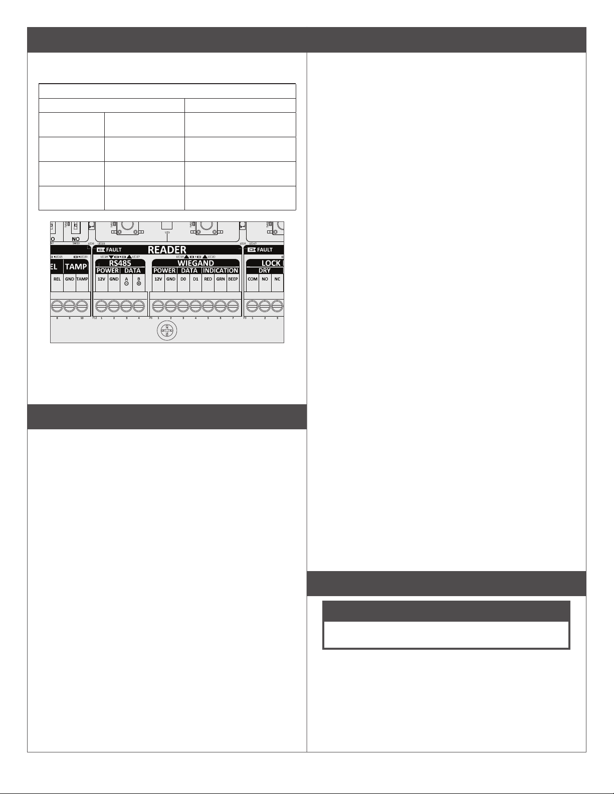
Test RS-485 Credential Reader
Use this button push sequence to test the reader connection in any
CTE MODE.
1. Test and sync the CTE with the RS-485 reader.
2. Push and release the CTE SCHLAGE button, followed by two
quick pushes on the FDR button.
3. A correctly wired MTB11, MTB15, MT11-485 or MT15-485 will
beep and blink amber three times.
Test Input LEDs
In any mode the inputs to the CTE can tested by checking the input
LEDs.
REN Short the REN & GND input, the
amber REN LED will light. The
SETTINGS switch above the
inputs will reverse this logic.
When REN is wired to
an external switch to
signal request to enter.
REX Short the REX & GND input, the
amber REX LED will light. The
SETTINGS switch above the
inputs will reverse this logic.
When REX is wired to
the inside lever or push
pad switch, an inside
lever turn or push pad
active will be indicated
with the REX LED.
DPS Short the DPS & GND input, the
amber DPS LED will light. The
SETTINGS switch above the
inputs will reverse this logic.
When wired to a door
DPS, an open door will
be indicated with the
amber DPS LED.
Test CTE Wi-Fi connection when enabled and used after
commissioning
commissioning when connected with the ENGAGE mobile app.
1. Use the ENGAGE mobile app to get audits from CTE.
2.
Audit Result Meaning
Validation Failed
automatically renew.
Associated with
network AP
Connection to the wireless router was
successful.
Connected to host Internet connection to the server was
successful.
Test LINKED status
Tests the CTE LINKED status only after the CTE is commissioned and
LINKED.
1. Connect to the Gateway with the ENGAGE mobile app.
2.
the CTE is LINKED. The app will show all devices linked to the
Gateway and their signal strengths.
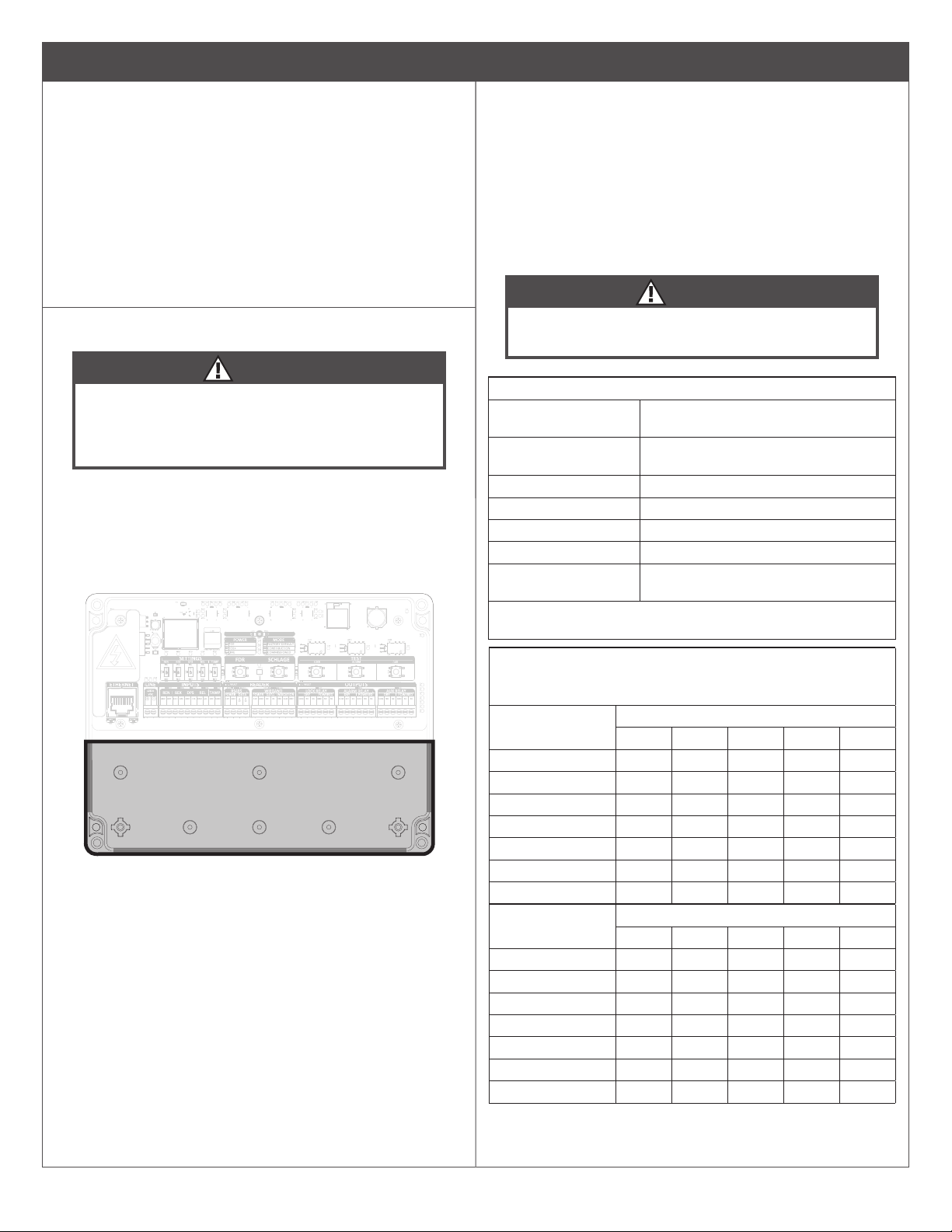
Status LED Indications
Location of Status LED
Status LED Indications Table
Solid Red LOCK Relay in secure state
Solid Green LOCK Relay in passage state
3x Green Flash on power up Power On Self Test (POST) passed
3x Red Flash on power up Power On Self Test (POST) failed
1x Long Green Flash Factory default reset successful
2x Red Flash Factory default reset failed
5x Green Flash Master construction credential
programmed
Steady Blue Flash Bluetooth active
Steady Amber Flash Wi-Fi active
Alternating Red/Green Flash Firmware update in progress
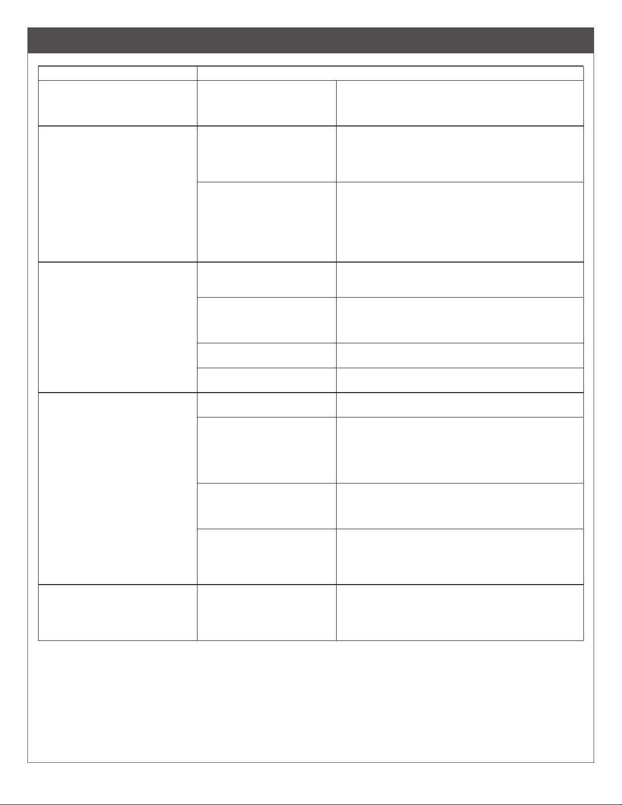
Quick Reference Guide
Bluetooth
advertising
Press and release SCHLAGE button when
FDR status LED is illuminated. This will allow
a 2 minute time for the ENGAGE Mobile app
to connect.
Factory Default
Reset
Press and hold FDR button for 5 seconds,
then press SCHLAGE button 3 times.
FACTORY DEFAULT mode LED will illuminate.
Enter Construction
Mode
Press and hold SCHLAGE button for
5 seconds. FACTORY DEFAULT and
CONSTRUCTION mode LEDs will both
illuminate. Present credential to the reader
within 20 seconds to create the Master
Construction Credential. Once created, the
and the CONSTRUCTION Mode LED will
remain illuminated.
Test Outputs Press the LOCK, ALARM, or AUX buttons to
test the LOCK, ALARM, or AUX outputs. Each
button will activate both the Dry and Powered
contacts.
IP LINKING Use the IP Gateway to LINK with a
commissioned CTE. After commissioning no
action is need at the CTE to link.
Temporary
de-linking from
Gateway
Press and hold the Schlage button for 5
seconds to temporarily de-link from Gateway.