Schmalz SB-L-EX User manual

30.30.01.00158 Status 07.2017
Index 01
Bedienungsanleitung
Schmalz Blower SB-L-EX
J. Schmalz GmbH
Johannes-Schmalz-Str. 1
D - 72293 Glaen
Tel +49 +7443 / 2403 - 0
Fax +49 +7443 / 2403 - 259
hp://www.schmalz.com
e-mail: [email protected]
Seite / Page 1/6
1 Bedienungsanleitung Schmalz Blower SB-L-EX
Zuordnung
Diese Betriebsanleitung gilt für den folgenden Seiten-
kanalverdichter:
Schmalz Blower SB-L-EX
mit den folgenden technischen Daten:
* Werte in Klammern nur kurzfristig im zyklischen Betrieb
zu erreichen, siehe Einsatzbedingungen
Baujahr: 2017
Max. Oberächentemperatur:
125°C (50Hz)
200°C (60Hz)
Umgebungstemperatur:
-15°C < t < 40°C
Ex-Kennzeichnung:
50Hz→ExII3G/3GDcIIB125°C(T4)
60Hz→ExII3G/3GDcIIB200°C(T3)
Sicherheitsbestimmungen
BittebeachtenSiedieSicherheitsnormDIN
EN1012-2fürVakuumpumpen.
Umbauten oder Veränderungen am
Seitenkanalverdichter können nur mit
ZustimmungdesWerkeserfolgen.
Durch die Luftverdichtung entstehen hohe
Temperaturenbis125°C.DenVerdichter
so aufstellen, dass heiße Oberächen
nicht berührt werden können oder den
VerkehrsbereichschützenoderWarnhinweiseanbringen.
Bestimmungsgemäße Verwendung
Dieser Seitenkanalverdichter ist für den Betrieb in Be-
reichen zugelassen, in denen nach Kategorie 3:
NurseltenundwährendeineskurzemZeitraumseine
explosionsfähigeAtmosphärevorhandenist.
DerBloweristmiteinemMotorentsprechendderRichtline
2014/34/EUausgestattet.
Der Seitenkanalverdichter wird zur Erzeugung von Un-
terdruck(Vakuum)eingesetzt.
Die Kenndaten des Typenschildes gelten bis zu einer
Höhevon800müberNN.
Er ist zumAnsaugen von nichtexplosionsfähigen Ge-
mischengeeignet.ImInnerndarfkeineexplosionsfähige
Atmosphäreauftreten.EristungeeignetzurFörderung
oderVerdichtungtoxischeroderbrennbarerMedien.
Den Seitenkanalverdichter so betreiben, dass nur normale
atmosphärischeLuftangesaugtwerdenkann.Werden
staubhaltigeMediengefördert,Ansauglterverwenden
undregelmäßigWartungdurchführen.
DieindenTechnischenDatenangegebenenBetriebs-
bedingungensindunbedingteinzuhalten.
Vorhersehbarer Missbrauch
Der Einsatz ist nicht erlaubt für:
- Umgebungsbedingungen, in denen explosive Gase
ständig,häugodergelegentlichauftreten.
-Umgebungsbedingungen,indenenexplosiveStäube
ständig,häugodergelegentlichauftreten.
-AnsaugenvonGasenoderStäubenindenenständig,
häugodergelegentlicheinexplosionsfähigerZustand
entsteht.
-BetriebaußerhalbderindenTechnischenDatenange-
gebenenBetriebsbedingungen.
EinüberschreitenderAblufttemperaturvon125°C(135°C)
istunbedingtzuvermeiden.
Transport und Lagerung
DenSeitenkanalverdichtertrockenlagernundvorSpritz-
wasserschützen.
HebenundtransportierenmitgeeignetenTransportgurten.
Aufstellung
Wir empfehlen, den Verdichter so aufzustellen, dass
Wartungsarbeitenleichtdurchführbarsind.
optimalunzulässigunzulässig.
DieAbständezubenachbartenWändensolltenimfreien
Raummindestens10cmbetragen,damitdieLuftströmung
fürdieKühlungnichtbehindertwird.
DasGebläsedarfnichtinSchalldämmhaubeneingebaut
werden.VorStaubablagerungenschützen.
DieUmgebungstemperaturdarf40°Cnichtüberschreiten
/-20°Cnichtunterschreiten.Diesgiltauchfürdaszu
förderndeMedium.
Die Montage des Seitenkanalverdichters darf nur hori-
zontalmiteinemGerätefußerfolgen.DerGerätefußhat
in den Befestigungslöchern schwingungsdämpfende
Elemente (Pos. 204). Die Befestigungsschrauben nur
so fest anziehen, dass der Fuß mit dem Untergrund
nichtindirektemKontaktkommt(Spalt≥ 0,5mm). Die
Auageächemussebensein,umeinensicherenStand
zugewährleisten.
Einsatzbedingungen
Oberächentemperaturenoberhalb125°C(50Hz)/200°C
(60Hz)sindunbedingtzuvermeiden.
DazuistdasGerätinnerhalbderaufdemTypenschild
angegebenenDruckbereichesowiedeszulässigenBe-
reichesderUmgebungstemperaturzubetreiben.
Der Blower SB-L-EX ist auch für den zyklischen Betrieb
geeignet.Dabeimussgewährleistetsein,dassbeieiner
Belastungszeit(=HebenderLast)vonmax.60Sek,eine
Ruhephase(inderdasGerätohneBelastungbetrieben
wird)vonmindestens30Sekfolgt.
Montage
AufrichtigeDimensionierungundsaubereRohrleitungen
achten.
DerVerdichteristvordemEindringenvonFremdkörpern
zuschützen.
LeitungenimDurchmessermindestensentsprechendden
Anschlussgewindenvorsehen.Über2mLeitungslänge
dennächstgrößerenDurchmesserverwenden.
Anschlüsse von Öl, Fett, Wasser oder sonstigen Ver-
schmutzungenfreihalten.
SchutzkappenbeiDA und SAentfernen.Nochnichtan
dasRohrnetzanschließen.
Motoranschluss
VerdichtersoindieEnergieversorgungeinbinden,dass
alleeinschlägigenVorschrifteneingehaltenwerden.
Motor nach Schaltplan (im Klemmkasten) oder durch
fertig vorbereitete Steckerausführungen sind nur durch
eineElektrofachkraftanzuschließen.
AufAnschlussspannungundFrequenzachten.
ÜberzeugenSiesich,obdieörtlichvorhandeneSpan-
nungdenSternbetrieboderdenDreieckbetriebbenötigt.
Die Brücken im Klemmenkasten sind entsprechend
auszuführen.
Voraussetzung:Hausanschlussrechtsdrehendes
Drehfeld
Motorschutzschalter(+SicherungsautomatTypC)vorse-
henundaufdenNennstromdesMotorseinstellen(Daten
stehenaufdemMotortypenschild).
Benden sich Motorschutzschalter und/oder weitere
ElektrobauteileimEx-Bereich,somüssendieseBauteile
ebenfallsdafürzugelassensein.
Motor kurz anlaufen lassen und Drehrich-
tung(PfeilaufdemGehäuse)kontrollieren.
BeifalscherDrehrichtungPhasetauschen.
EinBetriebdesSeitenkanalverdichtersmitFrequenzu-
mrichteristunzulässig.
Mehrals10SchaltungenproStundevermeiden.
AlleMetallteilederGerätemüssenamAufstellungsort
geerdetwerden,insbesonderebeiderVerwendungvon
Gummipuffern.
Geeignete Erdungsbänder oder -kabel sind von einer
Elektrofachkraftanzuschließen.
Inbetriebnahme
Die Druckleitung bei DA oder die Saugleitung bei SA
dauerhaftdichtanschließen.
Nur für den Ex-Bereich zugelassene Schläuche ver-
wenden!
MechanischeVerspannungendurchRohranschlüsseoder
GehäusebefestigungendurchelastischeVerbindungen
vermeiden.
KompensatorenundLeitungensindregelmäßigaufschad-
hafteStellenzuuntersuchenundggf.auszutauschen.
IstwährenddesGerätestillstandesmitdemEindringen
von explosiven Medien in den Verdichtungsraum zu
rechnen,sindkundenseitigVorrichtungenzutreffen,die
dieswirksamverhindern.
UnzulässighoheBetriebstemperaturenentstehendurch
verschmutzteAnsauglter(indiesemFalldieWartung
durchführen)oderzuhoherDruckdifferenz.
Oberächentemperaturen oberhalb 125°C (50Hz) /
200°C (60Hz) sind unbedingt zu vermeiden. Dazu ist
derSeitenkanalverdichterinnerhalbderaufdemTypen-
schild angegebenen Druckbereiche und unterhalb der
zulässigenmax.Umgebungstemperaturzubetreiben.
Wartung
DurcheineregelmäßigeWartungIhresVerdichterserzie-
lenSiediebestenArbeitsergebnisse.DieIntervallesind
vomEinsatzunddenUmgebungsbedingungenabhängig.
Vor Beginn der Wartungsarbeiten den
Motor stromlos schalten und einen unbe-
absichtigten Wiederanlauf zuverlässig
verhindern.
Mindestens 60 Minuten warten, bevor die Leitungen oder
dasGehäusegeöffnetwird,umeinOffenlegenvonheißen
Oberächenzuvermeiden.
Ventilatorhaube und Oberächen des Verdichters und
desMotorsregelmäßigreinigen,umÜberhitzungendurch
Staubansammlungenzuvermeiden.
Motorwälzlagerspätestensnach4Jahrenoder20.000
Betriebsstundenaustauschen.
Ansaugltersindsozumontieren,dassdieFilterpatrone
waagerecht liegt oder nach unten zeigt, damit bei War-
tungsarbeitenkeinSchmutzindenVerdichtergelangt.
AnsaugltermüssenfürdenEX-Bereichvorgesehensein
(sieheAnleitungfürdenEX-Staublter).
Instandhaltung
WenneinGerätaneinemTeilvondemderExplosions-
schutzabhängigistinstandgesetztundnachderInstand-
setzungnichtdurchdenHerstellergeprüftwurde,darfes
gem.derBetriebssicherheitsverordnungerstwieder in
Betrieb genommen werden, nachdem eine zugelassene
Überwachungsstelle oder eine anerkannte befähigte
PersoneineentsprechendePrüfungdurchgeführthat.
BestenfallsistdasGerätandenHerstellereinzusenden.
/
8 9 :
/ /
: 8 9
<9+]
<9+]
/
8 9 :
/ /
: 8 9
9+]
9+]
2810004162107/17
Frequenz Vakuum*Antriebs-
leistung
50 Hz
60 Hz
4,0 kW
4,6 kW
-375 (-475) mbar
-375 (-465) mbar
DA
SA

30.30.01.00158 Status 07.2017
Index 01
Operating Instructions
Schmalz Blower SB-L-EX
J. Schmalz GmbH
Johannes-Schmalz-Str. 1
D - 72293 Glaen
Tel +49 +7443 / 2403 - 0
Fax +49 +7443 / 2403 - 259
hp://www.schmalz.com
e-mail: [email protected]
Seite / Page 2/6
1 Operating Instructions for Schmalz Blower SB-L-EX
Assignment
Thisoperationmanualreferstothefollowingsidechan-
nel blower:
Schmalz Blower SB-L-EX
withthefollowingtechnicalspecication:
* Valuesinbracketsareonlytobeachievedforashort
periodoftimeduringcyclicoperation.
Alsosee„OperatingConditions“
Year of manufacture: 2017
Max. surface temperature:
125°C (50Hz)
200°C (60Hz)
Ambient air temperature:
-15°C < t < 40°C
EX-code:
50Hz→ExII3G/3GDcIIB125°C(T4)
60Hz→ExII3G/3GDcIIB200°C(T3)
Safety Regulations
PleasecomplywithsafetystandardDINEN
1012-2forvacuumpumps.
Alterations to the side channel compres-
sors may be effected only after agreement
bythefactory.
Air compression will generate high tem-
peraturesupto125°C.Installcompressors
inapositionwherehotsurfacescannotbe
touched.Protecttheareaaroundthemor
installwarningsigns.
Application according to regulations
Thesidechannelblowerreferredtoisapprovedforuse
in areas in witch according to category 3:
Explosiveatmosphericconditionsonlyoccurrarelyand
overashortperiodoftime.
TheblowerisequippedwithamotorapplyingtoGuidline
2014/34/EU The side channel compressor is used to
generatenegativepressure(vacuum).
Characteristicdatadisplayedonthenameplateisvalid
uptoalevelof800mabovesealevel.
The device is suitable for the conveyance of non-
explosivecompounds.Thedevelopmentofanexplosive
atmosphereinsidethesidechannelcompressormustbe
avoided.Thedeviceisnotsuitablefortheconveyanceof
toxicorammablesubstances.
The side channel compressor is only designed for
the suction of normal atmospheric air. Should dusty
substancesbe conveyed,use intakelter andservice
regularly.
The conditions for use mentioned within the technical
datamustbefollowedatalltimes.
Obvious misapplication
Applicationofthedeviceisnotallowed:
- if explosive gases are permanently, frequently or
occasionally to be found within the environmental
conditions.
-explosivedustispermanently,frequentlyoroccasionally
tobefoundwithintheenvironmentalconditions.
-where the intake of gases or dust permanently,
frequentlyoroccasionallyleadtoanexplosivestatus.
-beyondtheconditionsofapplicationmentionedwithin
thetechnicalspecications.
It is imperative that the outlet air does not exceed a
temperatureof125°C(135°C).
Transport and storing
Keepthesidechannelcompressordryatalltimesand
protectofshowerwater.
Onlylift andtransport thedevice withthe appropriate
transportbelts.
Installation
It is advisable to install the side channel compressor
ina position where future maintenance can be easily
executed.
optimalimproperimproper
Clearance between the device and surrounding walls
should be at least 10cm to ensure that the air circulation for
thecoolingprocessisnotaffectedinanegativeway.
TheBlowermaynotbeinstalledinacoustic insulation
hoods.Protectagainstdust.
Thesurrounding temperature of the sidechannel com-
pressormaynotriseabove40°Candmaynotdropbelow
-20°C.Thisisalsoimperativefortheconveyedmedium.
Theassemblyofthesidechannelcompressormayonly
be executed horizontally and by using a base for the
device. The stand has vibration damping elements in
the xing holes (Pos. 204). The mounting screws just
asrmly,thatthefoot is not indirect contact with the
ground(gap≥0.5mm).Theinstallationfacemustbeat
toensureasafelevel.
Operating Conditions
Itisimperativetoavoidsurfacetemperaturesexceeding
125°C(50Hz)/200°C(60Hz).
Further,the device must be operated within the pres-
surelimitsdisplayedonthenameplate.Additionally,the
permittedrangeofthesurroundingtemperaturemustbe
takenintoaccount.
TheblowerSB-L-EXisalsosuitableforcyclicoperation
procedures.Attentionmustbepaidtothefactthatwithin
thiscyclicoperation,thatastrainphase(=liftingaload)of
60sec.max.mustbefollowedbyaneutralphase(where
theunitisrunningwithoutstrain)of30sec.min.
Assembly
Payattentiontoproperdimensioningandcleantubes.
Protectthedevicefrompenetrationbyobjectsofanyform.
Make sure the minimum diameter of the connecting tubes
must be identical to the screw thread of the connections
onthedevice.
When exceeding a line length of 2 meters use next
biggerdiameter.
Keepconnectionsclearofoil,greaseandotherdirt.
RemoveprotectioncapsfrompointsDA and SA.
Donotyetconnecttothetubenetwork.
Motor connection
Connectionofcompressorstomainssupplymustcomply
withapplicableregulations.
Connect motor based on connecting diagram (in terminal
box)orready-madeplugs.Thisworkshouldbecarried
outbyanexperiencedelectricianonly.
Checkforconnectingvoltageandfrequency.
Assureyourselfwhetherthelocallyavailablevoltagere-
quiresstaroperationortriangularoperation.Thebridges
intheclampingboxaretobecompletedaccordingly.
Precondition: house service connection with right-
handedrotaryeld
Install motor circuit-breaker (+circuit breaker Type C)
andsettonominalmotorcurrent.(Fordataseemotor
ratingplate).
Ifmotor-circuit-switchesorotherelectronicpartsaresitu-
atedwithintheEX-Areathesecomponentsalsomustbe
approvedappropriately.
Briey start motor and check rotation
(arrow on casing). Exchange phases if
rotationisincorrect.
Compressorsmayrestartautomaticallyaftercoolingof
single-phasea.c.motorsincludingatemperaturemonitor.
Itisforbiddentooperatethesidechannelcom-pressor
inconnectionwithafrequencyconverter.
Avoidswitchingofmorethan10timesperhour.
Within the surrounding all metal parts of the devices
mustbeearthed.Thisisespeciallyimportantwhenusing
rubberbuffers.
Suitableearthingstrapsorcablesmustbeconnectedby
aqualiedspecialist.
Initial operation
Make sure the pressure pipe is firmly and stably
connected to DAorthesuctionpipeisconnectedinthe
same way to SA.
OnlyusetubesapprovedforEX-Area!
Avoid mechanic bracing which may arise due to pipe
connections or body attachments by using elastic
interconnections.
Compensatorsandlinesmustbeinspectedregularlyfor
damagesandifsomustbeexchanged.
Ifthereisapossibilityofexplosivesubstancespenetrating
the compression area while the device is not in use
precautionshavetobetaken by the customer sideto
effectivelyavoidthisscenario.
Clogged or polluted filters can result in abnormal
operationtemperatures(inthiscaseservicethedevice).
These temperatures may also be caused by to high
pressuredifference.
Surfacetemperaturesexceeding125°C(50Hz)/200°C
(60Hz)mustbeavoidedatalltimes.
Additionally the side channel compressor must be
operated only within the pressure limits displayed on
thetypelabelandwithinthestatedtemperaturelimits
ofthesurrounding.
Maintenance
Byregularly servicingyour sidechannel compressor
theoperating resultswill beoptimized. Maintenance
intervalsdependonthefrequencyofuseandthespecic
environmentalfactors.
Disconnect the engine from the energy
supply before starting maintenance
routine.Atthesametimemakesurean
accidentalre-startoftheengineisimpossible.
Toavoidtheexposuretohotsurfaceswaitatleast60
minutesbeforeopeningpipesorpumpbody.
Overheating due to dust sediment can be avoided by
regularly cleaning the fan cover and the surfaces of the
compressor.
Exchangemotor bearings after 4 years or 20.000
operationhours.
Intake-lters must be mounted in a way that the lter
cartridgeliesinan horizontal position orpointsdown-
wards.ThispreventsdirtgettingintotheBlowerduring
maintenancework.Intake-ltersmustbeapprovedforthe
EX-area(seealsoManualfortheEX-dust-lter).
Servicing
If parts of a device are serviced which inuence the
explosion protection the device may not be operated
until such times when a approved supervisory board
or a qualied and approved person have adequately
inspectedthedevice.
The best scenario would be to send the unit to the
manufacturer.
/
8 9 :
/ /
: 8 9
<9+]
<9+]
/
8 9 :
/ /
: 8 9
9+]
9+]
DA
SA
Frequency Vacuum*Drive
Power
50 Hz
60 Hz
4,0 kW
4,6 kW
-375 (-475) mbar
-375 (-465) mbar

30.30.01.00158 Status 07.2017
Index 01
Instructions de service
Schmalz Blower SB-L-EX
J. Schmalz GmbH
Johannes-Schmalz-Str. 1
D - 72293 Glaen
Tel +49 +7443 / 2403 - 0
Fax +49 +7443 / 2403 - 259
hp://www.schmalz.com
e-mail: [email protected]
Seite / Page 3/6
1 Instructions de service Schmalz Blower SB-L-EX
Affectation
Cesinstructionsdeservices’appliquentaucompacteurde
canalparallèlesuivant:
Schmalz Blower SB-L-EX
ayantlesspécicationstechniquessuivantes:
* Lesvaleursgurantentreparenthèsesnepeuventêtre
atteintesqu’unbrefmomentenfonctionnementcyclique,
voirconditionsd’utilisation.
Année de consjjtruction:2017
Température max. de surface:
125°C (50Hz)
200°C (60Hz)
Température ambiante:
-15°C < t < 40°C
Identication EX:
50Hz→ExII3G/3GDcIIB125°C(T4)
60Hz→ExII3G/3GDcIIB200°C(T3)
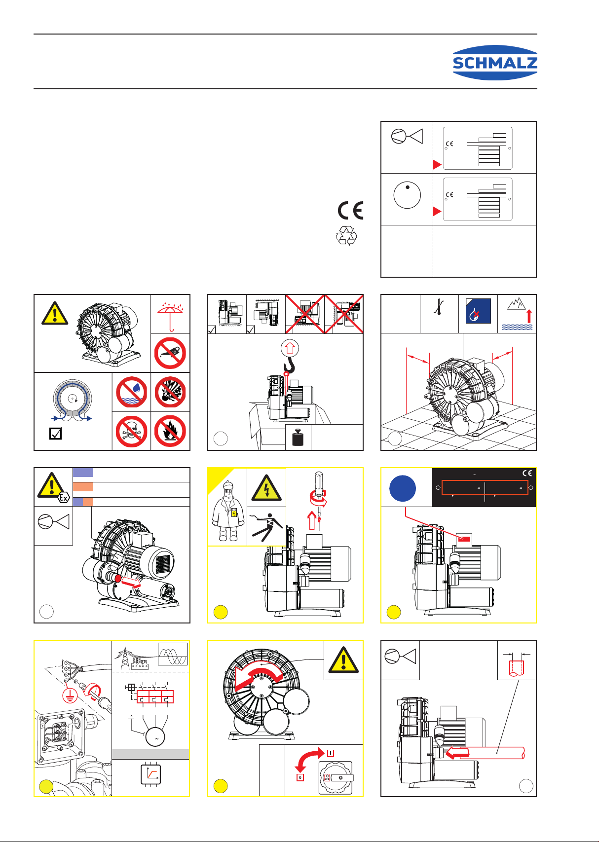
Instructions de sécurité
VeuillezrespecterlanormeDINEN1012-2
pourlespompesàvide.
Toutes transformations ou modications
des compresseurs à canal latéral ne sont
possiblesqu’avecl’accorddel’usine.
La forte compression de l’air entraîne
températuresélevéesjusqu’à125°C.Placer
lecompresseurdefaηonqu’ilsoitimpossible
d’avoir contact avec les surfaces brûlantes
oubien protéger la zonede circulation ou apposerdes
panneauxd’avertissement.
Lacompressiondel’airprovoquedestempératuresélevées:
Installerlecompresseurdefaçonàcequelespersonnes
nepuissentpastoucherlessurfacesbrûlantesouprotéger
lazonedecirculationdespersonnes,oubienapposerdes
panneauxd’avertissement.
Utilisation conforme à la nalité
Cecompacteurdecanalparallèlen’esthomologuéque
pourfonctionnerdansdessecteursdanslesquelsonest
enprésencequerarementoupouruncourtinstantd’une
atmosphèreexplosiveselonlacatégorie 3.
Le blower est équipés d’un moteur conformément à la
directive2014/34/UE.
Lecompresseuràcanallatéralestutilisépourgénérerdes
pressionsnégatives(vides)admise.
Les données spéciques gurant sur la plaque de type
sontvalablesjusqu’àunealtitudede800mau-dessusdu
niveaudelamer.
Ilestconηupouraspirerdesmélangesnonexplosibles.
Aucuneatmosphèreexplosiblenedoitpénétreràl’intérieur.
Iln’estpasprévupourlerefoulementoulacompression
deuidestoxiquesouinammables.
Exploiterlecompresseuràcanallatéraldefaηonqueseul
del’airatmosphériquepuisseêtreaspiré.Sidesuides
contenant des particules de poussière sont refoulés,
prévoir un ltre d’aspiration et exécuter des travaux de
maintenanceàintervallerégulier.
Respecterimpérativement les conditions d’exploitation
indiquéesdanslesspécicationstechniques.
Mauvais usage prévisible
L’utilisationn’estpasautoriséedanslescassuivants:
-Conditionsenvironnantesdanslesquellesilexistedesgaz
explosifsenpermanence,souventouoccasionnellement.
- Conditions environnantes dans lesquelles il existe
des poussières explosives en permanence, souvent ou
occasionnellement.
-Aspirationdegazoudepoussièresoùunétatexplosibleest
généréenpermanence,souventouoccasionnellement.
-Exploitationhorsdesconditionsd’exploitationindiquées
danslesspécicationstechniques.
Eviter impérativement que l’air évacué ne dépasse la
températurede125°C(135°C).
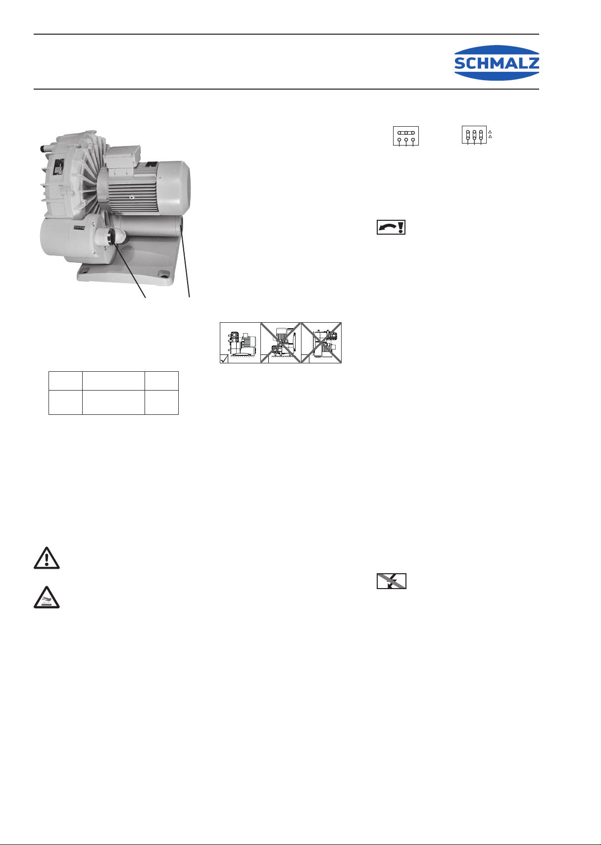
Transport et stockage
Stockerlecompresseuràcanallatéraldansunendroitsec
etàl’abridesprojectionsd’eau.
Soulever et transporter avec des sangles de transport
adaptées.
Mise en place
Placerl’appareilenplacedemanièreàcequelestravaux
demaintenance puissent être ultérieurement facilement
effectués.
optimalnonlicitenonlicite
L’espacelibreparrapportauxparoisvoisinesdevraêtre
d’aumoins 10 cm an de ne pas gênerle ux d’airde
refroidissement.
Lasoufantenedoitpasêtreinstalléedansdescapots
àinsonorisation.
Protégercontrelesdépôtsdepoussière.
Latempératureambiantenedoitpasdépasser40°Cvoire
sous-dépasser–20°C.
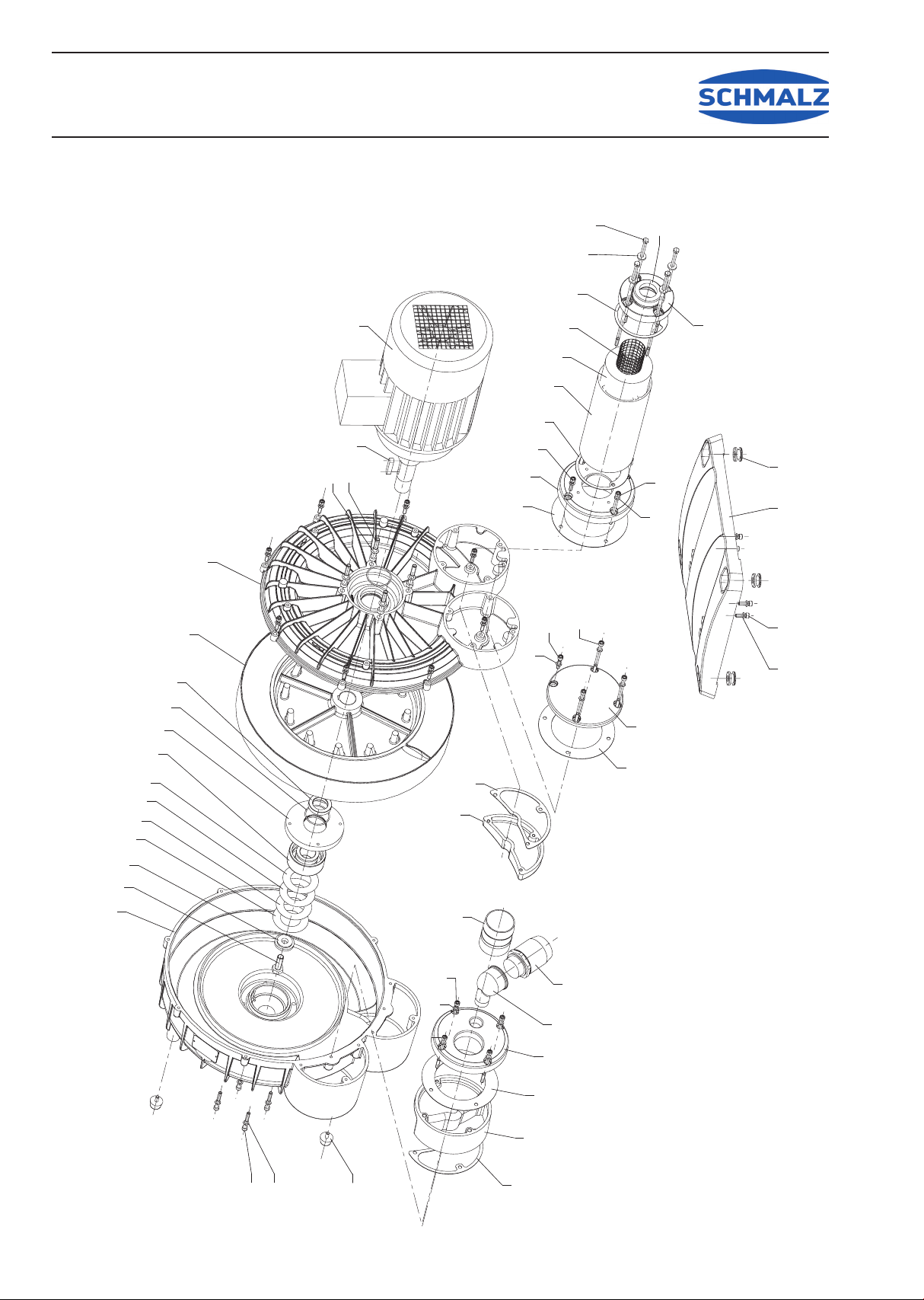
Lemontageducompresseuràcanallatéralnedoits’effec-
tuerqu’àl’horizontaleavecunpied.Auniveaudesalésages
dexation,lepieddelamachineestéquipéd‘éléments
amortisseursde vibrations (pos.204). Serrer lesvis de
xationdemanièreàcequelepiedn‘entrepasencontact
directaveclesol(écart=0,5mm).Lasurfaced‘appuidoit
êtreaussipourlasécuritéd‘Etatdegarantir.
Conditions d’exploitation
Eviter impérativement les températures de surface
dépassant125°C(50Hz)/200°C(60Hz).
Aceteffet,utiliserl’appareildanslesplagesdepression
indiquéessurlaplaquedetypeainsiquedanslaplage
admisedetempératureambiante.
LeBlowerSB-L-EXestconηuégalementpourunfonction-
nementcyclique.Ilfauts’assurerqu’encasd’uneduréede
sollicitation(=levagedelacharge)demax.60secondes,
unepausederepos(pendantlaquellel’appareilfonctionne
sanscharge)d’aumoins30secondesestrespectée.
Montage
Veilleràcequeledimensionnementsoitcorrectetàce
quelesconduitessoientpropres.
Protégerlecompresseurcontrelescorpsétrangers.
Lediamètredesconduitesdoitaumoinscorrespondreaux
letagesderaccordement.Au-delàd’unelongueurde2m,
nousrecommandonsd’utiliserlediamètreimmédiatement
supérieur.
Eviterquelesraccordementssoientcouvertsd’huile,de
graisse,d’eauoud’autressalissures.
EnleverlescapuchonsdeprotectionenDA et SANepas
encoreraccorderauréseaudetuyauterie.
Raccordement du moteur
Relier le compresseur à canal latéral au système
d’alimentationenénergiedefaηonàrespectertoutesles
prescriptionsapplicables.
Faireraccorderlemoteursuivantleschémademontage
(dans la boîte à bornes) ou les connexions à ches
prééquipéesuniquementparunélectricienqualié.
Tenir compte de la tension de raccordement et de la
fréquence.
Vériersilatensionsurplacedemandeunfonctionnement
en étoile ou un fonctionnement en triangle. Réaliser le
pontagecorrespondantdanslaboîteàbornes.
Condition:raccordementmaisonchamprotatifmagné-
tiqueàdroite
Prévoir un disjoncteur-protecteur et régler au courant
nominal du moteur (les données sont indiquées sur la
plaquedetypedumoteur).
Si des disjoncteurs-protecteurs et/ou d’autres organes
électriquessetrouventdanslazoneexplosible,ilsdoivent
êtreégalementhomologuésàceteffet.
Faire démarrer brièvement le moteur et
contrôlerlesensderotation(èchesurle
corps).Silesensderotationestincorrect,
intervertirlaphase.
L’utilisation du compresseur à canal latéral avec un
convertisseurdefréquencen’estpasadmise.
Eviterdefaireplusde10commutationsparheure.
Touteslespiècesmétalliquesdoiventêtremisesàlaterre
sur le lieu d’installation, en particulier en utilisant des
tamponsencaoutchouc.
Lesbandesoucâblesdemiseàterreadaptésdoiventêtre
installésparunspécialisteenéletricité.
Mise en service
Raccorderdefaηondurablementétanchelaconduitede
pressionàDAoulaconduited’aspirationàSA.
N’utiliserquedestuyauxhomologuéspour lessecteurs
explosibles.
Eviter les torsions mécaniques par les raccordements
detuyauxouxationsdecorpsenutilisantdesraccords
élastiques.
Contrôlerrégulièrementlescompensateursetlesconduites
pourlocalisertoutdéfaut,lecaséchéant,remplacer.
Si,pendantl’arrêtdel’appareil,ilestpossiblequedesuides
explosifspuissentpénétreràl’intérieurdelachambrede
compression,leclientdoitprendrelesmesuresnécessaires
pourl’éviterefcacement.
Lestempératuresdeserviceélevéesnonadmisessont
générées par des ltres d’aspiration colmatés (dans ce
cas,effectuerunemesuredemaintenance)ouparune
pressiondifférentielletropélevée.
Eviter impérativement les températures de surface
dépassant 125°C (50Hz) / 200°C (60Hz).A cet effet,
utiliserlecompresseuràcanallatéraldanslesplagesde
pressionindiquéessurlaplaquedetypeetendessousde
latempératureambiantemax.admise.
Maintenance
Unemaintenancerégulièredevotrecompresseuràcanal
latéral vous permet d’obtenir les meilleurs résultats de
travail.Lesintervallessontfonctiondel’utilisationetdes
conditionsenvironnantes.
Avantledébutdestravauxdemaintenance,
mettrelemoteurhorscircuitetempêcher
de manière able un redémarrage non
intentionnel.
Attendreaumoins60minutesavantd’ouvrirlesconduitesou
lecorpspouréviterlecontactaveclessurfacesbrûlantes.
Nettoyerrégulièrementlecapotdeventilateuretlessurfaces
ducompresseuretdumoteurpouréviterlessurchauffes
paraccumulationdepoussière.
Remplacerlespaliersàroulementdemoteurauplustard
après4ansou20.000heuresdeservice.
Installerleltred’aspirationdefaηonquelacartouchedu
ltresetrouveàl’horizontaleoumontreverslebasan
d’éviterquedelapoussièrenepénètredanslecompacteur
lorsdestravauxdemaintenance.Lesltresd’aspiration
doiventêtre conηus pour être utilisés dans lesecteur
explosible (voir instructions du ltre à poussière pour
secteurexplosible).
Entretien
Siunepièced’unappareilsoumiseàlaprotectioncontreles
explosionsestréparée,etqu’ellen’estpascontrôléeparla
suiteparlefabricant,l’appareilnepeutêtreremisenmarche
conformémentàl’ordonnancedesécuritéd’exploitationque
lorsqu’unbureaudecontrôlehomologuéouunepersonne
agrééeaexécutéuncontrôlecorrespondant.
Lemieuxestd’envoyerl’appareilaufabricant.
/
8 9 :
/ /
: 8 9
<9+]
<9+]
/
8 9 :
/ /
: 8 9
9+]
9+]
DA
SA
Fréquence Vide*Puissance
50 Hz
60 Hz
4,0 kW
4,6 kW
-375 (-475) mbar
-375 (-465) mbar

30.30.01.00158 Status 07.2017
Index 01
Schmalz Blower SB-L-EX
J. Schmalz GmbH
Johannes-Schmalz-Str. 1
D - 72293 Glaen
Tel +49 +7443 / 2403 - 0
Fax +49 +7443 / 2403 - 259
hp://www.schmalz.com
e-mail: [email protected]
Seite / Page 4/6
2 Ersatzteile / Spare parts / / Pièces de rechange

30.30.01.00158 Status 07.2017
Index 01
Schmalz Blower SB-L-EX
J. Schmalz GmbH
Johannes-Schmalz-Str. 1
D - 72293 Glaen
Tel +49 +7443 / 2403 - 0
Fax +49 +7443 / 2403 - 259
hp://www.schmalz.com
e-mail: [email protected]
Seite / Page 5/6
1
27
29
30
31
48
49
50
51
53
54
55
58
59
60
61
63
64
65
68
104
105
109
116
117
118
119
121
122
123
124
181
182
183
185
187
188
201
202
204
215
305
316
318
400
400
MOTOR 1)
LAGER(MOT)
GEHÄUSE
DICHTUNGSSCHLAUCH
FEDERSCHEIBE
INNENSECHSKANTSCHRAUBE
PASSFEDER
LAUFRAD
DISTANZBUCHSE
LAGERDECKEL
LAGER
SPANNSCHEIBE
WELLENENDSCHRAUBE
ZWISCHENLEGRING
ZWISCHENLEGRING
ZWISCHENLEGRING
ZWISCHENLEGRING
GEHÄUSEDECKEL
FEDERSCHEIBE
INNENSECHSKANTSCHRAUBE
DICHTUNG
DECKEL
INNENSECHSKANTSCHRAUBE
DICHTUNG
SCHALLDÄMPFERGEHÄUSE
SIEBROHR
DÄMPFER
GEWINDEFLANSCH
UNTERLEGSCHEIBE
ZUGANKERSCHRAUBE
DÜSE
DICHTUNG
REDUZIERSTÜCK
DECKEL
DECKEL
INNENSECHSKANTSCHRAUBE
GERÄTEFUSS
UNTERLEGSCHEIBE
KABELTÜLLE
GUMMIPUFFER
DECKEL
WINKEL
SCHLAUCHSTUTZEN
VAKUUMREGULIERVENTIL2)
VAKUUMREGULIERVENTIL3)
MOTOR 1)
BALLBEARING(MOT)
PUMP BODY
SEAL
SPRINGDISC
SOCKETHEADSCREW
KEY
IMPELLER
SPACER
BEARINGCOVER
BALLBEARING
CLAMPINGDISC
SHAFTENDSCREW
SPACER
SPACER
SPACER
SPACER
HOUSINGLID
LOCKINGWASHER
SOCKETHEADSCREW
SOCKETHEADSCREW
GASKET
COVER
SOCKETHEADSCREW
GASKET
SILENCERHOUSING
STRAINERTUBE
SILENCERSPONGE
FLANGE
WASHER
SCREW
NOZZLE
GASKET
REDUCINGPIECE
COVER
COVER
SOCKETHEADSCREW
SOCKETHEADSCREW
FOOT
WASHER
RUBBERBUSHING
RUBBERBUFFER
COVER
ELBOW
HOSECONNECTOR
VACUUMREG.VALVE2)
VACUUMREG.VALVE3)
Pos Beschreibung Description Designation
MOTEUR 1)
ROULEMENTABILLES(MOT)
CORPDEPOMPE
JOINT
DISQUEDERESSORT
VISHEXAGONALEINTERNE
CLAVETTE
ROUE
DOUILLEETANCHEITE
COUV.DEROULEMENTE
ROULEMENTABILLES
DISQUEDESERRAGE
VISBOUTD‘ARBRE
DISQUEAJUSTAGE
DISQUEAJUSTAGE
DISQUEAJUSTAGE
DISQUEAJUSTAGE
COUVERCLE
RONDELLEÀRESSORT
VISHEXAGONALEINTERNE
JOINT
COUVERCLE
VISHEXAGONALEINTERNE
JOINT
CORPSDELASILENCIEUX
GRILLEPOURSILENCIEUX
MOUSSEPOURSILENCIEUX
BRIDE
RONDELLE
VIS
GICLEUR
JOINT
PIECEDEREDUCTION
COUVERCLE
COUVERCLE
VISHEXAGONALEINTERNE
PIED
RONDELLE
PROTECTIONENCAOUTCHOUC
AMORTISSEURENCAOUTCHOUC
COUVERCLE
COUDES
CONNEXIONTUYAU
SOUPAPEREGLAGEVIDE2)
SOUPAPEREGLAGEVIDE3)
Bestell-Nr. / Ident No. /
No.Identication
42635222416132
201101 00019
000102 41600
91131000000
951707 00000
94533700000
947742 00000
000600 41600
01390041600
001100 41600
201101 00017
016800 41600
901806 00000
91143300000
91143400000
91143500000
91143600000
000202 41601
95170300000
94532700000
94532200000
110205 10092
005602 41600
94537300000
907500 19600
007400 19600
907600 60000
110205 10087
007800 19600
949451 00000
90380401000
95312200000
11020510093
015500 41600
005601 41600
005600 41600
94537100000
94532000000
110205 10089
947504 00000
210502 00117
74131500000
00560341600
30060009000
93920135000
73600399624
73600999624
1)Drehstrommotor,SchutzartIP55
Spannungen:
400/230V//50Hz,bzw.
480/280V//60Hz
Leistung4/4,6KW
2) eingestellt auf 50 Hz-Betrieb
3) eingestellt auf 60 Hz-Betrieb
1)Moteurtriphasι,modedeprotectionIP55
tension:
400/230V//50Hz,respectif
480/280V//60Hz
Puissance4/4,6KW
2)ajusterà50 Hz mode
3)ajusterà60 Hz mode
1)Three-phasemotor,typeofprotectionIP55
voltage:
400/230V//50Hz,respectively
480/280V//60Hz
Capacity4/4,6KW
2) set to 50 Hzoperation
3) set to 60 Hzoperation

30.30.01.00158 Status 07.2017
Index 01
Schmalz Blower SB-L-EX
J. Schmalz GmbH
Johannes-Schmalz-Str. 1
D - 72293 Glaen
Tel +49 +7443 / 2403 - 0
Fax +49 +7443 / 2403 - 259
hp://www.schmalz.com
e-mail: [email protected]
AA
A> 100mm
A> 4" > -15°C/-4°F
< 40°C/104°F
max.
800m
max. 90%
%
Betriebsanleitung
Operating Instructions
Instructions de service
Istruzioni d’uso
Handleiding
Instrucciones para el manejo
Manual de instruções
Naudojimosi instrukcija
Kasutusjuhend
Lietošanas instrukcija
Οδηγίες χρήσης
取扱説明書
사용설명서
Driftsinstruks
Driftsinstruktioner
Käyttöohje
Driftsvejledning
Instrukcja obsługi
Kezelési útmutató
Návod k obsluze
Navodilo za uporabo
Návod na obsluhu
El Kitabi
Инструкция по
эксплуатации
使用说明书
Softstart
U
t
L1 L3
L2
L2 L1 L3
I >I >I >
U1 V1 W1
M
3
OPTIONAL
-p
VACUUM
Ø 60mm
2))
21
0$;
[K
7
-p
VACUUM
50Hz
60Hz
≤ -375mbar ► 24h
E
x II 3G/3GD c IIB 125°C (T4)
MAX -475mbar ► max. 60s
Ex II 3G/3GD c IIB 200°C (T3)
MAX -465mbar ► max. 60s
+
Mat.Nr. XXXXXX ENXXXX
3 Mot. XXXXXXXX
NoUD XXXXXX XX
XX kg
50 Hz
XXKW
XXX-XXX / XXX-XXX
V
/Y
XX-XX / XX-XX
A
XXXX-XXXX /min
cos 0.XX-0,XX
60 Hz
XXKW
XXX-XXX / XXX-XXX
V
/Y
XX-XX / XX-XX
A
XXXX-XXXX /min
cos 0.XX-0,XX
i+
AIR
62 kg
137 lbs
34 5
68
MAX.
V
m /h
3
Made in Germany
year
No
min-1
kW
m /h
3
mbar
type
speed
power required
inlet capacity
max. pressure
Hz
frequency
MAX. V
MAX.
-p
VACUUM
mbar
Made in Germany
year
No
min-1
kW
m /h
3
mbar
type
speed
power required
inlet capacity
max. vacuum
Hz
frequency
MAX. VACUUM
L = 74 dB(A) - 50Hz
L = 77 dB(A) - 60Hz
K
= 3 dB(A)
pA
pA
pA
DIN EN
ISO 3744
1 2
2006/42/EG
DIN EN ISO 14001:2005
Seite / Page 6/6
Table of contents
Languages:
Other Schmalz Blower manuals
Popular Blower manuals by other brands

Graphite
Graphite 58G031 instruction manual

Scheppach
Scheppach LB2500P Translation from the original instruction manual

Bosch
Bosch DHG602DUC installation instructions

Meyer
Meyer VERSA-VAC Operation & maintenance instructions

Zephyr
Zephyr PBN-1000A Use, care and installation guide

Solo
Solo Port 423 Original instructions

Simco-Ion
Simco-Ion I-VSE 5000 Installation and operating instructions

Master
Master MAC-701-DR User's manual and operating instructions

Nilfisk-Advance
Nilfisk-Advance SW 700S B Technical specification

Ryobi
Ryobi RY09056 Operator's manual

Electrolux
Electrolux Icon E48DD75ESS installation instructions

Weed Eater
Weed Eater BV1850 instruction manual