Bedienungsanleitung FMP(-S)-SVK / FMP(-S)-SW
Operating Instructions FMP(-S)-SVK / FMP(-S)-SW
30.30.01.01009 Status 01.2018 / Index 4
J. Schmalz GmbH
Johannes-Schmalz-Str. 1
D - 72293 Glatten
Tel +49 (0) 7443 / 2403 - 0
Fax +49 (0) 7443 / 2403 - 259
www.schmalz.com
schmalz@schmalz.de
2
Inhaltsverzeichnis / Contents
1. Sicherheits- und Gefahrenhinweise / Safety notes and warnings ..............................................................4
1.1 Verwendete Symbole / Symbols used................................................................................................................4
1.2 Allgemeine Sicherheitshinweise / General safety instructions............................................................................4
1.3 Bestimmungsgemäße Verwendung / Intended use............................................................................................6
1.4 Besondere Gefahren / Specific hazards.............................................................................................................6
1.5 Hinweis für den Benutzer des FMP(-S)-Greifers / Instructions for users of the FMP(-S) gripper........................7
2. Installation und Anschlüsse / Installation and connections........................................................................7
2.1 Befestigung am Handlingsystem / Attaching to the handling system..................................................................7
2.2 Vakuumanschluss und Manometer / Vacuum connection and gauge ................................................................7
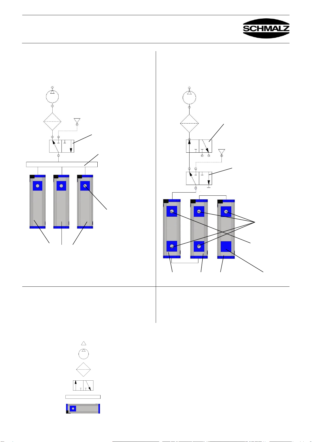
2.2.1 Pneumatische Schaltung FMP für externe Vakuumerzeugung –SW-Version / Pneumatic circuit FMP
for external vacuum generation –SW version....................................................................................................7
2.2.2 Pneumatische Schaltung FMP für externe Vakuumerzeugung –SVK-Version / Pneumatic circuit FMP for
external vacuum generation –SVK version........................................................................................................7
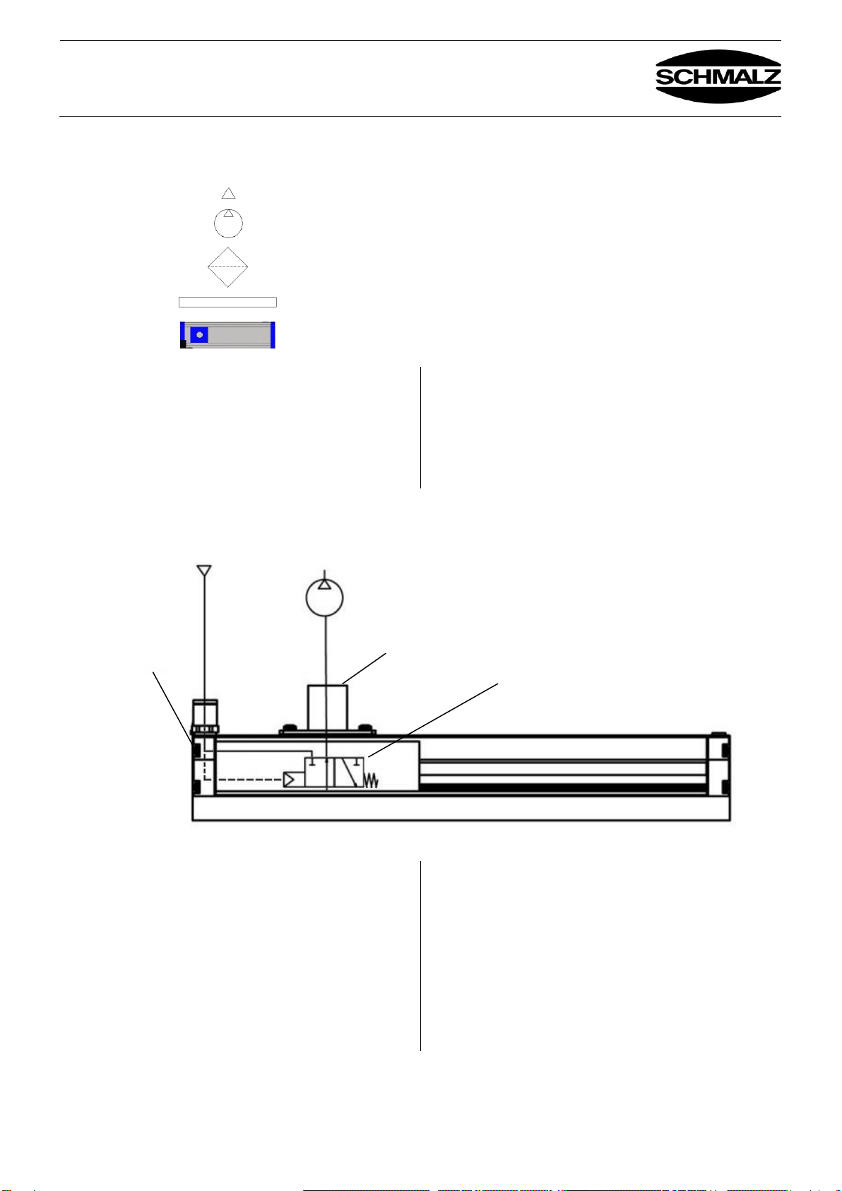
2.2.3 Pneumatische Schaltung FMP-S für externe Vakuumerzeugung –SW / SVK-Version / Pneumatic circuit
FMP-S for external vacuum generation –SW / SVK version..............................................................................9
2.3 Anschluss Druckluft FMP-S Greifer / Compressed air connection for the gripper FMP –S..............................12
2.4 Anschluss Druckluft Abblasimpuls / Connecting the compressed air blow-off pulse ........................................12
2.5 Anschluss Druckluft Vereinzelung / Connecting the compressed air separation ..............................................14
2.6 Elektrischer Anschluss und LED-Anzeige FMP-S / Electrical connection and LED indicator for FMP-S..........15
2.6.1 Elektrischer Anschluss FMP-S / Electrical connection for FMP-S ....................................................................15
2.6.2 LED-Anzeige / LED indicator............................................................................................................................15
3. Funktionsbeschreibung / Description of functions....................................................................................16
3.1 Funktionsbeschreibung –Komponenten / Description of functions –Components..........................................16
3.2 Funktionsbeschreibung Ventiltechnik SVK / Description of functions: SVK valve technology .........................22
4. Montage einzelner Komponenten / Mounting individual components .....................................................23
4.1 Montage Dichtplatte / Mounting the sealing plate.............................................................................................23
4.2 Montage Saugeranschlussleiste / Mounting the suction pad connection strip..................................................23
4.3 Montage Ventilfolie (SW und SVK –Folie) / Mounting the valve film (SW and SVK film).................................24
4.4 Montage FMP-S Vakuumventil / Installing the vacuum valve for the FMP-S....................................................25
5. Wartung / Maintenance..................................................................................................................................27
5.1 Wartungsplan / Maintenance plan....................................................................................................................29
6. Fehlersuche / Troubleshooting.....................................................................................................................31
7. Technische Daten / Technical data...............................................................................................................33
7.1 Technische Daten Flächensauggreifer FMP-S / Technical data for the area gripper FMP-S ...........................33
7.2 Abmessungen bei FMP(-S) mit Dichtplatte / Dimensions for FMP(-S) with sealing plate.................................34
7.3 Abmessungen bei FMP(-S) mit Sauger SPB2 / Dimensions for the FMP(-S) with suction pad SPB2..............35
8. Zubehör, Optionen / Accessories and options............................................................................................37
8.1 Bausatz Befestigungskit Roboterflansch / Robot flange attachment kit............................................................38
8.2 Bausatz Befestigungskit Aufhängung / Suspension attachment kit ..................................................................38
8.3 Bausatz Elektromagnetventil Abblasen / Attachment kit for solenoid valve for blow-off ..................................39
8.4 Bausatz Aufhängung FST STARR / FST STARR suspension kit.....................................................................40
8.5 Bausatz Aufhängung FST FLEX / FST FLEX suspension kit............................................................................40
8.6 Bausatz Saugerleiste für Einschraubsauger 1/8"AG / Suction pad strip kit for screw-in suction pads 1/8"
male thread.......................................................................................................................................................41
8.7 Abdeckleiste für seitliche T-Nut / Cover strip for T-slot on side ........................................................................41