Schmalz SCPS Series User manual

Innovative Vacuum for Automation
EN
Operating instructions
Compact ejector SCPS
30.30.01.00422/05 | 07.2018

SCHMALZ SCPS
CONTENTS
1Safety Instructions.................................................................................................... 1-4
Important symbols........................................................................................................................1-4
General safety instructions...........................................................................................................1-4
Intended use................................................................................................................................1-5
Installation and operation .............................................................................................................1-6
2Product Overview...................................................................................................... 2-7
General description of functions...................................................................................................2-7
Vacuum generation (picking up the workpiece).............................................................................2-7
Blow-off (depositing the workpiece) ..............................................................................................2-7
Vacuum/pressure display.............................................................................................................2-8
Versions.........................................................................................................................................2-8
Ejector version PNP or NPN.........................................................................................................2-8
Electrical connection ....................................................................................................................2-8
Ejector design................................................................................................................................2-9
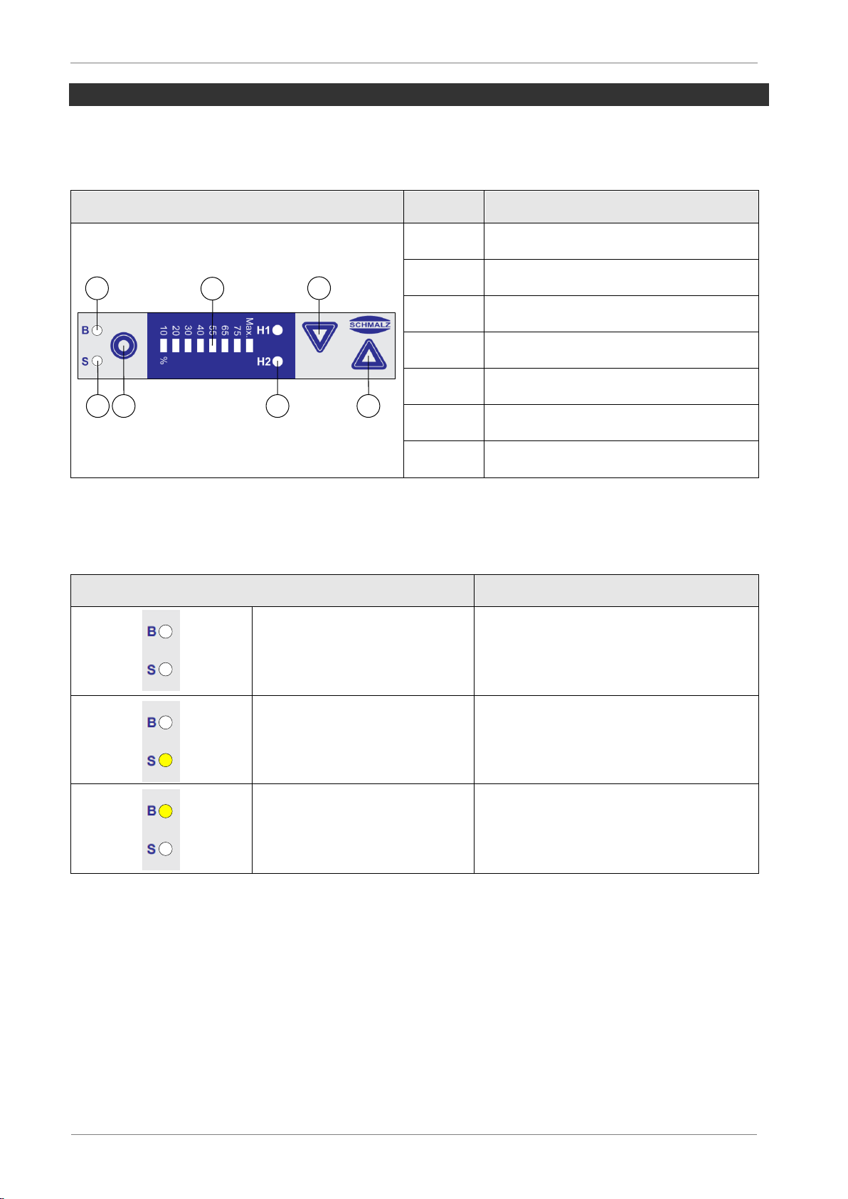
Operating and display elements .................................................................................................2-10
3Description of Functions........................................................................................ 3-12
Operating modes..........................................................................................................................3-12
Ansteuerung Ejektorvariante NO................................................................................................3-14
Ansteuerung Ejektorvariante NC ................................................................................................3-14
General functions.........................................................................................................................3-15
Manual mode.............................................................................................................................3-15
Monitoring the system vacuum...................................................................................................3-16
Control function..........................................................................................................................3-16
Blow-off modes ..........................................................................................................................3-16
Signal output..............................................................................................................................3-16
Vacuum unit...............................................................................................................................3-17
Operating voltage display...........................................................................................................3-17
Locking the keypad....................................................................................................................3-17
Setting the blow-off volume flow.................................................................................................3-17
4Operation and Settings........................................................................................... 4-18
Viewing and setting parameters..................................................................................................4-18
Overview of the operating structure ...........................................................................................4-19
5Operation.................................................................................................................. 5-20
Overview....................................................................................................................................5-20
Mounting....................................................................................................................................5-20
Pneumatic connection................................................................................................................5-21
Electrical connection ..................................................................................................................5-22
Pin assignment of the connection plug........................................................................................5-23
Projektieren................................................................................................................................5-23
Start of operations......................................................................................................................5-24

SCHMALZ SCPS
6Maintenance............................................................................................................. 6-25
General maintenance...................................................................................................................6-25
Exterior soiling ...........................................................................................................................6-25
Silencer......................................................................................................................................6-25
press-in filters.............................................................................................................................6-25
Warranty, spare parts and wearing parts....................................................................................6-25
Spare and wearing parts ............................................................................................................6-26
Troubleshooting...........................................................................................................................6-26
Accessories..................................................................................................................................6-27
7Technical Data ......................................................................................................... 7-28
Electrical parameters...................................................................................................................7-28
Mechanical data...........................................................................................................................7-29
General parameters ...................................................................................................................7-29
Materials used............................................................................................................................7-29
Mechanical parameters..............................................................................................................7-29
Dimensions................................................................................................................................7-30
Pneumatic circuit diagrams.........................................................................................................7-31
8Conformity Declaration .......................................................................................... 8-32

SCHMALZ SCPS
1-4
1 SAFETY INSTRUCTIONS
IMPORTANT SYMBOLS
This symbol indicates important information and instructions.
Caution!
This symbol indicates a potentially dangerous situation.
If it is not avoided, slight or minor injuries may result.
Danger!
This symbol indicates an immediate hazard.
If it is not avoided, death or serious injuries may result.
GENERAL SAFETY INSTRUCTIONS
These operating instructions contain important information on using the ejector. Please
read the operating instructions thoroughly and keep them for later reference.
Never look into any open or closed vacuum vents (e.g. vacuum connec-
tions or suction pads).
Serious injuries could occur as a result. Eyes can be sucked in.
Compressed air can cause closed containers to explode. A vacuum can cause closed
containers to implode.
The ejector may only be operated with a silencer. Never look into the exhaust air jet of
the silencer.
The ejector emits noise. We recommend wearing ear protection.
This device is not intended for use with hazardous dust, oil mist, vapors or aerosols, etc.
If drawn in, these materials will enter the exhaust air and may result in poisoning.
Use only the connections, mounting holes and attachment materials that have been pro-
vided.
Carry out mounting and removal only when the device is in an idle, depressurized state.
No person may sit or stand in the area in which the load is to be transported.
No person may sit or stand in the danger zone while the machine or system is in auto-
matic mode.
Components may be installed by trained specialist personnel only.

SCHMALZ SCPS
1-5
Specialist personnel must be familiar with current safety rules and requirements. For ex-
ample, these apply to the use of components such as solenoid valves and pressure
switches as well as to controllers used in devices, machines and systems.
Specialist personnel must also be familiar with the system’s control concept. In particu-
lar, they must be familiar with the system’s redundant control components and feedback
signals.
INTENDED USE
The ejector is designed to generate a vacuum for gripping and transporting objects when
used in conjunction with suction pads. Neutral gases in accordance with EN 983 are ap-
proved as evacuation media. Neutral gases include air, nitrogen and inert gases (e.g. argon,
helium and neon). Aggressive gases or media such as acids, acid fumes, bases, biocides,
disinfectants or detergents are not permitted.
The ejector is not suitable for transporting or sucking through liquids or bulk ma-
terial such as granulates.
Personal injury or damage to the ejector may occur.

SCHMALZ SCPS
1-6
INSTALLATION AND OPERATION
For safe installation and trouble-free operation, please observe and comply with the follow-
ing points:
The ejector may only be operated using power supply units with protected
extra-low voltage (PELV). The system must incorporate safe electrical cut-
off of the power supply in compliance with EN60204.
Do not operate the ejector in environments where there is a risk of
explosion.
Risk of fire and explosion.
Output signals (discrete signals as well as IO-Link signals) can change
when the power supply is switched on or the M12 connectors are plugged
in. Depending on the function of the machine/system, this can result in
serious personal injury or damage to the equipment.
The device may not be operated outside its specified performance limits.
Doing so may cause it to malfunction or be destroyed.
During installation and maintenance, make sure that the ejector is disconnected
and depressurized and that it cannot be switched on again without authorization.
Personal injury or damage to the ejector may occur.
Protect the ejector from damage at all times.
No modifications may be made to the ejector.
Opening the ejector will damage the “tested” labels. This voids the warranty.
Connection symbols and labels are located on the ejector.
These must be observed.
Only the intended connections may be used.
Pneumatic and electrical line connections must be securely connected and attached to
the ejector.
The ejector may be installed in any position.
If these instructions are not observed, malfunctions, material damage and serious injury
–including fatal injury –may result.
If the ejector is no longer operative, the components must be disposed of in an ecologi-
cally sound manner.

SCHMALZ SCPS
2-7
2 PRODUCT OVERVIEW
GENERAL DESCRIPTION OF FUNCTIONS
VACUUM GENERATION (PICKING UP THE WORKPIECE)
The ejector is designed for vacuum handling of parts in combination with suction systems.
The Venturi nozzle is activated and deactivated via the suction signal input. In the NO ver-
sion, the Venturi nozzle is deactivated when the suction input signal is present. In the NC
version, the Venturi nozzle is activated when the suction input signal is present.
An integrated sensor records the vacuum generated by the Venturi nozzle. This is evaluated
by an electronics system and serves as the basis for displaying the system states and
switching the output.
The ejector has an integrated air-saving function. The ejector automatically regulates the
vacuum while in suction mode. The electronics system switches the Venturi nozzle off when
the switching point H1 set by the user is reached.
If small volumes are to be evacuated, the set switching point H1 might be ex-
ceeded considerably before the vacuum is switched off. This system behavior
does not constitute an error.
When objects with dense surfaces are picked up, the integrated non-return valve prevents
the vacuum from dropping. If leakage causes the system vacuum to drop below the switch-
ing point H1-h1, the Venturi nozzle is switched on again.
BLOW-OFF (DEPOSITING THE WORKPIECE)
In blow-off mode, the vacuum circuit of the ejector is supplied with compressed air. This en-
sures that the vacuum drops quickly, depositing the workpiece quickly as well. Blow-off
mode can be controlled externally or internally.
When controlled externally, blow-off mode is activated by the “blow-off” signal input.
When controlled internally (automatic blow-off), the blow-off valve is actuated for a defined
period after suction mode is exited.
The ejector also has a manual mode. In this mode, the ejector can be controlled
using the buttons on the ejector’s foil keypad. See the “Manual mode” section for
more details.

SCHMALZ SCPS
2-8
VACUUM/PRESSURE DISPLAY
The current system vacuum is always displayed in the 8-digit LED bar display. The 2 LEDs,
H1 and H2, indicate which range the vacuum level is in relative to the threshold
values set.
VERSIONS
Each ejector has a specific item designation (e.g. SCPS-10-G2-NO-M12-5-PNP).
The item designation can be broken down as follows:
Type
Perfomance
class
Pneumatic
connection
Idle position
Electrical
connection
Signal input /
Signal output
SCPS
07
10
15
G2
(2x G1/8”)
NO
Normally open
NC
Normally closed
M12-5
(1xM12, 5-pin)
NPN
PNP
EJECTOR VERSION PNP OR NPN
The switching properties of the ejector’s electrical inputs and output are permanently set on
the device, meaning they are independent of the version.
Input
Output
NPN
PNP
ELECTRICAL CONNECTION
The electrical connection is established using a 5-pin M12 connector that supplies the ejec-
tor with voltage, and contains the two input signals and the output signal. The inputs and
outputs are not electrically isolated from one another.

SCHMALZ SCPS
2-9
EJECTOR DESIGN
Only screw unions with cylindrical G-threads can be used at pos. 4 and pos. 8.
We recommend using washers on the mounting holes.
Do not look into the exhaust outlet (compressed air) during operation!
Position
Description
Max. tightening
torque
1
Process state display: suction/blow-off
2
Controls
3
Blow-off valve screw
4
G1/8" vacuum connection (label: 2 [V])
4 Nm
5
M12 electrical connection
Hand-tight
6
Controller
7
Mounting holes
2 Nm
8
Compressed air connection
G1/8" in H version (label: 1 [P])
4 Nm
9
Silencer cover
0,5 Nm
10
Exhaust outlet (label 3)
3
4
1 5
6
8
7
9
10
2

SCHMALZ SCPS
2-10
OPERATING AND DISPLAY ELEMENTS
The foil keypad with the LED bar and 4 additional LEDs allows for very simple operation of
the ejector.
Position
Description
1
LED-bar
2
LEDs for threshold values H1 / H2
3
MENÜ - button
4
UP - button
5
DOWN - button
6
LED process state: suction
7
LED process state: blow-off
PROCESS STATE LEDS
The process states „Suction“ and „Blow-off“ are each assigned an LED.
Process state LEDs
Ejector status
LEDs are both off
No suction on ejector
Suction LED
is continuously lit
Ejector is in suction state or being con-
trolled
Blow-off LED
is continuously lit
Ejector blows off
5
1
7
4
236

SCHMALZ SCPS
2-11
LEDS FOR THRESHOLD VALUES H1/H2
The LEDs for the H1 and H2 threshold values indicate the current level of the system vacu-
um relative to the configured switching points.
Threshold value LEDs
Ejector status
LEDs are both off
Rising vacuum:
Vacuum < H2
Falling vacuum:
Vacuum < (H2-h2)
H2 LED is continuously lit
Rising vacuum:
Vacuum > H2 and < H1
Falling vacuum:
Vacuum > (H2-h2) and < (H1-h1)
LEDs are both continuously lit
Rising vacuum:
Vacuum > H1
Falling vacuum:
Vacuum > (H1-h1)
ADDITIONAL DISPLAY FUNCTIONS
Display
Meaning
Max. - LED lights up briefly
Supply pressure present,
otherwise no LED is active
10% - LED flashes rapidly
Vacuum < permitted range
(for example, during blow off)
Entire LED bar lights up
Max. - LED flashes rapidly
Vacuum > permitted range
Max. - LED flashes rapidly
Supply pressure
> permitted range

SCHMALZ SCPS
3-12
3 DESCRIPTION OF FUNCTIONS
OPERATING MODES
The ejectors are differentiated according to their start position when in the idle state: NO
(normally open) and NC (normally closed).
When the ejector is connected to the power supply, the ejector is in automatic mode and
ready for operation. This is the normal operating mode, in which the ejector is operated by
the system controller.
In addition to automatic mode, you can also change the operating mode of the ejector to
manual mode using the buttons on the foil keypad.
Parameterization of the ejector is always performed in automatic mode.
A U T O M A T I C –M O D E
P A R A M E T R I Z A T I O N
M A N U A L M O D E

SCHMALZ SCPS
3-13
A U T O M A T I C –M O D E
P A R A M E T E R I Z A T I O N
Suction OFF
Auto blow-off
NC, NO
Blow-off ON
NC, NO
IN2 = on
M A N U A L M O D E
Blow-off
Suction ON
NC : IN1 = on
NO : IN1 = off)
Suction OFF
NC : IN1 = off
NO : IN1 = on
Blow-off OFF
NC, NO:
IN2 = off
Pneumatically OFF
Pneumatically OFF
NC:
Power
failure
NO: Power failure
Suction
Venturi-
nozzle
active
Venturi-
nozzle
inactive
Vacuum
H1
Vacuum
<H1-h1
Air-saving function
Blow-off
Suction Air-saving function [ctr = on]:
Vacuum H1
Vacuum < H1-h1
Venturi-
nozzle
active
Venturi-
nozzle
inactive
Change in
External
signal
No
button
> 2 min
> 3s

SCHMALZ SCPS
3-14
ANSTEUERUNG EJEKTORVARIANTE NO
ANSTEUERUNG EJEKTORVARIANTE NC
1
0
0bar
- p
1
0
0bar
p
„ Suction“ [IN1]
„ Blow-off“ [IN2]
„Suction“ Mode
„Blow-off“ Mode
1
0
0bar
- p
1
0
0bar
p
„ Suction“ [IN1]
„ Blow-off“ [IN2]
„Suction“ Mode
„Blow-off“ Mode

SCHMALZ SCPS
3-15
GENERAL FUNCTIONS
MANUAL MODE
The output signals may change during set-up in manual mode.
Ensure that the machine or system does not start moving as a result.
Personal injury or damage to the ejector could result.
Starting manual mode always switches the ejector to “pneumatically OFF” mode.
In other words, starting manual mode interrupts an active suction process.
Danger due to falling parts.
In manual mode, the pick-up and blow-off ejector functions can be controlled independently
of the higher-level controller using the buttons on the operating panel.
In this operating mode, the H1 and H2 LEDs both flash.
ACTIVATING MANUAL MODE
Activate manual mode as follows:
Press and hold the and buttons together for more than 3 seconds
MANUAL SUCTION
In manual mode, suction is activated by pressing the button. Exit suction mode by
pressing the button again or by pressing the button.
If the air-saving function is activated this is also activated in manual mode.
MANUAL BLOW-OFF
Blow-off mode is activated in manual mode by pressing the button. This mode remains
active as long as the button is pressed.
DEACTIVATING MANUAL MODE
Exit manual mode using the button.
The ejector also exits manual mode when the statuses of the external signal inputs change.
This automatic exiting of manual mode due to changes in external signals can
cause the object being handled to move (due to suction or blow-off).

SCHMALZ SCPS
3-16
MONITORING THE SYSTEM VACUUM
Every ejector has an integrated sensor for monitoring the current system vacuum. The vac-
uum level provides information on the process and has an effect on the following signals
and parameters:
Threshold value LED H1
Threshold value LED H2
Signal output H2
CONTROL FUNCTION
This ejector function allows you to conserve compressed air. Vacuum generation is inter-
rupted once the configured threshold value H1 is reached. If leakage causes the vacuum to
fall below the hysteresis threshold H1-h1, vacuum generation resumes.
The control function can be deactivated by setting the threshold value for H1 to “Max.”.
BLOW-OFF MODES
EXTERNALLY CONTROLLED BLOW-OFF
The blow-off valve is controlled directly via the blow-off signal input. The ejector switches to
blow-off mode for as long as the signal is present.
INTERNALLY TIME-CONTROLLED BLOW-OFF
The “Blow-off” valve is automatically activated for the time period set as soon as the ejector
leaves the “Suction” mode. This function makes it possible to save an output on the control-
ler.
The time-controlled blow-off is activated by setting a value greater than zero for
the blow-off time.
SIGNAL OUTPUT
The ejector has a signal output.
OUTPUT FUNCTION
The signal output is a normally open (NO) contact and cannot be changed.
The signal output is switched on or off when the system vacuum is higher or lower than the
relevant threshold value.

SCHMALZ SCPS
3-17
VACUUM UNIT
The vacuum level in the LED bar is shown as a percentage of the maximum possible vacu-
um.
If the vacuum is outside the permitted range, the LED next to this bar will flash rapidly. That
means the LED flashes “10%” when overpressure is applied.
OPERATING VOLTAGE DISPLAY
In operating modes in which no LEDs are activated, the “Max” LED will light up briefly. This
indicates an operating voltage.
LOCKING THE KEYPAD
Pressing the and keys at the same time locks the keypad. Pressing both keys again
unlocks the keypad.
SETTING THE BLOW-OFF VOLUME FLOW
There is a valve screw below the vacuum connection (2). This valve screw can be used to
set the blow-off volume flow.
Turning the screw clockwise reduces the volume flow. Turning the screw counterclockwise
increases the volume flow.
The valve screw is equipped with a stop on both sides.
Do not turn the valve screw past the stops. A minimum volume flow of approx.
10% is always necessary for technical reasons.
The blow-off volume flow can be set between 10% and 100%.
+
-

SCHMALZ SCPS
4-18
4 OPERATION AND SETTINGS
The three keys on the foil keypad are used for operation and setting the parameters. If no
parameters are set, the ejector is in display mode. The current vacuum is displayed.
If settings are changed, this can cause undefined changes to the system status
for a shot period of time (approx. 50 ms) in certain situations.
VIEWING AND SETTING PARAMETERS
The following parameters can be set for the ejector:
H1 threshold value for the controller
H2 threshold value for the signal output
Blow-off period for time-controlled blow-off
The hystereses for the threshold values are pre-defined.
LED-bar
H1
h1
H2
h2
Blow-off time
10%
-
-
100 mbar
10 mbar
20 ms
20%
200 mbar
40 mbar
200 mbar
10 mbar
50 ms
30%
300 mbar
60 mbar
300 mbar
10 mbar
100 ms
40%
400 mbar
80 mbar
400 mbar
10 mbar
250 ms
55%
550 mbar
110 mbar
550 mbar
10 mbar
500 ms
65%
650 mbar
130/75 mbar *
650 mbar
10 mbar
750 ms
75%
750 mbar
150/75 mbar*
750 mbar
10 mbar
1000 ms
Max
Control desabled
-
-
1500 ms
*If a value > (H1-h1) is selected for H2, the hysteresis h1 will be dynamically adjusted so
that (H1-h1) is 25 mbar above H2.
The value set for H1 must always be greater than the value set for H2. Only set-
tings that meet this specification can be made.
For H1, the hysteresis is always 20% of the H1 value; the hysteresis h2 is always 10 mbar.
By pressing the key, you can view the first parameter (threshold value H1). If you press
the key again, the second parameter (threshold value H2) and the third parameter (blow

SCHMALZ SCPS
4-19
off time) are displayed. You can use the and keys to change any parameter. Press
the key again to exit the setting mode.
The LEDs assigned to the parameters flash to indicate which value is currently being dis-
played or changed.
LED
Parameter
Parameter for H1 is being displayed or changed
Parameter for H2 is being displayed or changed
Parameter for blow off time is being displayed or changed
The value will flash briefly to indicate that a changed parameter is being applied.
OVERVIEW OF THE OPERATING STRUCTURE

SCHMALZ SCPS
5-20
5 OPERATION
OVERVIEW
During operation of the ejector, all input and output signals are connected to a controller,
either directly or using intelligent terminal boxes.
For this purpose, not only the supply voltage but also two input signals and one output sig-
nal should be connected to allow the ejector to communicate with the controller.
With these connections, the basic functions of the ejector can be used, including suction,
blow-off and feedback signals. The individual connections are as follows:
Ejector inputs
Ejector output
Suction ON/OFF
Blow-off ON/OFF
Feedback H2
The parameters are set via the operating and display elements.
MOUNTING
SCPS …
We recommend using washers when mounting the securing screws.
Position
Description
Max. tightening torque
1
M4 securing screw
2 Nm
2
Top-hat rail clamp for TS35 top-hat rail, incl.
plastic tapping screws (optional)
0,5 Nm
1
2
Other manuals for SCPS Series
2
This manual suits for next models
1
Table of contents
Other Schmalz Vacuum Cleaner manuals