Montage
Suite à la manœuvre positive d’ouverture des contacts lors de
l’actionnement du volet de sécurité, les entraînements de la machine
s’arrêtent. Ceci empêche la blessure du personnel ainsi que
l’endommagement des composants de la machine qui se situent
derrière le volet de sécurité.
Pour effectuer l’entretien, le profil de sécurité peut être verrouillé
en position horizontale. En exerçant une pression sur ses côtés
supérieurs saillants, le volet est ramené en position de base.
L’interrupteur de position n’est pas inclus dans le kit de montage.
Pour les types appropriés, voir Données Techniques : Eléments de
commutation. La position optimale de fonctionnement et de monta-
ge est obtenue, si le contact à ouverture de l’interrupteur de position
présente une manœuvre positive d’ouverture après une course du
volet de sécurité de 7,5 mm (voir dessin). Afin d’obtenir cette situati-
on, le montage est à effectuer comme suit
1. Vissez la vis de centrage M8 à filetage auto-taraudant à gauche
et à droite dans le profil de sécurité.
2. Marquez la position des trous oblongs de l’interrupteur de posi-
tion à l’entraxe L2 sur le profil support. La rainure transversale
indique la ligne de fixation inférieure. Forez des trous pour des
vis, filetage M5.
3. Fixez une plaque latérale au profil support à l’aide de 3 vis auto-
taraudantes M6.
4. Placez l’entretoise sur la vis de centrage. Insérez le profil de
sécurité dans le trou de forage de la plaque latérale, placez la
deuxième plaque latérale et fixez-la au profil support à l’aide
de 3 vis M6.
5. Vissez l’interrupteur de position à l’aide de deux vis M5 x 40.
6. Positionnez le volet de sécurité sur le dessous des plaques
latérales. Mettez le volet en position de commutation à l’aide
d’une entretoise, h = 12,5 mm. Ajustez l’interrupteur de position
à l’aide d’un générateur de signaux optique ou acoustique de
sorte que le contact à ouverture est ouvert.
7. Serrez les vis de fixation de l’interrupteur de position. Forez et
goupillez le trou rond supérieur pour sécuriser l’interrupteur de
position contre tout déplacement.
8. Vissez les deux loqueteaux de maintien aux plaques latérales à
l’aide de vis plastites N° 7 x 12. Encliquetez le profil de sécurité
et serrez les vis.
9. Fixez le volet de sécurité dans la position désirée au corps de la
machine.
10.Afin de garantir l’étanchéité IP 67 de l’interrupteur de position, il
faut utiliser une entrée de câble appropriée, éventuellement avec
soulagement de traction. Les bouchons utilisés par nous sont
uniquement prévus comme protection anti-poussière pendant le
transport. Section de câble maximale 2,5 mm2y compris les
embouts éventuels.
K. A. Schmersal GmbH
Montage
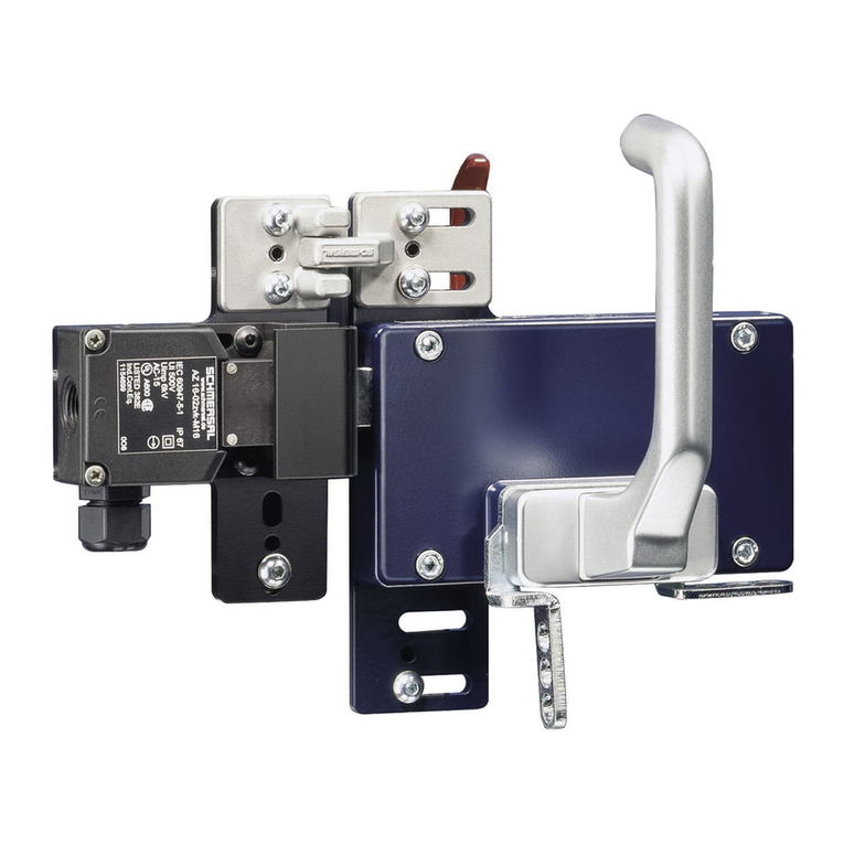
The positive break action of the contacts upon actuation of the
safety flap stops the machine drives. In this way, the personnel is
protected against injury and the machine components located
behind the safety flap against damage.
For service purposes, the flap profile can be fixed in horizontal posi-
tion. If its upper protruding sides are pushed, the flap returns to its
basis position. The position switch is not included in the mounting
set. For appropriate types, refer to Technical Data: Contact blocs.
The optimal operational and mounting position is reached, if the NC
contact of the position switch has a positive break after a 7.5 mm
travel of the flap profile (see drawing). To obtain this situation, the
mounting is to be carried out in the following way:
1. Screw the centring screws M8 with self-tapping thread to the
right and the left in the flap profile.
2. Mark the position of the slotted holes of the position switch at
the centre distance L2 on the carrier profile. The transversal
groove indicates the lower fixation line. Drill M5 thread holes.
3. Fix a side plate to the carrier profile using 3 screws M6 with
self-tapping thread.
deutsch
english
français
4. Put the spacer onto the centring screws. Insert the flap profile in
the borehole of the side plate, install the second side plate and
fix to the carrier profile using 3 screws M6.
5. Fix the position switch using two screws M5 x 40.
6. Put the safety flap at the bottom of the side plate. Bring the flap
in switching position using a spacer h = 12.5 mm. Adjust the
position switch with an optical or acoustic signal generator in
such a way that the NC contact is opened.
7. Tighten the fixing screws of the position switch. Bore and pin the
upper round hole to secure the position switch against
displacement.
8. Screw two stops to the side plates using plastite screws nr.
7 x 12. Clip in the flap profile and tighten the screws.
9. Fix the safety flap in the desired position to the machine body.
10.In order to guarantee protection class IP 67 of the position
switch, an appropriate cable entry, eventually with pull relief is to
be used. The plugs used by us exclusively serve as anti-dust
protection during transport. Max. 2.5 mm2cables including
possible conductor ferrules.
Montage
Infolge der zwangsweisen Öffnung der Kontakte bei Betätigung der
Sicherheitsklappe werden die Maschinenantriebe stillgesetzt. Somit
werden das Bedienpersonal vor Unfällen und die hinter der Sicher-
heitsklappe liegende Maschinenteile vor Beschädigungen geschützt.
Zu Servicezwecken kann das Klappenprofil in horizontaler Lage ein-
gerastet werden. Durch Druck gegen die vorstehende Oberkante
der Klappe wird die Ausgangsposition wieder erreicht.
Im gelieferten Bausatz ist der Positionsschalter nicht enthalten.
Geeignete Typen siehe Technische Daten: Schaltelemente.
Die optimale Funktions- und Einbaulage ist dann gegeben, wenn
der Öffnungskontakt des Positionsschalters nach einem Hub des
Klappenprofiles 7,5 mm zwangsöffnet (siehe Zeichnung). Um dies
zu erreichen, ist die Montage folgendermaßen auszuführen:
1. Zentrierschrauben M8 rechts und links in das Klappenprofil ein-
drehen. Das Gewinde formt sich selbst.
2. Lochbild der Langlöcher des Positionsschalters im gewünschten
Abstand L2 auf das Trägerprofil übertragen. Die Längsrille gibt
die untere Befestigungslinie an. M5-Gewindelöcher bohren.
3. Eine Seitenplatte mit 3 Schrauben M6 am Trägerprofil befestigen.
Das Gewinde formt sich selbst.
4. Distanzscheiben auf Zentrierschrauben stecken. Klappenprofil in
Lagerbohrung der Seitenplatte fügen, zweite Seitenplatte auf-
stecken und mit 3 Schrauben M6 am Trägerprofil befestigen.
5. Positionsschalter mit zwei Schrauben M5 x 40 handfest
anschrauben.
6. Sicherheitsklappe auf die Unterkante der Seitenplatten stellen.
Mit einem Distanzstück h = 12,5 mm Klappe in Schaltstellung
bringen. Positionsschalter mit Hilfe eines optischen oder akusti-
schen Signalgebers so justieren, dass der Öffnerkontakt gerade
geöffnet ist.
7. Befestigungsschrauben des Positionsschalters fest anziehen.
Zusätzlich das obere Rundloch aufbohren und verstiften, um
den Positionsschalter gegen Verrutschen zu sichern.
8. Zwei Rastungen mit Plastiteschrauben Nr. 7 x 12 an den Seiten-
platten handfest anschrauben. Klappenprofil einrasten und
Schrauben fest anziehen.
9. Sicherheitsklappe in gewünschter Position am Maschinenkörper
befestigen.
10.Um die Schutzart IP 67 des Positionsschalters zu gewährleisten,
ist eine entsprechende Leitungseinführung, gegebenenfalls mit
Zugentlastung, zu verwenden. Die von uns eingesetzten Stopfen
dienen nur als Staubschutz beim Transport. Maximaler Anschluss-
querschnitt 2,5 mm2einschließlich evtl. Aderendhülsen.
