manuals.online logo
Brands
  1. Home
  2. •
  3. Brands
  4. •
  5. ADEMCO
  6. •
  7. Security Sensor
  8. •
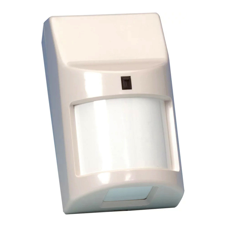
  9. ADEMCO 5775 User manual

ADEMCO 5775 User manual

N4390V3 7/91
+
fXDEMcOl
INSTALLATION
INSTRUCTIONS
No. 5775
PASSIVE INFRARED
MOTION DETECTORfTRANSMITTER
IMARGIN LINES INDICATE PRINCIPAL CHANGES
/_ IN THIS ISSUE +
GENERAL INFORMATION
The No. 5775 Passive Infrared Motii OetecfofTranWffer is ab-anew
operaled. wireless device interrded for use as Part of a5700 Se~es
Wireless Alarm System, and provides wide angle coverage with 9
detection zones, with arange of Up1035 feel.
This document provides installation insfrucfiins for the No. 5775, but
il is recommended Ihat the installer also be familiar with the Installation
Inslrucfions for the 5700 Series Receiver/Conlroi.
FEATURES
oAduaf element pyre-electric sensa provides positive protection
while minimizing false alarms.
oAfternate polarity pulse count opfiin offers grealer stability in
adverse environments.
.Walk Test LED for added ease of system checkout.
.Removable battery compartment drawer for easy battery
replacement without the need 10 remove the unit’s cover.
●Convenient wall or corner mounting options
.Wireless operation for fast and easy installation.
.Pet alley mounting option.
SYSTEM DESCRIPTION
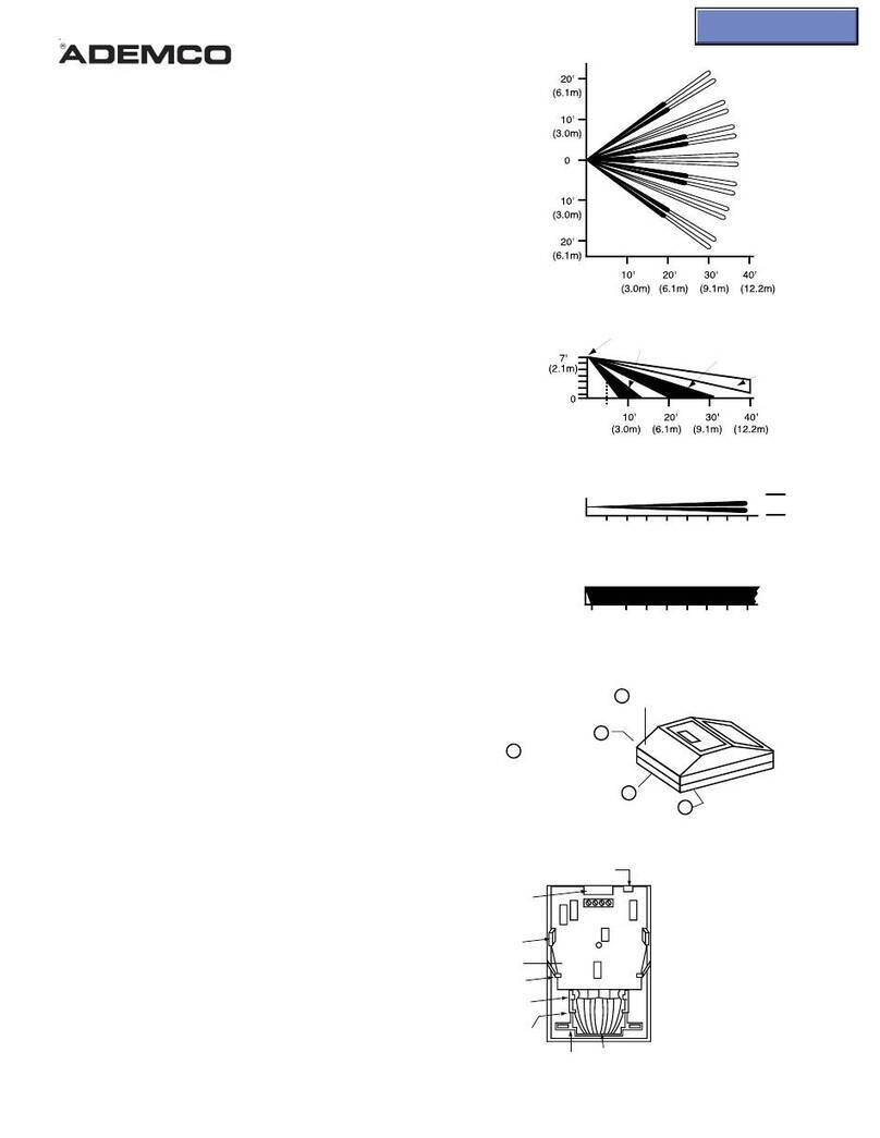
Optical System: The No. 5775 uses a~mputer designed optical
system which divides the protected area into aseries of six wide-angle
zones. spanning atotal angle of S4” from the detector, and three
downward angled zones, which provide overlapping coverage to the
fkror level (refer 10 diagrams 1&2). Adual element pyro-elacfric
sensor within the No. 5775 measures the level of infrared energy in
each zone, and detects any changes therein. When an infruder
crosses or enters any zone, the resulting change in infrared energy
triggers an alarm. The alarm is then transmitted to the system’s
Receiver Control where itis prrxessad. Since far infrared energy does
not penetrate most budding materials (including window glass), the
No. 5775 responds only to movements inside the room or protected
area.
Radio Transmitter: The built-in transmitter serves only as the
communication link to the system’s Receiver/Control. His nof used
for detection purposes. Thus, more than one detector can be used in
the same area, Radio messages sent from the deteclor”s Transmitter
to the syslem”s ReceiverK20ntrof uniquely identify the detector, and
also contain appropriate alarm, supervisoryor low battery information.
ADIP switch located on the main PC board is used to program the
required “House ID” and “Transmiffer IV numbers (described in the
system’s Installation Instructiws). To conserve battery life, no more
than one transmission sequence will occur within any three minute
period. During the ‘cover off”test mode, however, transmissions are
not time restricted.
Alternate Polarity Pulse Count Oplion: The NO 5775 provdes IWO
DIP swdch se@clable delecllon response males Instant Response
and Alternale Polanfy Pulse Count When set fOr Instanl Res+mrma,
any detecled change minfrared energy ~n tfgger an Immediate
alarm. Thts mode IS recommended when @detector IS used to
rnomtor ahalfway or long cornctor, where dwII detect an intruder’s
presence Immediately upon entry Insfant mode ISalso useful durrng
mstallabon wafk tests.
The Pulse Count option can be used mprolecreu areas where pencxlc
changes minfrared energy levels are normal (a forced aw heating
duct, for example). When selected. adefected change minfrared
energy is first verified before an alarm is fnggered The venfntmn
process requires that the sensor detect at %st IWOconsecutive
changes in infrared energy within agwen tune perod, before
generating an alarm.
IMPORTANT! Ifthe Pulse Count option is desired, be sure towalk lest
the unit while ItISsef for Pulse Count operatim to ensure the proper
operation of the unit whale in this mode.
‘i;iL?? Oeledion Are#
TOP VIEW
[al 7Fl i2 IM) Mwnmq lieqmj
10FT
[3MI
o
10FT
(3M)
20 FT
16M) &loFr 20FT 30FT 35Fr
[3M) (6M) (9M) (105M)
V/IX AREA
PATTERN
DETEcTIoN AREA
7FT ISIDE VIEW
‘2’M)~
o3FT IOFT %“FT
‘(9M) [3M) :~05M)
OEAD
ZONE
[APP130X)
Diagrams 1&2. PROTECTION PATTERNS
INSTALLATION PRECAUTIONS
Refer to the Pre/imirrary Locafiorr r%Wo’era/ioas section of the 5700
Series System Installation Instructions for additional information
concerning precautions for the system’s ReosiverCcrntrol.
Unprotected “Dead Zone”’: The optical system is designed to givw
pmparcoverage based on atypical mounting height of 7feet (2. 1m).
There is, however, an area from the mounting wall toabouf three feet
(0.9m) away, wifhin which motion goes undefeated (shown in
diagrams 1&2). This area is known as a dead zone. Be sure 10
consider Ibis area when deciding on mounting locations.
finding Suitable Locations: Since the No. 57T5 responds to en
intruder’s movements into or out of aprotected zone, best protection
will be obtained by selecting amounting site where an intruder’s
motion will most fikefy be across anumber of zones.
Asfrong radio transmission path 10the Receivevt%ntrol isvital tothe
security of the system. &fore deciding on parmanenf mounting
focations, be sure that the location is cornplektysuitable by performi~
the %dio Transmission Path Check described bter in this document.
Passive infrared detectors are remarkably resistant 10 false alarms,
but since they are designed to respnd to ra@d changes in infrared
energy levels, the precautions shown befow should be taken for
oplimum performance.
2
Inf!i
‘x
Iml
T==n I
:
r
f% not Iflstall where the detector IS
exposed to direct sunlight or dtrectly
above strong sources of heal.
Make sure Ihe detecIlon area does not
have obstrucfjons (curiaIns, screens.
large preces of furnrture, plants. etc.)
which may block the pattern of coverage.
Avoid krcating aund mareas which
Conlain objects tikefy topro&x araptd
change mtemperature, such as cenfral
heating, radiators or ducts (or twatera Of
any kind), air conditioners, open flame,
etc,
nstall the detector at aheight of
JpProxlmatefy 7feet (2m) from floor. 00
lot mOLJnton an unstable surface.
PRELIMINARY SETUP PROCEDURES
1
2.
3.
4.
DIP Switch Setting and Battery Installation:
Remove the No. 5775 front rxwer by prying dwith acoin or
screwdriver at the notch shown in d“iagram-3.
Set the DIP switch located on the ~board within the unit for the
assigned “House ID” and Transrmtfer ID- numbers as described
in the Receiver/Control Installation Instructions. Refer 10dtagram 3.
Remove the battery compartment drawer by slkting it out from
the bottom of the unit and install one fresh 9voii battery (see
Specifications and Note for Lithium flattery Users sections for
battery types).
Replace the battery compartment drawer, but do not replace the
front cover at this ~me. After approximately two minufes, the
detector will be activated, and will transmit u~rr detection Of
motion. The Walk Test LED will also fiiht.
Selecting Pulse Count Operation:
If Pulse Count operation is desired, set DIP switch 10 to the ON
position as shown in diagram 3. Afarms will be triggered orrfy if the
sensor detects mutfiple changes in infrared energy (Le. After an
intruder has taken 3or 4steps within the prolecwd area). The OFF
positkrrr provides Instant Response (i.e. Alarms trigger the instant an
intruder is detected).
MOUNTING THE NO. 5775
Radio Transmission Path Check: Verifythal astrong transmission
palh between the No. 5775 and the system’s Receiver/Control exists
before making permanent inatallatiin. This is accomplished by
performing the Pre/imina~ r%gfammingbcdiorr Test described in
the system’s Receiver/Conlrol Installation Instructions. The No. 5775
will transmit when sensing motion (waving arm or walking into area).
Sometimes, moving the detector onfy afew inches means the
difference between astrong and weak transmission path. Experiment
until you are satisfied that the location provides the strongest
transmission path, while still being practical for the protection pattern
desired. This test also serves to verify correct DIP switch settings.
lMPORTANTf Do not install aNo. 5775 permanently, until astrong
radio transmission path to the Rea?iver/Control has been achieved.
Normal Mounting:
1. Oetermine asuitable location which provides best protection
coverage and strong rad~ tranamissii to the Receiver/Control.
2. Remove the battery compartment drawer. Remove the No. 5775
from its mounting case by gently spreading both sides of the case
(a screwdriver can be used) and ring the mryjule wt.
3. Three knockouts are provided for flat wall mounting; four are
provided for corner mounting (refer to the hrveried Mounfirg
Spacer diagram). Punch out the appropriate knockouts for the
mounting desired.
4. Mount the case tcra firm, vertical surface (fiat wail or corner) at
the desired iocation using #4 parrhead screws.
IMPORTANT! Make sure the PiR’s case is flush againsf the wall
(when flat or comer mounted), and do not Lwt@ghferr fhe mounting
screws. Failure to C.@rve this precaution may cause the case 10
distorf and result in the PIRs module becoming distodgedlater.
5. Snap the No. 5775 into the mounting case and replace the
battery drawer.
6. With the front cover removed, perform the walk test described in
the Wdk Test section. 3
1In
+i“OVER
BATTERY
COMPARTMENT
e
m
\hcuNm4G
INSERT SCREWDIWVER CASE
SLAOE HERE
ANo TWIST
WALK TEST
LEO
HUPC BOARD II
I
MIRROR
i.D.
32
33
34
35
36
37
3a
39
40
41
42
43
44
45
46
47
TRANSMITTER 10
SWITCH POSITIONS
6789
on on on On
on on on OFF
on Ofi OFF on
on on OFF OFF
on OFF on on
on OFF on OFF
OP OFF OFF on
on OFF OFF OFF
OFF on on
OFF 0, 8F F
OFF 0, YFF on
OFF OP OFF OFF
OFF OFF on
OFF OFF on 8F F
OFF OFF OFF on
OFF OFF OFF OFF
—
1.1
I
—
1
2
3
4
:
7
8
9
10
11
1?
13
14
Is
,6
17
18
19
m
21
?2
r?
?4
?5
6
17
s
9
u
C+F c?4
HcwsE 10
SW 1.5
(S-H FCXi 1.31:
TRANSh4rTTE R
10 w69
(SET FC+73247
PUSE CXXJNT
CPTION
m4=
PLSSECXXN7
OFF .
NSTIhl
RESPCt4SE
HOUSE ID
SWITCH POSITIONS
1?345
on on o“ OFF
on on On &FF 00
on on on OFF OFF
on on OFF on on
0+7 on OFF wOFF
on o“ OFF OFF or!
on on OFF OFF OFF
on OFF On
on OFF on ~YFF
on OFF on OFF on
on OFF on OFF OFF
on OFF OFF o.
on OFF OFF on YFF
on OFF OFF OFF c,”
on OFF OFF OFF OFF
OFF on on on on
OFF on on O. OFF
OFF on OFF on
OFF on :OFF OFF
OFF on OFF on
OFF on OFF on &FF
OFF on OFF OFF on
OFF on OFF OFF OFF
OFF OFF on o“ ~“
OFF OFF ~on OFF
OFF OFF on OFF on
OFF OFF on OFF OFF
OFF OFF OFF On on
3FF OFF OFF 011 OFF
OFF OFF OFF OFF on
>FF OFF OFF OFF OFF
J
Oiagram 3. No. ~5 OIP SWITCWPULSE COUNT OPTfON
PET ALLEY MOUNTING OPTiONS
ffsmaft pefshaveac03as to protected areas, one of the fol~
mourifingopfions SJM3ukfbeuaedtoprevent pet acfivatedfafsaatarms.
Each of these optii affera fhe pattern of protection SUL%that smafI
animals wifl not be detected.
WARNiNG! When using the pat alley option% acrawting intruder
Wfflalso be undetsdad.
4
Normal mounlmg wllh masked mwroropllon. TneceIecIo~ can@
mounted ncxmally al 6feet (18m) from the floor Wth the downwacd
pom!mg pxtion of Ihe mirror masked
IMPORTANT! This ophon IS vahd ontyfor rooms LJP1015 fl X15 ft
14 5m x 4 5m) msize
1Mask the mjrror using electrical of maskmg tape as shown m
diagram 4
2Mounl Ihe detector usng normal mountmg procedures ala he!ght
o16ff (1 ftm)
[3Check that no motion is delected wthin 31~2ff (f m) of the floor
Using the No. 1875PA Pet Alley Mirror: Th6 opl~on mmor can be
used mheu of maskmg the exmtmg mmor, Refer 10 Its mstallalton
mstructons for details To replace the mvror
(f r--1 11
M-J
1’ ~
r,=
,=
d
II
10PC BOARD 1
1
2
Spread either of both plasbc
prongs hohlng the wide
angle mirror and remove
the mmr
Inserl one sde of the No
1875PA mmor under a
prong and snap the other
sde under lhe other prong.
Make sure thal the mirror
sides are squarely mtheir
comer rests and are held
securely under the prongs
NOTE: Mirror sudace should
be free of dwt. Iore!gn matter
and fmgerprmls Use aclean
dry soft cloth to wipe mrror
surfaces if requwed.
b~O-ffi< (HOLD MIRROR IN WE)
Inverted Mounting Option: The detector can be mounted
approximately 3ff to 35 H. (O 9 – 1m) from the floor man mverfad
position (PIR window at top), wllh spacers attached to the mounting
case. When mslalled in Ibis manner, the portion of the mirror which
normally piowdes adownward beam of protection now provides an
upward pomlmg beam.
Before mounting inverted, note the following:
.Be sure that furniture and other objects do not block the detector’s
pattern of protection.
.[fpossible. install adetector sothatitisml directedatceilingareas
that include heating or air-conditioning ducts, vents, ce!lmg fans or
lighting fixiures. If these sources of infrared energy or turbalenca
cannal be avo{ded, the upward pamtmg beams must be masked 10
avwcf the possibility of false alarms. To mask the mirror, remove
the fronl cover and apply electrical tapa or masking tape as shown
below:
.Ver#y that the bcation provides astrong radio transmission path to
the Recewer Control as described earlier.
f, Attach the spacers to the detector as follows
a. Ifmounhng to flat wall: Assemble the two spacers, one above
the other. and affix the combination to the area of the mounting
case shown in diagram 4.
b. Ifmountmg macorner: affix one spacer to the rear of each of the
corner mowsfmg sales of the mounlmg case. as shown in
diagram 4.
2. Mount the detector mounting case upsidedown approximately 31/2
feet (1m) above the floor using the procedure desatbed earfier.
3. Check that no motion is detected within 31/2 feet (1m) of theffaor.
BATTERYCOMPARTMENT
II10FIA::NYLo
KNOCKOUTS (3III
SE SURETO COVERONLY-WE AREASHOWN
Diagram 4. INVERTEDIPET ALLEY MOUNTING
5
WALK TEST
fRefer to lhe Location Test sechon Of Ihe system’s Insla”:a:ca
Inslructons for addtlonal mformallon)
NOTE: The No 5775 requwes aIwo-mfnute “warmup- period after
applyng ~wer.
1.
2.
3
4.
Remove the front cover from Ihe No 5775 (lo permfl more than
one Vansmlsslon every 3mmutes). Set und to Pulse Cam! @e
If that aphon is 10 be used.
Pface the system’s Receiver Control inlo Test Mode
Walk mlo the protected area. The Walk Tesl LED will hghl whef
the deteclor senses your motion, and the Recewer Control WIII
sgnal the deteclors alarm Iransmissian (typically by SCUndmg
audible beeps at Ihe Keypad).
R@ace cover and verify aperation at the keypad.
No~e: LED WIIInot fght wfthcover in pface, but ihe transrrufter ID
Wbe displayed at the keypad when the detector IS faulted
MAINTAINING PROPER OPERATION
In onler to maintam the detector in proper working condd}cm. dIS
Impcaanl that the following be observed by the user,
1
2
3
Power musl be provided at all limes. A9V Alkaline battery shoulc
supply enough power for up to 1-1/2 years” of oparatton normally
A9V IAhwm battery may last up to 4years.” Refer to the
Specifiitions section for factors affecting actual banery life man
installation. However, abattery must be replaced wnhm 30 days
of afow battery indication at the Receiver/Controfk console.
The No. 5775 should never be re-aimed or relocated wjthwt th~
adwce of the alarm serwce company.
The ohvsical surroundings of the rxolecled area WIII affect the
Pattern’of protection if c;anged afier the time of installahon. For
example. If furniture IS moved. or alr-condltlonmg or acfdwonat
heating is installed, the system may have to be readjusted bythe
alarm service company 10 ensure proper prelection.
4.
Nole thal with the No. 5775 front cover in rYace. onlv one alarm
WaJk tests should ‘be conducted fiequent~ (at least weekly) to
mnfirm the proper coverage by each detector. This is accompfishec
by selecting the Test Mode at the Receiver Control’s console.
walking through Ihe pratected area, and noting the alarm condit]on
dis@ayed at Ihe ReceiverControl”s console.
transmission will be transmitted wilhin eve~ three m-inuie period
“UL Listed installations are currently approved for 1year battery fife c
TROUBLESHOOTING
PROBLEM
MCitesInto Alarr
Fw NOAcQwenl
Reason.
Wad Cows@
*S Char@
hsro0asr401
QP-loh
2pafabng
PROBLEM CAUSE IREMEDY
Rspd changeminfrad
energykwalsinme of Iha
pruadad areas Someot
L&se scurces are elecrnc
or gas haalefs, open Itsmae.
e!ecrnc arcs. wany ebjecls
*may be parlially ma
zma and can ciwrue
Iaqafature ra@d~.
Sinkorothersmallanimals
are enksnng me afea.
IdwWy the sOWcs dma
tnfraaderwgywl-a.
lureCtIarqaRa.pmtim ma
detacror so Ir!althe mm
lsnobrgafrn apfmaci.sd
Zona,lrthe sourcacarmx
t.s Ilw4ad.
Elirrsnaleall FCSMS e-sty
pores Iorlxrds, cals, Ocgs,
rcdanls, erc Chnlad erssf.
mmstcs Ifnacassaw
Userhasre-peirkonad tvr-
rnlufemaprokclecl area. Cam ueerurachaqas
In Iayvul cm afladcovwsgs
Ra-aimorrekxafesladdauu
aaordirg toinsraltaam
mvwrcos 5scananrlw
rhedaredwhssnorbasn
ranwaradW.
Mounhq surfaceisunstsb+e.
Afewc@mesWtliCd 5hifl
can change raw
Subsrardklly
Urleisnorfecaiwrg
power.
MOLHIlthedatedorma
eratdeeuffaok
Chadks qmplara barrel-y
Vdrsga.tf!sralnawbme-yfl
necessary,irusmgikhmm
balterresseaMa kf urwm
Serrarytkars bakx -
Note for Llthlum Battery Users
The manufacturer has advised us that lithium batteries have a
normal tendency to show low voftage after storage (to prolong shelf
life), due to an increase in capacitance from non-use.
Once abatlery is put into use, or the battery terminals are shorted
for about 5secwrds, preferably with a 10 ohm wire round resistor (a
minor paper dip vAffsuffii), the voltage restores to about 9.5 volts,
6
Jt-LLIt IL AI I(-)NS
D,menstona:
Weight.
OSleCliOn Method:
Coverage:
Oetecuon Zones:
Pulse Count:
Delectable Walk Rate:
Mounting Height:
Transmit Frequency:
Transmission Range:
I
Input Voltage:
Operating Humidity:
Operaling Temperature:
3q,,. Wx31. Hx ~-D
(? ScmW I97ant4 x53cmC
70 02 1200 g,amsj Mm X-Y,
5402 (1S) garn5) wthew ~-q
Passwe Infrared
35H (106mix45fl (137r-, Macge
9zones (6 bqr 3ahoq
Inslaller oplmn
Os-sn seczmd(o!5. !* w.,
7f! nermnal (2 lm)
345MHz (U S)315MH2 fCa-#~,
I00 tt Mrm )mrnmsl
OrW 9V A!kaiire battery, Memo No 4S4
Eveready 522. 0vrac8S MN 1624 ‘wovdmq
up to 1-1/2 years of Me], of one 5V Lrfhwm
battery. Ademce No 465 [PWW5.9 up 104
years et Me) ““See No/e forLitWIT $arfery
Users below Tmdeskuow secmn
up to 95*0 f++ {max )--a ~%
32%= to t22’F [m 10 WI
I““ Lcqewty dbsttenes wit dapenduponlhe efm’romnersaM qExternal
Iacsofs such as humdi?y hgh mlow temperatures, as we+ ss leqw swings n
le~falure. may ail reduce the ScUJSlOanwy Me magr+m Instal&-
UL LIsled ns!al!atmns are currently aWov@ bIyear banq de W+Y
IMPORTANT! PLEASE NOTE THE FOLLOWING:
Before any equipment is returned 10 ADEMCO for saoce, aReturn
Authorization Number should first be obtawwd from the nearest
Ademco Distribution Center.
If it becomes necessaty to return aunit for rqxir. the optcal head
and reflector assembly w!thin the unrt should be cuslwmed by
surroundingitwithsoftpacking malerial (such as tissue, newspaper,
foam or plastic bubbles) to protect it from undue stressduring
shipment. Take care not to touch the reflector or sensessurfaces.
TO THE INSTALLER
Regular maintenance and inspection (at least annually)byrheinstaller
and frequent testing by the user are vital to ccmtinuoussatisfactory
operalion of any alarm system.
The installer should assume the responwbifityof deve+qmg and
offering aregular maintenance prcgrarn 10the user .s3well as
acquainting the user with the propar operation and fimifafionsof the
alarm system and its cnmponent parts. Recomme@a6cms mustbe
incfuded for aspecifc program of fraquenl testing (at least weekly)
to insure the system’s proper operation at all times
THIS DEVICE COMPLIES WITH PART 15 OF FCC RULES. ANY
INTERFERENCE THAT MAY BE CAUSED SHOULD BEREPORTED
TO ADEMCO, CUSTOMER SERVICE, 165 EILEEN WAY,
SYOSSET, N.Y., 11791, (516) 921-6704.
WARNING
THE LIMITATIONS OF THIS PASSIVE
INFRARED MOTION DETECTOR
While the Intrusion Detector is ahighly reliable intrusiondetection
device, it does not offer guaranteed protectii against burglary.
Arty Intrusion Detection device is subject to compromise or failure
to warn for avariety of reasons:
.Pasaive Infrared Motion Detectors can onfy dated infrusion
within the designed ranges as diagramed in this installation
manuaf.
.Passive Infrared Motion Oetedors do not pro+%%volumetric
area prohsctiort.Ttseydo create muffipfe beams of Protedion,
and intrusioncan onfy be detected in unobstructed areas omered
by fhoSS t3S8tIW.
●Passive Infrared Detectors cannot detect motion or intrusion
that fakes place behind wafls, ceifings, ftoora, cfosed doors,
glass partifiis, glass doors, or windows.
●Mechanical tampering, masking, painting or spraying of any
material on the mirrors, windows or arty part ofthe opticalsystem
can reduce the detection ability of the PassiveInfrared Motion
Detector.
●Passive Infrared Detectors sense changes in temperature; how-
ever, as the ambient temperature of the ~otect~ area ap-
proaches the temperature range of 9W to 105W (32’ to 40” C),
the detection performance cart decrease.
.This Passive Infrared Detector w’lf not opers!e without appro-
priate DC power connected to if, or if the DC power isimproperly
rxnrrected (i.e., reversed polarity connections).
●Passive Infrared Detectors, fike other efecfrical devices, are
subject to component failure. Even though they are designed
to feet as long as 10 years, the efecfronic components coufd
fail at any time.
We have cited some of the most rxrnmors reasonsthataPassive
Infrared Motion Detector can fail to catch intnrsioft. However, this
7
does no[ Imply that these are the only reasons, e&t ihere@rt
ISrecommended lhal weekly les!mg of this type of umt. mconlur
tion w!th weekly testing of lhe entire alarm system, be periorm
!0 ensure that the detectors are working properly
lnstalhng an alarm system may make one efigble for lower ms.
ante rates, but an alarm sys!em IS not asubstitute for msuranc
Homeowners, property owners arwj renters should continue
act prudentty in protecting Ihemsefves and corttmue to insure the
lives and propedy.
We continue to deve!ap new and improved protection dewce
Users of alarm systems owe if 10themselves and Iheir loved om
to learn about these devefopments.
ADEMCO
LIMITED WARRANTY
Alarm Device Manufacturing Company, aDivision of PittWay Co
pxatlon, and its divisions, subsidiaries and affiliates (“Seller
165 Eileen Way, Syosset, New York 11791, warrants its prrxtuc:
to be mconformance with ifs own plans and specifications ar
to be free from defects in materials and workmanship under MC
mal use and service for 18 months from the date .sIamp contrc
on the product or, for products not having an Ademco date sfam~
for 12 months from date of original purchase unless the installatlo-
instruc!ions or catalog sets forth ashorter pericd, in which cas.
the shorter period shall apply. Seller’s obligation shall be Iimite.
to repairing or replacing, at its option, free of charge for matena.
or labor, any pati which is proved no! in compliance with Seller
specifications or proves defective in materials or workmanshf,
under normal use and serv”u. Seller shall have no obligatio~
under this Limited Warranty or otherwise if the prduct is atterec
or improperly repaired or serviced by anyone other than Aderncc
factory service. For warranty service, return product transporfailor
prepaid, to Adernco Factory S&vice, 165 Eileen Way, Syosset
New York 11791.
THERE ARE NO WARRANTIES, EXPRESS OR IMPLIED, OF
MERCHANTAf31LllW, OR FffNESS FOR APARTICUUR PUR-
POSE OR OTHERWISE, WHiCf-f EXTEND BEYOND THE DE-
SCRIPTION ON THE FACE HEREOF. IN NO CASE SHALL SEL-
LER BE LIABLE TO ANYONE FOR ANY CONSEQUENTIAL OR
INCIDENTAL DAMAGES FOR BREACH OF THIS OR ANY
OTHER WARRANTY, EXPRESS OR IMPLIED, OR UPON ANY
OTHER BASIS OF LIABILITY WHATSOEVER, EVEN IF THE
LOSS OR DAMAGE IS CAUSED 8Y THE SELLER’S OWN NEG-
LIGENCE OR FAULT.
Seller does not represent that itsproduct may notbe compromised
or circumvented; that the product will prevent any personal injury
or property fess by burglary, roMery, fire or otherwise; or that
the product will in all cases provide adequate warning or prokc-
tion, Buyer understands that aproperty installed and maintained
alarm may only reduce the risk of aburglary, robbery or fire
without warning, but it ia not insurance or aguarantee that such
wilt not occur or ttraf there will be no personaf injury or property
loss as a result. CONSEQUENTLY, SELLER SHALL HAVE NO
LIABILIW FOR ANY PERSONAL INJURY, PROPERTY DAM-
AGE OR OTHER LOSS BASED ON ACLAIM THE PRODUCT
FAILED TO GIVE WARNING, However, if Seller is hekt fiible,
whether directly or indirectly, for any loss or damage arising under
this Limited Warranty or otherwise, regardless of cause or origin.
Seller’s maximum fiability shall nof in any case exceed the pur-
chase price of fhe prdrcf, which shall be the complete and ex-
clusive remedy against Seffer.
This warranty replaces any previous warranties and is fhe onfy
warranty made by Seller on thisproduct. No iwease or alteration,
written or verbal, of the obfiiatk3n of ths Limited Warranty is
authorized.
ALARM DEVtCE MANUFACTURING CO.
ADIVISIONOF PITtWAY CCRPORATKtN
1s5 Wean Way,Symssat,NewY@ 117S1
_@1S% PtTIWAYCORPORATION
N43SOV3 7/9s
8

Other ADEMCO Security Sensor manuals

ADEMCO 4275EX-SN User manual

ADEMCO

ADEMCO 4275EX-SN User manual

ADEMCO RX360 User manual

ADEMCO

ADEMCO RX360 User manual

ADEMCO Aurora User manual

ADEMCO

ADEMCO Aurora User manual

ADEMCO 655 User manual

ADEMCO

ADEMCO 655 User manual

ADEMCO 5809 User manual

ADEMCO

ADEMCO 5809 User manual

ADEMCO 998mx User manual

ADEMCO

ADEMCO 998mx User manual

ADEMCO QUEST 2160 User manual

ADEMCO

ADEMCO QUEST 2160 User manual

ADEMCO LYNX User guide

ADEMCO

ADEMCO LYNX User guide

ADEMCO Honeywell 5806 W3 Operating instructions

ADEMCO

ADEMCO Honeywell 5806 W3 Operating instructions

ADEMCO 11BR User manual

ADEMCO

ADEMCO 11BR User manual

ADEMCO 5888H User manual

ADEMCO

ADEMCO 5888H User manual

ADEMCO 4275 User manual

ADEMCO

ADEMCO 4275 User manual

ADEMCO 1878 User manual

ADEMCO

ADEMCO 1878 User manual

ADEMCO ASC25 Series User manual

ADEMCO

ADEMCO ASC25 Series User manual

ADEMCO 5808C User manual

ADEMCO

ADEMCO 5808C User manual

ADEMCO 5890PI User manual

ADEMCO

ADEMCO 5890PI User manual

ADEMCO ASC25 Series User manual

ADEMCO

ADEMCO ASC25 Series User manual

ADEMCO 996EX User manual

ADEMCO

ADEMCO 996EX User manual

ADEMCO 997 User manual

ADEMCO

ADEMCO 997 User manual

ADEMCO 4192SDM User manual

ADEMCO

ADEMCO 4192SDM User manual

ADEMCO 996EX User manual

ADEMCO

ADEMCO 996EX User manual

ADEMCO FlexGuard 5853 User manual

ADEMCO

ADEMCO FlexGuard 5853 User manual

ADEMCO Quest 2000 User manual

ADEMCO

ADEMCO Quest 2000 User manual

ADEMCO 652 User manual

ADEMCO

ADEMCO 652 User manual

Popular Security Sensor manuals by other brands

Thorn SwitchLite SLDM 96019208 manual

Thorn

Thorn SwitchLite SLDM 96019208 manual

Bosch RF835E installation instructions

Bosch

Bosch RF835E installation instructions

Ecolink WST-611 installation manual

Ecolink

Ecolink WST-611 installation manual

D-tect Systems Mini Rad-D Product guide

D-tect Systems

D-tect Systems Mini Rad-D Product guide

GJD Quad PIR MX20 HT manual

GJD

GJD Quad PIR MX20 HT manual

System Sensor B501B-FTX Installation and maintenance instructions

System Sensor

System Sensor B501B-FTX Installation and maintenance instructions

BEMKO SES15 Manual instruction

BEMKO

BEMKO SES15 Manual instruction

Boltek LD-350 Installation & Operator’s Guide

Boltek

Boltek LD-350 Installation & Operator’s Guide

WatchGas NEO quick start guide

WatchGas

WatchGas NEO quick start guide

Emirel T 01N manual

Emirel

Emirel T 01N manual

Rielta Ladoga MK-RK version 2 installation guide

Rielta

Rielta Ladoga MK-RK version 2 installation guide

Orno OR-DB-YR-127 quick start guide

Orno

Orno OR-DB-YR-127 quick start guide

Bircher Reglomat MERKUR operating instructions

Bircher Reglomat

Bircher Reglomat MERKUR operating instructions

EMX Industries, Inc. CarSense 303 operating instructions

EMX Industries, Inc.

EMX Industries, Inc. CarSense 303 operating instructions

ELRO PRO Sensus4H instruction manual

ELRO

ELRO PRO Sensus4H instruction manual

Climax EIR-32 manual

Climax

Climax EIR-32 manual

Megger vf2 user guide

Megger

Megger vf2 user guide

PCB Piezotronics 117B31 Installation and operating manual

PCB Piezotronics

PCB Piezotronics 117B31 Installation and operating manual

manuals.online logo
manuals.online logoBrands
  • About & Mission
  • Contact us
  • Privacy Policy
  • Terms and Conditions

Copyright 2025 Manuals.Online. All Rights Reserved.