2
Operating instructions
Magnetic reed switches EX-BN 20
EN
For safety reasons, invasive work on the device as well as arbitrary
repairs, conversions and modifications to the device are strictly
forbidden; the manufacturer shall accept no liability for damages
resulting from such invasive work, arbitrary repairs, conversions and/or
modifications to the device.
2. Product description
2.1 Ordering code
This operating instructions manual applies to the following types:
EX-BN 20-➀Z-3G/D
No. Insert Description
➀
01 1 NC
02 2 NC
10 1 NO
20 2 NO
11 1 NC / 1 NO
R 1 bistable contact
2R 2 bistable contact
11R 2 bistable contact NC / NO
2.2 Special versions
For special versions, which are not listed in the order code below 2.1,
these specifications apply accordingly, provided that they correspond to
the standard version.
2.3 Purpose
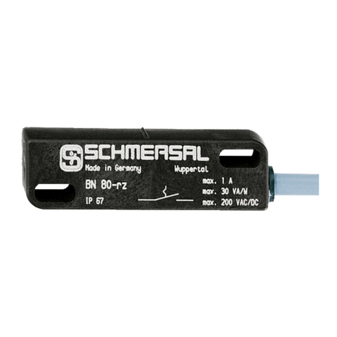
The magnetic reed switch can be used for monitoring the position of
movable guards and flaps in explosion-endangered areas of Zone 2
and 22 category 3GD. Installation and maintenance requirements to the
standard series EN 60079 must be met.
Actuation of the magnetic reed switch is only possible with the actuators
listed (see list in catalogue "Explosion Protection"). Faultless operation
and repeat accuracy is only assured with these actuators.
The user must evaluate and design the safety chain in
accordance with the relevant standards and the required
safety level.
Conditions for safe operation
Due to the specific impact energy, the components must be fitted
with a protection against mechanical stresses. The specific ambient
temperature range must be observed. The user must provide for a
protection against the permanent influence of UV rays.
2.4 Technical data
Equipment category:
L
II 3GD
Ex protection: Ex nC IIC T5 Gc X, Ex tc IIIC T90°C Dc X
Standards: EN 60079-0, EN 60079-15, EN 60079-31
Enclosure: AlSi 12 die-casting, painted
Max. impact energy: 4 J
Protection class: IP67 to IEC 60529
Connection: screw terminals
Cable section: max. 1.5 mm² (incl. conductor ferrules)
Cable entry: 2x M16
Operating principle: magnetic
Switching voltage: max. 250 VAC/DC
Switching current: max. 3 A
Switching capacity: max. 120 VA/W
Dielectric strength: > 600 VAC (50 Hz)
Actuating speed: max. 18 m/s
Switching frequency: max. 300/s
Switching time “Close”: 0.3 ms … 1.5 ms
Switching time “Open”: max. 0.5 ms
Bounce duration: 0.3 ms … 0.6 ms
Ambient temperature: – 15 °C … + 70 ºC
Storage temperature: – 25 °C … + 70 °C
Mechanical life: 108operations
Electrical life: 1 million … 1 billion operations, depending on load
Resistance to vibration: 50 g on sine wave oscillation
Switching point accuracy: ± 0.25 mm, T = constant
Resistance to shock: 30 g / 11 ms
Resistance to vibration: 10 … 55 Hz, amplitude 1 mm
Tightening force:
‒Cover screws: min. 0.6 Nm
‒Cable gland: min. 1.2 Nm
‒Blocking screws: min. 1.2 Nm
Cable glands:
L
II 2GD
Cable cross-section of the cable glands: min. Ø 6 mm;
max. Ø 10 mm
3. Mounting
3.1 General mounting instructions
Fitting is only authorised in a de-energised condition
• Any mounting position, provided that the active surfaces are opposite.
• Do not use the magnetic reed switch as limit stop.
• Two elongated holes are available for fastening the enclosure.
• Ensure the magnetic reed switch is mounted on a flat surface to avoid
tensile stresses that could damage the sensor or lead to varying
switching distances.
• Do not install magnetic reed switches and actuators in strong
magnetic fields.
• If possible do not install the magnetic reed switch and actuator on
ferromagnetic material.
• Do not expose the magnetic reed switch and actuator to strong
vibrations or heavy shocks.
• Inseparably fix the magnetic reed switch and actuator to the safety
guard.
• The use of a protective ground wire is imperative.
• Keep away from metal chips.
Please observe the recommendations regarding maximum
impact energy, actuating speed and tightening torque in the
technical data.
Any changes and alterations that limit the explosion
protection are not allowed.
Please observe the relevant requirements of the standards
ISO 12100, EN 953 and ISO 14119.
3.2 Dimensions
All measurements in mm.
6,5
60
75
30
22 104
M 16x1,5
M 16x1,5
7,5
6,5
10
9,5
25
11,5
47
52
