4
2Foryoursafety
These installation instructions should be read carefully prior to installation in order to
avoid potential danger and/or damage.
When installing the MONORAIL and AMS systems, the general safety instructions,
warning notes, and installation notes in these instructions should be followed as
precisely as possible.
Please do not hesitate to contact SCHNEEBERGER should you require any further
information.
2.1 Authorisedpersonnel
The MONORAIL and AMS systems should be installed by appropriately qualified or
trained specialists, e.g. by installers who have read and understood these instructions.
2.2 Intendeduse
MONORAIL and AMS are components for precise linear movement and distance
measurement.
MONORAIL and AMS must only be operated within the intended temperature ranges
(MONORAIL -40°C to +80°C, AMS 0°C to +70°C).
SCHNEEBERGER profiled linear guideways must not be used as safety components.
2.3 Generalsafetyandprotectivemeasures
SCHNEEBERGER assumes no liability for damage arising from the following:
• Improper handling, installation, and/or maintenance
• Improper use of the guideways and/or distance measuring system
• Arbitrary modifications to MONORAIL and AMS
In extreme cases – for example, in the event of the loss of rolling elements – carriages
may become separated from the rail. It should be checked prior to each use whether
a risk of personal injury exists in this case and any such risk excluded using suitable
design measures.
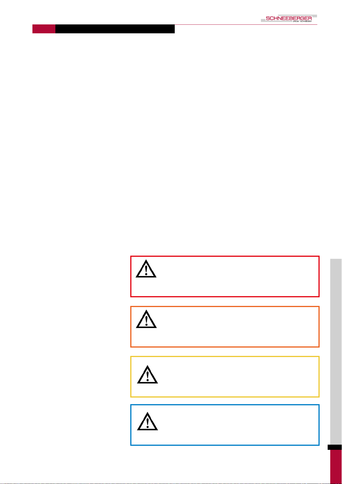
DANGER!
Danger to life posed by falling carriages!
Carriages may become separated from the guide rail and fall in the
event of overloading or the loss or rolling elements.
• All maintenance and conversion procedures on parts subject
to wear must be carried out in a load-free state.
• Additional fall protection must be applied.
• Design measures must be implemented to prevent individuals from
accessing the movement zones of the axis slides.
• MONORAIL and AMS are used in conjunction with heavy loads that may only
be lifted, installed and transported using a suitable lifting device together with an
adequate number of personnel.
• MONORAIL and AMS must be stored in their original packaging prior to installation
and protected from moisture and damage.
• MONORAIL AMS must be protected from magnetic fields. These could destroy
the magnetic measuring scale in the event of direct contact.
• Disconnect the power supply prior to any work on electrical equipment.
• Only use original SCHNEEBERGER parts for repair work.
• Comply with all country-specific regulations, standards, and guidelines for accident
prevention.