Schneider Kreuznach PC-TS SUPER-ANGULON 2.8/50 HM User manual

Jos. Schneider Optische Werke GmbH is certified ISO 9001. | We accept no responsibility for any errors and reserve 1
the right of modification without further notice. 2011/05 - 1069035 | © Jos. Schneider Optische Werke GmbH
Schneider Kreuznach PC Tilt/Shift Lenses
User Manual
PC-TS SUPER-ANGULON 2.8/50 HM
PC-TS MAKRO-SYMMAR 4.5/90 HM
with interchangeable bayonet mount for Canon EOS, Nikon, Pentax K or Sony Alpha
PC-TS APO-DIGITAR 5.6/120 HM Aspheric
with bayonet mount for Mamiya/Phase-One System
www.schneiderkreuznach.com
PC-TS Anleitung 2011.indd 1 25.05.11 20:45

Jos. Schneider Optische Werke GmbH is certified ISO 9001. | We accept no responsibility for any errors and reserve 2
the right of modification without further notice. 2011/05 - 1069035 | © Jos. Schneider Optische Werke GmbH
C
ANO
N
-
E
O
S
Schneider Kreuznach PC Tilt/Shift Lenses
Congratulations! You have made the right choice.
You have purchased a PC-TS lens from Schneider-
Kreuznach because you want the best possible image
reproduction quality while having the option to correct
perspective and to enjoy greater depth of eld through
tilting according to Scheimpug’s principle.
Your new PC-TS lens (PC = perspective control; TS =
tilt & shift) allows both a parallel shift to reduce or even
completely eliminate converging lines or perspective
distortion (“keystone correction”) and a swinging or tilt-
ing of the lens according to Scheimpug’s rule in order
to better utilize depth of eld (DOF) without an increase
in diffraction from further stopping down the aperture
and reducing sharpness. Parallel shift and lens swing
or tilt can be carried out independently of one another
in any desired direction (vertically, horizontally or
obliquely) thanks to separate rotary mounts.
This also provides you with the advantages usually as-
sociated with adjustable technical cameras to a degree
sufcient for most applications with your single-lens re-
ex camera (simpler and faster). You no longer have to
spend a lot of time on the computer correcting the key-
stone effect, with the accompanying loss of sharpness
(see page 8); and thanks to the Scheimpug tilt, you no
longer have to stop down to achieve sufcient DOF
(see page 9). This manual will help you make optimum
use of the advantages of your new lens.
Name of parts
Bayonet for lens cap
Pre-set aperture setting ring
Aperture setting ring
Base plate with 1/4" and 3/8" thread mount
Focusing ring
Locking wing bolt for rotating tripod mount ring
Rotary lens shifting ring
Sliding releasing ring with angular scale for
setting the direction of the parallel shift
Rotary lens tilting ring
Sliding releasing ring with angular scale for
setting the direction of the lens tilt
Interchangeable camera-specic bayonet lens mount
The PC TS lenses 4.5/90 HM and 5.6/120 HM are built
exactly like the 2.5/50 HM shown above up to the tripod
mount ring. Only because of their longer focal length
are their focusing rings, aperture setting rings and pre-
set aperture setting rings positions slightly different.
Pre-set aperture:
Set the working aperture with the aperture setting ring.
Open the aperture with the blue pre-set aperture set-
ting ring for framing and focusing. Then stop down with
this blue ring before releasing the shutter.
PC-TS Anleitung 2011.indd 2 25.05.11 20:45

Jos. Schneider Optische Werke GmbH is certified ISO 9001. | We accept no responsibility for any errors and reserve 3
the right of modification without further notice. 2011/05 - 1069035 | © Jos. Schneider Optische Werke GmbH
8°
a
b
c
Extra-large image circle for shift and tilt
The image circle diameter of normal lenses is only
slightly larger than the diagonal of the taking format,
e.g. 44 mm with a full frame 35 mm format which has a
diagonal of 43.3 mm. It is thus ensured that there is no
vignetting (darkening) in the image corners.
However, the PC-TS lenses have a much larger image
circle of 79.2 mm (2.8/50 HM), 87.8 mm (4.5/90 mm
HM, both for the full frame 35 mm format) and 153 mm
(5.6/120 HM for formats up to 45 mm x 60 mm). This
gives you enough freedom for parallel shift and
Scheimpug swing or tilt up to the mechanical limit de-
ned by the aperture of the camera bayonet mount
even when parallel shift and swinging or tilting are car-
ried out in any direction simultaneously.
Conventional shift lenses for the 35 mm format with an
image circle diameter of usually approximately 58 mm
allow for vignetting free shift of 10.7 mm in landscape
mode, but only 8.4 mm in portrait mode. The PC-TS
35 mm lenses allow 12 mm in both orientations, that is
almost 50% more shift in the portrait mode which is
particularly important for tall objects like buildings.
As the full-scale drawing on the right shows, there are
still sufcient reserves for any additional lens swing or
tilt according to Scheimpug for better utilization of
DOF even with a diagonal shift of 12 mm (which would
only be possible by 7.3 mm with a lens of 58 mm image
circle diameter).
Angled shots of objects with vertical edges are no less
problematic with regard to converging lines than archi-
tectural shots typically associated with this type of pho-
tography. However, due to the much shorter taking dis-
tance for product shots, a much smaller DOF results
and makes it necessary to stop down even further
which results in unwanted diffraction blur. It is only pos-
sible to stop down less by using lens tilt according to
Scheimpug (see page 9). Because the lens has to be
tilted downward, the image circle moves upward, in the
opposite direction to the parallel shift to remedy the
converging lines. This reduces the total shift.
If, however, the upward parallel shift is combined with a
downward Scheimpug tilt for building shots, the up-
ward image circle displacements are summed. The
enormous image circles of all three PC-TS lenses are
equal to this task.
Max. 12 mm
Max.
12 mm
Max.
12 mm
M
i
n
i
m
u
m
i
m
a
g
e
c
i
r
c
l
e
4
4
m
m
S
t
a
n
d
a
r
d
s
h
if
t
l
e
n
s
i
m
a
g
e
c
ir
c
l
e
5
8
m
m
S
m
al
l
e
s
t
P
C
T
S
i
m
a
g
e
c
i
r
c
le
7
9
.2
m
m
R
e
s
e
r
v
e
f
o
r
a
d
d
i
ti
o
n
al
le
n
s
t
il
t
Drawing in actual size
for 35 mm full frame sensor format
The image circle of all PC TS lenses is larger than neces-
sary for parallel shifts only. This is due to have a reserve
for additional lens tilts according to the Scheimpug rule.
When the lens is tilted down
the image circle moves up. The loss “a”
caused by the tilt will be compensated by the reserve (see
above); the gain “c” will be available when shifting down.
PC-TS Anleitung 2011.indd 3 25.05.11 20:45

Jos. Schneider Optische Werke GmbH is certified ISO 9001. | We accept no responsibility for any errors and reserve 4
the right of modification without further notice. 2011/05 - 1069035 | © Jos. Schneider Optische Werke GmbH
Schneider Kreuznach PC Tilt/Shift Lenses
PC-TS SUPER-ANGULON 2.8/50 HM
This lens has a standard focal length for a full frame
35 mm format and produces perspectives which ap-
pear very natural. It is therefore recommended mainly
for architectural photography as well as for town and
landscape imagery. It is also suitable for product shots
which require a much greater depth effect (greater spa-
tial perspective) than is possible with a longer focal
length lens otherwise preferred for this purpose. With
parallel shifting, buildings can be reproduced without
converging lines up to 100% higher (= twice as high)
above the horizon in landscape format or up to 67%
higher in portrait format than with lenses of the same
focal length without such a shift option.
PC-TS MAKRO-SYMMAR 4.5/90 HM
This lens with a focal length of 90 mm is the ideal solu-
tion for product shots with full frame 35 mm format. The
slightly longer focal length creates a longer taking dis-
tance for arranging the subject and provides extra
space for the lighting. The narrower angle of view
means that the backgrounds do not have to be so wide.
The sharpness is excellent throughout the focus range
to enable shots of very small objects (smallest format-
lling object eld 142 mm x 95 mm) with the long helical
mount; in addition, the Scheimpug tilt ensures a much
better DOF and the parallel shift provides more attrac-
tive product shots without converging lines or with
greatly reduced converging lines.
PC-TS APO-DIGITAR 5.6/120 HM ASPHERIC
This apochromatically corrected lens for the digital me-
dium format of the Mamiya/Phase-One system pro-
vides the adjustment possibilities of professional tech-
nical cameras. Depending on the digital back used (in
formats from 33 mm x 43 mm to 40 mm x 54 mm), the
focal length corresponds to the 35 mm equivalent of
98 mm to 80 mm. The PC-TS APO DIGITAR 5.6/120
HM is therefore ideal for product shots and satises the
highest demands thanks to its high resolution and ex-
ceptional image quality. The parallel shift and the
Scheimpug swing and tilt ensure a perfect perspective
and maximum DOF.
PC-TS Anleitung 2011.indd 4 25.05.11 20:45

Jos. Schneider Optische Werke GmbH is certified ISO 9001. | We accept no responsibility for any errors and reserve 5
the right of modification without further notice. 2011/05 - 1069035 | © Jos. Schneider Optische Werke GmbH
Specications
Effective focal length . . 51.75 mm
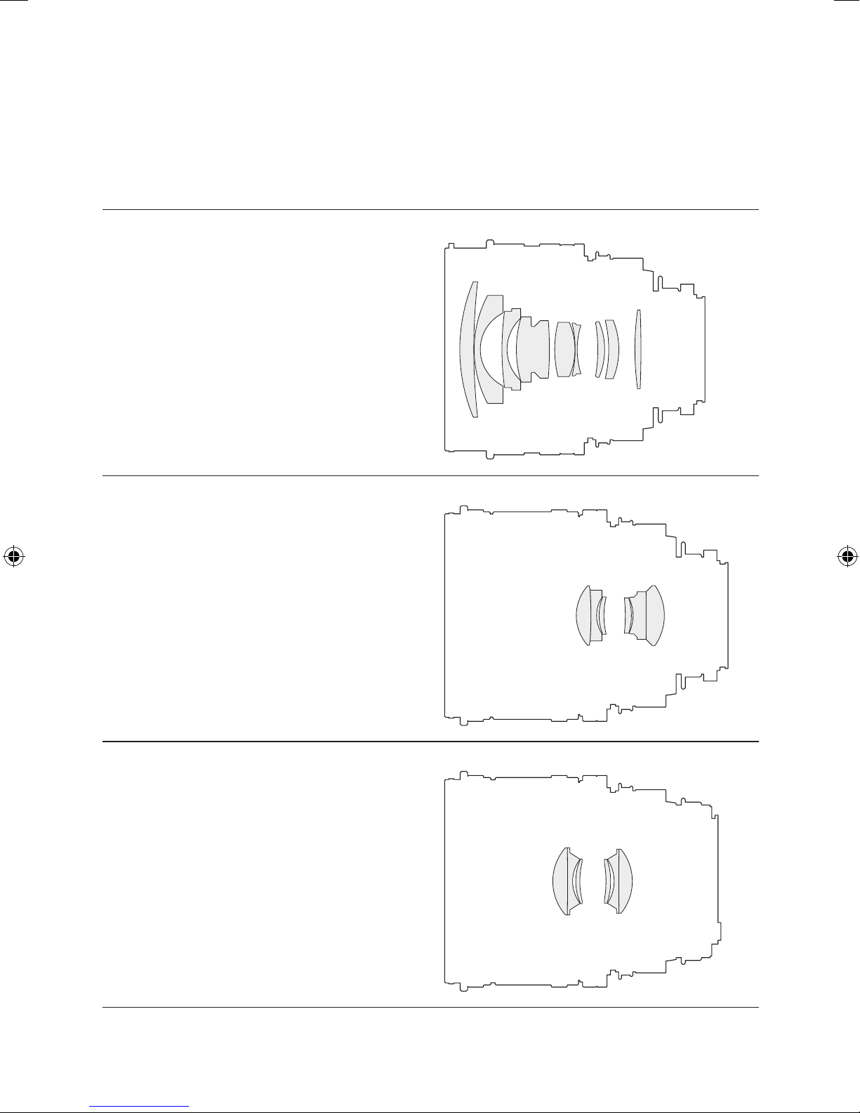
Optical design . . . . . . 9 elements in 9 groups
Coating . . . . . . . . . MC (multicoating)
Max. sensor format . . . 24 mm x 36 mm
Image circle diameter . . 79.2 mm (at innity)
Maximum shift reserve . 12 mm in every direction
Maximum tilt angle . . . 8° in every direction
Focusing . . . . . . . . manually
Nearest distance . . . . 0.65 m from sensor plane
Largest image scale . . 1:9.2 (w/o accessories)
Smallest subject size . . 220 mm x 330 mm
Aperture setting . . . . . manually, pre-set setting ring
Aperture setting range . 2.8 to 32 in 1/3 EV steps
Filter/accessory mount . M 95 x 1 and bayonet VIII
Lens shade . . . . . . . Accessory, threaded
Total length . . . . . . . 128.4 mm (EOS bayonet)
Maximum diameter . . . 108 mm (w/o tripod mount)
Weight . . . . . . . . . 1400 g
Tripod mount thread . . 3/8" and 1/4", 360° rotary
Available camera monts Canon EOS, Nikon,
Sony Alpha, Pentax K
Specications
Effective focal length . . 90.72 mm
Optical design . . . . . . 6 elements in 4 groups
Coating . . . . . . . . . MC (multicoating)
Max. sensor format . . . 24 mm x 36 mm
Image circle diameter . . 87.8 mm (at innity)
Maximum shift reserve . 12 mm in every direction
Maximum tilt angle . . . 8° in every direction
Focusing . . . . . . . . manually
Nearest distance . . . . 0.57 m from sensor plane
Largest image scale . . 1:4 (w/o accessories)
Smallest subject size . . 95 mm x 143 mm
Aperture setting . . . . . manually, pre-set setting ring
Aperture setting range . 4.5 to 32 in 1/3 EV steps
Filter/accessory mount . M 95 x 1 and bayonet VIII
Lens shade . . . . . . . Integrated (recessed lens)
Total length . . . . . . . 138.8 mm (EOS bayonet)
Maximum diameter . . . 108 mm (w/o tripod mount)
Weight . . . . . . . . . 1110 g
Tripod mount thread . . 3/8" and 1/4", 360° rotary
Available camera monts Canon EOS, Nikon,
Sony Alpha, Pentax K
Specications
Effective focal length . . 123.62 mm
Optical design . . . . . . 6 elements in 4 groups
Coating . . . . . . . . . MC (multicoating)
Max. sensor format . . . 45 mm x 60 mm
Image circle diameter . . 153 mm (at innity)
Maximum shift reserve . 12 mm in every direction
Maximum tilt angle . . . 8° in every direction
Focusing . . . . . . . . manually
Nearest distance . . . . 0.84 m from sensor plane
Largest image scale . . 1:5.3 (w/o accessories)
Smallest subject size . . depending in the digital back
Aperture setting . . . . . manually, pre-set setting ring
Aperture setting range . 5.6 to 32 in 1/3 EV steps
Filter/accessory mount . M 95 x 1 and bayonet VIII
Lens shade . . . . . . . Integrated (recessed lens)
Total length . . . . . . . 135.6 mm
Maximum diameter . . . 108 mm (w/o tripod mount)
Weight . . . . . . . . . 1110 g
Tripod mount thread . . 3/8" and 1/4", 360° rotary
Available camera mont . Mamiya / Phase One
Digital back P25+ . . . . 194 mm x 259 mm
Digital back P30+/P40+ 175 mm x 234 mm
Digital back P45+ . . . . 195 mm x 260 mm
Digital back P65+ . . . . 214 mm x 285 mm
➞
PC-TS Anleitung 2011.indd 5 25.05.11 20:45

Jos. Schneider Optische Werke GmbH is certified ISO 9001. | We accept no responsibility for any errors and reserve 6
the right of modification without further notice. 2011/05 - 1069035 | © Jos. Schneider Optische Werke GmbH
A B C D
180° 180°
0°0°
Shift max. 12 mm
180° 0° Shift max. 12 mm
0°
Schneider Kreuznach PC Tilt/Shift Lenses
Recommended base setting of swing/tilt and shift
This section explains how the lens swing or tilt and the
parallel lens shift should be set. Their purpose and ad-
vantages for improved image quality are described and
illustrated from page 8 onward.
The PC-TS lens should always be stored ready for use
in the base setting (untilted, without shift) to ensure
ease of use and to avoid errors. The sliding rings A (for
swing or tilt) and C (for shift) should be set, whenever
possible, to the angular values for the direction of
swing or tilt and shift which are most common in your
individual use. The angular value at the ring A for the
swing or tilt should always be set rst because the
whole lens is rotated in front of the ring A and any shift
direction set at the ring C (shift) would then change.
The direction of swing or tilt and shift is always the direc-
tion in which the angular value 0° faces on both rings.
Because the most frequent lens tilt is a downward tilt,
the sliding ring A should be set so that the angular
value 0° is at the bottom; the angular value 180° can
then be read at the top. To allow the sliding ring A to be
rotated, together with the whole front part of the lens,
this ring rst has to be pushed forward by around 1 mm
and held there. Grip the ring A with your thumb and
index nger, press it forward at its front bead and turn
the whole lens in the desired direction. The ring snaps
into the indicated 30° steps when released to prevent
any accidental change of the adjustment.
The parallel shift direction which is most common for
your purposes will depend on whether you usually
shoot subjects in a three-side view holding the camera
facing obliquely downward, such as products and
packaging for advertising (downward parallel shift) or
whether your shoot objects which project far above the
horizon, e.g. buildings and architecture (upward paral-
lel shift). Slide the ring C about 1 mm forward and at the
same time rotate the front part of the lens for downward
shift so that the angular value 0° is at the bottom (or
180° is at the top). For upward shift, in contrast, turn the
lens so that 0° is at the top. Ring C also snaps into the
displayed 30° steps when released.
If necessary, rotate the tripod collar after loosening the
locking bolt so that the base is at the bottom again.
In the standard conguration
the rings B and D must be turned to the left completely.
Before shifting down,
ring C must be turned with 0° down.
PC-TS Anleitung 2011.indd 6 25.05.11 20:45

Jos. Schneider Optische Werke GmbH is certified ISO 9001. | We accept no responsibility for any errors and reserve 7
the right of modification without further notice. 2011/05 - 1069035 | © Jos. Schneider Optische Werke GmbH
180° Shift max. 12 mm0° FE
0°
180° Tilt max. 8°
0°
E
Tilt the lens in the selected direction
If both a swing or tilt and a shift of the lens are required,
the swing or tilt direction must always be set rst at
the sliding ring A and only then the shift direction at ring
C. The actual tilt movement can be carried out later
before or after the shifting. The tilt always takes place
in the direction in which the angular value 0° on sliding
ring A faces.
If a downward tilt is required, the sliding ring A should
be pressed forward and the lens turned until the value
0° faces down. 180° can then be read at the top.
If the tilt should be to the left, because a surface or wall
running close to the camera at the left hand side needs
to be in sharp focus from the front to the rear, the lens
should be turned so that the value 0° on the sliding ring
A faces to the left; 270° will then face upward.
Once the tilt direction has been xed, the tilt angle, that
is the magnitude of the tilt, can be set at the rotating
ring B by turning it clockwise (viewed in the taking di-
rection). The value of the tilt angle can be read off at the
area E of the rotating ring B facing toward the camera
above the triangular mark (at 0° or at 180° from ring A).
The tilting of the lens always results in a displacement
of the plane of optimum sharpness of the subject and
therefore in a displacement of the DOF zone surround-
ing it. It is therefore always necessary to refocus after
tilting. The meter scale is not valid with a tilted lens.
See page 10 for a detailed explanation how to nd the
optimum tilt angle in practice.
Shift the lens in the selected direction
If the desired direction of the shift has been set e.g.
upward for very high buildings (0° at the top of ring C)
or downward for product shots in a three-side view (0°
at the bottom of ring C), as described on the left, the
required amount of shift can be set by turning the ring
D clockwise. The displacement path in millimeters can
be read off at the area F of ring D on the camera side.
The maximum shift is 12 mm in each direction.
When shifting with a tilted lens, the sharpness will
change so that it is always necessary to refocus.
After having set the direction
of the lens tilt with ring A (in this
picture with 0° downwards), the lens can be tilted up to 8°
in this direction by turning the ring B clockwise (seen from
the camera side). The tilt angle can be seen on the scale E.
By turning the ring D clockwise,
the lens can be shifted into the direction that has been se-
lected before (= in the direction of 0° on ring C, which is
upwards in this picture). If the lens has been shifted before
tilting the lens, the subject in the frame will be shifted a bit
by the lens tilt. Then it may be necessary to correct the
eld of view by a small additional shift; depending on the
focal length and the direction of the lens tilt, an increase or
a decrease of the lens shift may be necessary. However, in
every case after any tilt and any shift with a tilted lens, the
lens must nally be refocused precisely before shoting.
PC-TS Anleitung 2011.indd 7 25.05.11 20:46

Jos. Schneider Optische Werke GmbH is certified ISO 9001. | We accept no responsibility for any errors and reserve 8
the right of modification without further notice. 2011/05 - 1069035 | © Jos. Schneider Optische Werke GmbH
Schneider Kreuznach PC Tilt/Shift Lenses
When and why is shifting recommended?
If high buildings are photographed from a short dis-
tance away or if products and packagings are photo-
graphed from a three-side oblique view, the camera
normally has to be pointed upward or downward. The
sensor plane or lm plane is consequently not parallel
to the perpendicular edges of the subject. The subject
is therefore imaged as converging upwardly or down-
wardly like a trapezoid, which is commonly called “con-
verging lines”. The object height is furthermore repro-
duced in shortened form, that is not correct to scale.
This effect can only be avoided by using a lens with
such a large angle of view that the object is completely
captured without tilting the lens. So-called shift lenses
have such a large angle of view and can be shifted
upward, downward, and usually also sideward, relative
to the camera body so that the camera can be used
without tilting for shots obliquely upward, downward or
in any other direction.
While it is also possible to correct the irritating distor-
tion of converging lines by using image processing
software on a computer, this requires a much greater
amount of time than by shifting while photographing; it
also results in a substantial deterioration of image qual-
ity due to the “pixel spread” with subsequent vertical
and horizontal interpolation (resolution losses of way
over 50%), and with a parallel orientation of the con-
verging lines, the ratio of width to height changes so
that the subject appears vertically compressed or
stretched within the image. A vertical distortion correc-
tion is therefore required, with a further loss of sharp-
ness due to repeated pixel spread and interpolation in
which it is difcult to restore the correct proportions of
width to height (the mathematical calculation is very
complicated, the procedure is very time-intensive).
This is why adjustable technical cameras are preferred
for architecture, industry and product photography be-
cause they allow for a correct lens shift to eliminate or
attenuate converging lines and to maintain the propor-
tion of width to height. The new Schneider-Kreuznach
PC-TS lenses give you the benets of this shifting with
an SLR camera without any post-processing in correct
to-scale proportions and without losses in re solution
due to pixel spread and interpolation.
Horizon
Optical axis
Building not to scale but
vertically compressed
Converging lines
about 13°
Converging lines
… rectified with the help of a computer
Too wide Narrow
Original photo
Horizon
Optical axis shifted 9 mm
Building precisely to scale
and not cropped
Vertical lines are
parallel
Horizon
Too much
foreground
Optical axis
Building precisely to scale,
but its top is cropped
PC-TS Anleitung 2011.indd 8 25.05.11 20:46

Jos. Schneider Optische Werke GmbH is certified ISO 9001. | We accept no responsibility for any errors and reserve 9
the right of modification without further notice. 2011/05 - 1069035 | © Jos. Schneider Optische Werke GmbH
Greater depth of eld through lens tilt
Most subjects are three-dimensional and of varying
depth. A perfectly sharp image is, however, only possi-
ble for a lens at a distance xed by focusing on a planar
sensor if the object is likewise planar. All details in front
or behind this become more and more blurred with in-
creasing distance from this sharpness plane – even
more so the further the lens aperture is opened.
It is therefore normally necessary to stop down by sev-
eral f/stops for a sufcient depth of eld. Unfortunately,
the diffraction also increases in an amount critical for
high-resolution sensors; this is usually noticeable in full
frame 35 mm format from about f/8 or f/11 and in the
digital medium format from around f/11 or f/16.
However, lens tilt according to Scheimpug is a proven
way of increasing depth of eld while at the same time
reducing the required stopping down. The secret of this
technique is not a bypassing of physical laws (which is
naturally not possible), but rather the tilting of the DOF
zone at right angles to the optical axis (top gure) so
that the spatial extent of the subject is adapted better
(bottom gure).
For this purpose, the lens is tilted by an angle a such
that the image-side principal plane p of the lens (which
can be thought of as the aperture plane in simplied
terms) extends through the line of intersection S which
is formed by the image plane i and the Scheimpug
sharpness plane s shown in red.
The DOF zone included by two parallel planes with a
non-tilted lens becomes a DOF wedge with the edge E
in front of the line of intersection S on this tilting. The
opening angle of this wedge increases almost sym-
metrically as stopping down increases.
4
5
.
6
8
1
1
1
6
S
s
By tilting the lens according to the Scheimpflug rule,
the plane of best sharpness s (red line) can better
be adjusted to the course of the subject;
then f-stop 11 provides sufficient
depth of field
i p
E
4
5.6
8
11
16
3 m 100 m
For depth of field from
very near to very far
intense stopping down
is needed, e.g. to f/16;
the red line indicates
the plane of best
sharpness
5.83 m
f/stop
PC-TS Anleitung 2011.indd 9 25.05.11 20:46

Jos. Schneider Optische Werke GmbH is certified ISO 9001. | We accept no responsibility for any errors and reserve 10
the right of modification without further notice. 2011/05 - 1069035 | © Jos. Schneider Optische Werke GmbH
Schneider Kreuznach PC Tilt/Shift Lenses
How to nd the Scheimpug tilt angle
We want to tilt the lens so that the resulting slim depth
of eld wedge (yellow area in the gure on the right)
includes all subject zones to be imaged as sharp. Be-
fore we determine the required tilt angle, we rst have
to nd the optimum position of the Scheimpug plane s
within the subject as follows:
The subject zone being imaged has to be packed into
a wedge between two planes which is as small as pos-
sible as in the second gure between the bottom board
and a board (imagined to be weightless) placed directly
onto the subject. This board would lie on the highest
object in the foreground X and on the apparently high-
est object of the background Y from the perspective of
the foreground (as seen from the eye symbol in the
gure on the right and not from the camera). These two
objects X and Y have to be found in the subjec to be
imaged as sharp.
If we now connect the point A at half the height of the
highest (small) object X in the foreground to point B at
half the height of the apparently highest object Y in the
background, we have found the course of the ideal
Scheimpug plane for our subject. It is these two points
A and B which therefore have to be imaged as sharp
after the tilting of the lens with an open aperture.
A
B
Imaginary board
How to find the Scheimpflug plane
(plane of best sharpness)
X
Y
S
s
4
5.6
8
11
B
A
Shift
Tilt
N
F
With a tilted lens, the
wedge of depth of field rises
when focused to a shorter distance
and falls when focused to a
farther distance
Far
Near
E
i p
Scheimpflug rule: When the lens is tilted,
the image plane i,
the (image) principal plane p which is close to the aperture
plane in most cases and the Scheimpug plane (= plane of
best sharpness) s intersect in a common line S. The depth
of eld is an almost symmetrical wedge
relative to plane S.
To nd the optimum Scheimpug plane (plane of optimum
sharpness), look for the highest point X in the foreground
and then – seen from this point – look for the apparently
highest point Y in the background. If you imagine a board,
that loosely lies on the subject, it touches the subject in X
and Y. Then you will get two Scheimpug focusing points
A at the half height of X and B on the half height of Y. The
Scheimpug plane runs along a line through A and B.
S
s
i p
E
Scheimpflug principle
Barely sharp
D
e
p
t
h
o
f
f
i
e
l
d
Not sharp
Barely sharp
Very sharp
Barely sharpBarely sharp
Not sharp
PC-TS Anleitung 2011.indd 10 25.05.11 20:46

Jos. Schneider Optische Werke GmbH is certified ISO 9001. | We accept no responsibility for any errors and reserve 11
the right of modification without further notice. 2011/05 - 1069035 | © Jos. Schneider Optische Werke GmbH
1. First x the pivot direction. For this purpose, press
the rear sliding ring (A on page 6) forward and turn the
lens so that the angular value 0° faces the foreground
of the subject. This will be downward* in most cases.
2. If you want to correct converging lines by shifting, set
the front sliding ring (C on page 6) for a shift direction
upward so that the angular value 0° is at the top, for a
shift direction downward so that it is at the bottom.
3. Now align the camera with the tripod head so that
the sensor plane, and thus also the screen of the LCD
monitor is perpendicular.
4. Shift the lens (turn the ring D on page 6) until you
have the desired picture section. If the shift distance of
12 mm is not enough, use the tripod head to tilt the
camera a little more until the picture section is correct;
the “residual perspective” resulting from this is almost
always esthetically pleasing (see page 12).
5. Roughly focus on the foreground and tilt the lens by
rotating the rearmost rotating ring (B on page 6) to
2° on the PC-TS SUPER-ANGULON 2.8/50 HM
3° on the PC-TS MAKRO-SYMMAR 4.5/90 HM
4° on the
PC-TS APO-DIGITAR 5.6/120 HM ASPHERI
C
6. Focus on point A at half the height of the highest
object in the foreground (since the sharpness is always
displaced on tilting, you have to refocus after every tilt).
7. Check the sharpness at point B at half the height
of the apparently highest object in the background. If
this point is already absolutely in focus, you are n-
ished and can continue with step 10.
8. If, however, the apparently highest object H in the
background is sharper above point B, the tilt angle
was still too small. Then, you have to increase the tilt
angle a little, e.g. by 1° to 2° (depending on how close
the best sharpness is to point B) and return to the
above step 6.
9. If, however, the apparently highest object H in the
background is sharper below point B, the tilt angle
was already too high. Then, you have to reduce the tilt
angle a little, e.g. by 1° or even less (if the point of best
sharpness is already very close to the point B) and
again have to return to the above step 6 here.
You will then have nished the Scheimpug tilt after
running through the steps 6 - 7 - 8 or 6 - 7 - 9 (focusing
on A, checking at B, correcting the tilt angle) two or
three times.
10. You now only have to stop down to the correct
f/number for the required depth of eld. You can nd
this by taking test shots in which you check the critical
image details N and F (see gure at the bottom left) on
the LCD of the camera or via a connected computer.
11. Point N lies on the (near) border of the depth of eld
wedge at the camera side and is its most blurred point
there. Point F, as the point furthest away, is the most
blurred point at the border remote from the camera.
The blur is of equal magnitude at both points. Since we
want both points to be “sharp”, we have to stop down
so far that both appear sharp.
Take a test shot at aperture 8, for example. If N and F
are still not sharp at high enlargement, stop down fur-
ther and check the sharpness again. Repeat until N
and F are sharp enough for your application.
Since memory is no longer expensive, you can alterna-
tively take several shots after one another, e.g. at f/8,
f/11, f/16 and f/22 and then (later when you are back at
home) take the time you need on a large computer
monitor to select that shot in which N and F have the
required sharpness at the widest aperture.
At the end of this process, you will have to stop down
less, and thus have less diffraction blur, than would be
necessary without a Scheimpug tilt. You also have the
further advantage of a shorter exposure time under
available light or less need of ash energy (less expen-
sive ash unit) for ash shots in the photo studio.
* At rst glance, it may appear self-explanatory that the
foreground always has to be at the bottom. However, if
a lateral Scheimpug swing is carried out e.g. to relo-
cate the sharpness plane to an obliquel house front,
the foreground is at the left or right. If e.g. a ceiling
fresco is taken obliquely from below and the sharpness
is placed in the ceiling, the foreground is at the top.
PC-TS Anleitung 2011.indd 11 25.05.11 20:46

Jos. Schneider Optische Werke GmbH is certified ISO 9001. | We accept no responsibility for any errors and reserve 12
the right of modification without further notice. 2011/05 - 1069035 | © Jos. Schneider Optische Werke GmbH
Schneider Kreuznach PC Tilt/Shift Lenses
Converging verticals
without lens shift
Total correction
of distortion
25% residual
distortion
What is residual perspective and how do I get it?
If the camera only has a small upward or downward tilt,
any converging lines will also be slight. It is, however,
still possible to improve the esthetics of an image by
correcting the distortion using a shift of an adjustable
technical camera or of a shift lens. The steeper the tilt,
the more irritating the converging lines and the more
important the correction.
If, however, with a very steep upward or downward
view, the converging lines are aligned exactly vertically,
a tall building will look as if it is becoming wider toward
the top. We expect that a very high object becomes
smaller at the top where it is further away. It is therefore
meaningful not to align converging lines completely
parallel, but to leave a slight slant as a “residual per-
spective” in order to maintain a natural appearance.
Test shots with different amounts of keystone correc-
tion have shown that a correction of 70% to 80 %, or a
residual perspective of 30% to 20%, produces the
most natural impression depending on the subject.
This leads us to the following recommendation:
You can correct the keystone effect completely by shift-
ing up to around 5 mm in 35 mm format or up to around
8 mm with the larger sensor format of the Mamiya/
Phase-One system. If a greater shift is required for a
full correction, you should check whether the image
might not look better with some residual perspective. It
may be a good idea to prepare one completely cor-
rected shot and one with around 25% residual per-
spective to allow you to make a later decision on which
of the two images is better for your purpose.
You may ask: How do I set 25 % residual perspective?
First perform a full correction with an exactly perpen-
dicular sensor or LCD monitor of the camera. Read off
the amount of shift on the scale (F in the bottom gure
on page 7), e.g. 8 mm. Then reduce the shift by 25%
(this value is half of a half and is so particularly easy to
calculate); in our example, this is by 2 mm to only 6
mm. However, this does not give you any residual per-
spective, only the wrong image section. So you now
have to tilt the camera precisely by such a small angle
that you have the same image section again as previ-
ously with the complete parallel shift of 8 mm. This
small tilt gives you the very weak converging lines –
enough for a natural effect, but not with so much slant
that it looks unnatural.
PC-TS Anleitung 2011.indd 12 25.05.11 20:46
Other manuals for PC-TS SUPER-ANGULON 2.8/50 HM
1
This manual suits for next models
2
Table of contents
Other Schneider Kreuznach Lens manuals