Schneider Kreuznach Kino-Linear User manual

KINO-LINEAR™
USER MANUAL

Page 1
INSIDE THE BOX
The following items are included in the
Schneider Optics Kino-Linear™ packaging:
A. Kino-Linear™ Motorized Lens Mechanism
A1. Lens Holder
A2. Stage
B. Power Supply (12-volt output, 110-240 volt input)
C. Three Power Cord Types (US, UK, EU)
D. 12-Volt Trigger Cable (3.5mm Phono Type, Mono, 3M, Male-Male)
E. - Lens Retaining Ring
- Two Retaining Ring Screws (M3x6mm, Phillips head)
- Four Stage Lock Screws (M4x12)
- Four M4 T-Nuts (Extra)
Note: A Cine-Digitar Anamorphic lens is required to use
the Kino-Linear™ and must be purchased separately.
CONTENTS
Welcome ................................................................Page 1
Inside the Box ..........................................................Page 1
Attachment of Lens to Kino-Linear™ Mechanism ............... Page 2
Attachment of Kino-Linear™ to Chief® Ceiling Mount ........Page 3
Electrical Connections ................................................Page 4
RHP(Reverse Home Position) Units..................................Page 4
Adjusting the Anamorphic Image ....................................Page 5
Optional Kino-Linear™ Mounting Plate ............................Page 6
Use with JVC DLA-RS1&2 Projectors ..............................Page 6
About Schneider .......................................................Back Cover
Congratulations on your purchase of a Schneider Optics, Inc. Kino-Linear™anamorphic system. This system is composed of the finest optical
and mechanical components available. The Cine-Digitar Anamorphic lens is of commercial grade and should last indefinitely provided that it is
used within reasonable parameters of temperature and shock. The mechanical assemblies within the Kino-Linear™ lens mover are designed
for the demanding duty cycle of a professional screening room and have been tested to simulate in excess of 10 years use.
Installation by a qualified professional is recommended for best results.
WELCOME

ATTACHMENT OF LENS TO KINO-LINEAR™MECHANISM
Assembly Instructions:
1. Remove Kino-Linear™ mechanism and
Cine Digitar 1.33x anamorphic lens, if
purchased together, from packaging. Inspect
all components for damage that may have
occurred during shipping.
2. Place Kino-Linear™ base on table with
sliding stage facing up. Attach lens holder to
the stage using the four stage lock screws
provided. Note that the frame clamp needs to
be positioned toward the back of the Kino-
Linear™ base. See Illustration # 1.
3. Insert lens into the frame clamp of the
Kino-Linear™ as illustrated. The lens should
seat firmly into the clamp. Further loosen the
frame clamp lock screw if needed.
See Illustration # 1.
4. Insert the retaining ring into the frame clamp
and tighten the two retaining ring screws.
See Illustration #2.
5. Align the lens, rotating it until the flat sides of
the inner bezel are vertical. Tighten the frame
clamp screw. See Illustration #3.
6. Mount safety lanyard to projector mount
securely for safety.
Illustration #1 - Rear View of Kino-Linear™ with Lens Installed
Illustration #2 - Detail of Lens Retaining Ring
Illustration #3 - Front Detail
Page 2
Tools Required:
1. Screwdriver: No. 1 Phillips
2. Allen Wrench: 3mm, 3.5mm, 4mm, 1/16”, 5/32”

Illustration #8 - Chief PAN-2 Lens Support
Page 3
Accessories Needed:
1. Chief MFG, CMS Column, or 1.5” NPT pipe
of suitable Length. (Chief CMS™)
2. Chief MFG, RPA LCD/DLP Universal Ceiling
Mount. (Chief RPA™)
3. Chief MFG, SLBU/SLMU Universal Interface
Bracket, or custom interface bracket (not
shown) for your specific projector.
4. Chief MFG, PAN-2 Panamorph Lens Support.
(Chief PAN-2™)
5. Schneider Optics, Kino-Linear / PAN-2
Bracket (#54-018713).
Illustration #10 - Chief Mount
Assembly Instructions:
1. Install the Chief CMS™ Column and Chief
RPA™ Universal Ceiling Mount as instructed
in Chief manual.
2. Attach the Chief PAN-2™ lens support
to Chief RPA™ Universal Ceiling Mount as
instructed in Chief manual.
3. Replace the 90-degree adapter supplied
with the Chief PAN-2 lens support with the
Schneider PAN-2 bracket. See Illustration #7 & 9.
4. Mount projector interface bracket (universal/
custom) to the projector. Then place entire
assembly into the Chief RPA™ Universal
Ceiling Mount.
5. Attach the rear horizontal slot of the
Kino-Linear™ to the horizontal slots of the
adapter plate using the supplied “T-Nuts.”
See Illustration #11.Illustration #9 - Schneider Kino-Linear/PAN-2 Bracket
“RPA” and “PAN-2” are trademarks
of Chief Manufacturing.
Illustration #11 - Detail of Chief Mount
ATTACHMENT OF KINO-LINEAR™TO CHIEF®CEILING MOUNT

Page 4
ELECTRICAL CONNECTIONS
1. After the Kino-Linear™ unit is roughly aligned
with the projector, select the appropriate
power cord (US, UK, EU) for your location,
and connect the power supply to the unit and
electrical outlet. A solid green LED indicates
the unit is functional. See Illustration #5.
2. Connect trigger cable to the Kino-Linear™
unit from an appropriate source.
Note: A 12 volt trigger source will move lens
to the opposite side of slide.
See Illustration #4.
Note: The trigger connector polarity must be
positive (+) for plug tip and negative (-) for
plug body.
3. As an alternative trigger method, the Kino-
Linear™ can also be controlled via simple
contact closure without a 12-volt trigger. Use a
wire to connect terminal 1 to 2. This will move
lens to the opposite side of slide, similar to
using the 12-volt trigger.
4. To gain access to the terminal block, only the
motor cover needs to be removed. Unscrew
the six motor cover screws with 1/16” allen
wrench, and carefully pull back cover. See
Illustration #13.
Illustration #4 - Standard Lens Movement
Illustration #5 -Detail of Electrical Connection Area
1. The RHP unit allows installer to have the home position on the opposite
end of the slide in comparison to the standard Kino-Linear™ unit.
See Illustration #7.
2. The RHP unit can be identified by the engraving next to the serial number.
See Illustration #6.
RHP(REVERSE HOME POSITION) UNITS
Illustration #6 - RHP Unit Identification Illustration #7 - RHP Lens Movement

ADJUSTING THE ANAMORPHIC IMAGE
1. If focusing projector for the first time,
follow projector manufacture instructions
for setting up image.
2. <Important> Use the adjustments on the
Chief RPA™ Universal Ceiling Mount as mush
as possible to center image. Internal projector
image adjustments should be centered as
mush as possible for proper alignment to the
anamorphic.
3. Deploy the anamorphic lens into the projector
light path using the controller (Trigger ON),
checking to assure that no part of the lens or
cradle contacts any part of the projector. Move
lens away fro projector if needed by adjusting stage
lock screws. Observe image using the projector
test grid pattern.
4. If you see vertical “vignette” distortion on top
or bottom, adjust the height of the anamorphic
lens. Use the vertical/Yaw lock handle.
5. If you see left or right side “vignette”
distortion, adjust by repositioning the Kino-
Linear™on the Schneider PAN-2 bracket left
or right.
6. If you see “trapezoidal”, “barrel”, or “pin-
cushion” distortion, adjust the pitch lock handle
and the vertical/yaw lock handle.
7. If you see “parallelogram” distortion and
stretched corners, adjust lens rotation (roll).
See Illustration #12.
8. If the image requires focusing, loosen the lens
focus knob on the Schneider Anamorphic lens
to adjust.
Illustration #12 -Front Detail
Illustration #13 -Detail of Lens Adjustments
Page 5

Page 6
OPTIONAL KINO-LINEAR™MOUNTING PLATE
Illustration #14 - Projection Mounting Plate
1. This plate (#54-018714) replaces the
Chief MFG Pan 2 Panamorph Lens Support
and the Schneider Optics Kino-Linear / Pan
2 Bracket (#54-018713).
2. Attach the projector plate to the special
mounting holes (two places) on the projector.
The 90-degree lip should be pointing up
towards the ceiling . This plate is pre-drilled
to fit the following projectors: Sony VPL-
VW50, JVC DLA-HD10K, Panasonic PTAE-
10900U, and JVC DLA-RS1.
The plate can be drilled by the integrator to
fit additional projectors.
3. The locking “T-Nuts” should be oriented
forward to align with the slot on the rear
USE WITH JVC DLA-RS1&2 PROJECTORS
When using the Schneider Optics Kino-
Linear™ with the JVC DLA-RS1 or RS2
projectors, the standard bolts in the projector
feet may not be tall enough to avoid contact
between the Kino-Linear™ motor cover and
the surface.
To prevent any potential damage from this
contact, we recommend that you use the 50mm
replacement bolts provided with your mounting
plate to increase the clearance space.
Illustration #15 - Contact Problem with JVC DLA-RS1&2 Projectors
of the Kino-Linear™ lens mechanism. The
knurled gripping edge of the nuts should face
rearward. See Illustration 14.
4. The lens on the Kino-Linear™ will be in
the home position when power is supplied to
unit. Position the Kino-Linear™ in front of
the projector lens and align the “T-Nuts” on
the mounting plate with the slot on the Kino-
Linear™. Slide the Kino-Linear™ sideways
until the Schneider anamorphic lens is directly
in front of the projector lens. Tighten the “T-
Nuts” until the entire assembly is secure. See
Illustration #10.
5. If attaching a JVC DLA-RS1 or RS2 projector,
please refer to the supplemental instructions
below regarding the projector feet.

Schneider Optics, Inc.
7701 Haskell Avenue
Van Nuys, CA 91406
Phone: +1 818 766-3715 • +1 800 228-1254
Fax: 818 505-9865
Email: info@schneideroptics.com
www.schneideroptics.com
Jos. Schneider Optische Werke GmbH
Business Unit: Cinema
Ringstr. 132 • D-55543 Bad Kreuznach
Phone: ++49-(0)671-60 12 82
Fax: ++49-(0)671-60 11 08
Email: kino@schneiderkreuznach.com
www.schneiderkreuznach.com
9010-0050 Rev 1.31
ABOUT SCHNEIDER
Schneider Optics is the U.S. subsidiary
of the world-renowned German optical
manufacturer, Schneider-Kreuznach. Schneider
has been producing the highest quality optics
on the market for over 90 years, offering
solutions for large-format photography, photo
enlarging, motion picture projection, optical
filtration, and industrial applications. In 2000,
Schneider Optics acquired Century Precision
Optics, adding its over 50 years experience
manufacturing superior attachments for film
and video.
Schneider Optics has offices in Hauppauge, NY
and Van Nuys, CA and a network of hundreds
of dealers around the globe, ready to assist you
with any of your imaging needs.
Joseph Schneider founded the company in
1913 in Bad Kreuznach, Germany. Since that
time the Schneider factory has been constantly
modernized, always remaining state-of-the-art.
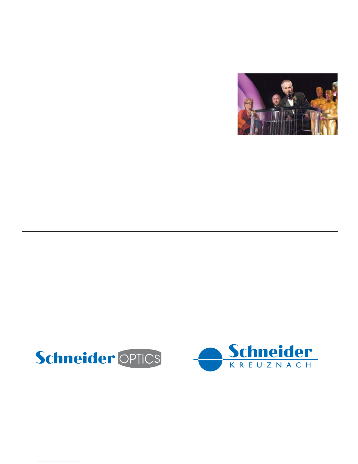
Schneider Cinema Projection Lens technology has
won four Technical Achievement Awards from the
Academy of Motion Picture Arts and Sciences
The factory is fully compliant with ISO 9001
standards. Its U.S. subsidiary, Schneider Optics,
was founded in 1972.
Century Optics first opened its doors
in North Hollywood, CA in 1948, and
quickly gained a reputation for expert lens
repair, custom modification and intelligent
innovation. In the early 80’s Century
began creating what has become the most
extensive array of ultra-high quality video
lens accessories available anywhere.
Separately the two companies were leaders
in their respective spheres of the optical
world—both having been awarded Technical
Achievement Awards from the Academy of
Motion Picture Arts and Sciences (Schneider
in 2005, 2001, 1978 and 1976; Century
in 1992). Together they are the ultimate
solution to all your optical needs.
Table of contents
Popular Projector Accessories manuals by other brands

Panasonic
Panasonic ET-ELW02 Lens Replacement and Installation Procedure

Sharp
Sharp XVZ-9000 Lamp unit operation manual

3M
3M Wireless Network Module EP8790NET Operator's guide

promethean
promethean ActivExpression 2 Startup guide

Navitar
Navitar NuView 489MCL1625 installation instructions

Future Automation
Future Automation PD3.5 installation instructions