manuals.online logo
Brands
  1. Home
  2. •
  3. Brands
  4. •
  5. SCHNERZINGER
  6. •
  7. Music Equipment
  8. •
  9. SCHNERZINGER GROUND PROTECTOR User manual

SCHNERZINGER GROUND PROTECTOR User manual

GROUND PROTECTOR
GROUND 2019-12 V1 en
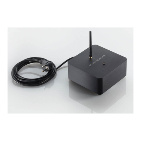
Picture similar
Package Contents
GROUND PROTECTOR
CONTROL UNIT (COUA)
12V Power Supply, cable length 1,5m
3,5mm jack extension cable 5m
Antenna
1 GROUND INTERFACE
1
Contents
PROTECTOR SYSTEM
GROUND PROTECTOR
Setting up a SCHNERZINGER system
Connecting the Hi-Fi Components
Setting up the GROUND PROTECTOR
Lasting effect of the GROUND PROTECTOR
Dear customer,
Thank you for your purchase of a SCHNERZINGER product.
Please take the time to precisely read the information in this guide. You
will find important instructions to use your product and hints for the
optimal integration into your Hi-Fi system.
This guide facilitates your use of the product, promotes understanding
its functional characteristics and helps you to obtain the full efficiency
of the product.
We hope you enjoy your new SCHNERZINGER product.
Please clean the product with a non-scratching dry duster only. Avoid
using cleaning agents.
A potting compound in the devices protects the innovative GIGAHERTZ
CANCELING technology with its particular electrical components
specially manufactured for SCHNERZINGER against direct access and
screening via X-ray or magnetic field applications. A slight rustling
caused by this potting compound is normal and does not result in any
functional impairment. There are no informed crystals in the devices.
In case of malfunctions contact your SCHNERZINGER dealer. Please do
not attempt to service the device yourself or to open it, in that case you
will lose your entitlement for our manufacturer warranty.
In the case of damages at the power plug or power cable please initiate
an exchange at SCHNERZINGER via your dealer.
PROTECTOR SYSTEM
The music reproduction quality of an audio system is highly affected by low and high frequency electrical interfering fields,
caused by Wi-Fi, cellular radio, power lines etc. With the PROTECTORS and their integrated trendsetting GIGAHERTZ
CANCELING technology, SCHNERZINGER has developed a product category that actively eliminates the sonic effects of low and
high frequency interfering fields.
The PROTECTORS significantly enhance the transmission quality of audio systems. The sonic effects include an astonishingly
higher spatial depth and resolution as well as increased broad and fine dynamics in music reproduction.
Utilizing the operating principle and efficiency of the GIGAHERTZ CANCELING technology, the SCHNERZINGER PROTECTORS
represent a unique solution in the market.
An important health aspect: protector technology does not increase radiation exposure within the room.
2
GROUND PROTECTOR
The GIGAHERTZ CANCELING technology of the GROUND PROTECTOR extremely effectively clears up grounding resp. ground
problems via its 3-channel-system.
•Channel 1 clears up grounding resp. ground problems of the attached devices
•Channel 2 directly operates in the signal path of the attached devices
•Channel 3 clears up interfering fields within the Hi-Fi system power distribution, without slowing down current flow at all.
Moreover the bidirectional operating device connections (GROUND INTERFACES) prevent transmission of interfering fields
between the Hi-Fi devices.
The operating principle and efficiency of the GROUND PROTECTOR are unique; a single GRID PROTECTOR raises the potential
of the entire music system to a new level.
Setting up a SCHNERZINGER system
Recommendation for the first setting resp. resetting of several SCHNERZINGER components:
1. Step:
Connect all components
- with the power circuit, if required (see manual)
- with the Hi-Fi devices (GROUND, GIGA GUARD, SPEAKER AMP)
2. Step:
Set all switches at all components to basic setting (switches to position 0).
3. Step:
Test each component one after the other for its optimal setting according to the manual, with the following configuration
sequence:
CABLES, GROUND PROTECTOR, GRID PROTECTOR, POWER GUARD, OPERATOR/NEW INNOVATOR, SPEAKER AMP PROTECTOR,
EMI PROTECTOR, GIGA PICCOLO PROTECTOR, GIGA GUARD, GIGA PROTECTOR
If you add your device to an already existing SCHNERZINGER chain, outstanding results will be obtained mostly when all
devices will keep their former settings and just the additional product will be installed and configured as described in its
manual.
If this does not provide satisfactory results, we recommend a complete system resetting.
3
Connecting the Hi-Fi Components
For each single component please test the optimal input; primary digital inputs,
alternatively analog inputs. Per component only one INTERFACE will be
connected. If the right and left channels are available for analog inputs, one
channel will be connected via an INTERFACE, while the second channel may be
connected to a GIGA GUARD. If no digital or analog input is available, the effect of
an INTERFACE may also be tested at an output (digital or analog, but no speaker
terminal*).
Connected this way, the GROUND PROTECTOR operates in the component
particularly effective, both via the signal path as well as via the grounding.
If a component to be connected has no suitable free input or output, the
connection can be done just via the grounding with the INTERFACE Option
Chassis Ground.
4
The GROUND PROTECTOR can be connected to up to 8 components (but no speakers*). Hi-Fi Components are connected by
INTERFACES, available in the grades** REFERENCE and EXTREME.
It’s recommended to connect all key components of the Hi-Fi system to the GROUND PROTECTOR, starting with the major source, the
other sources and further on in the direction of signal flow through the preamp to the power amplifier. The particular Hi-Fi component
should be switched off* during installation.
Via the INTERFACE options RCA, XLR/W, XLR/M, BNC, USB Type A and Type B first the free inputs of the Hi-Fi components are available to
connect to the GROUND PROTECTOR.
Caution –risk of damage
Choosing the quality level for a single interface not only affects the effect on the
connected component, but affects the GROUND PROTECTOR as a whole.
SCHNERZINGER Advisory Service will be glad to support you.
*
**
The GROUND PROTECTOR has three power levels and two functional circuits to simply adjust bandwidth and clock rate of GIGAHERTZ CANCELING technology via toggle
switches. This makes it possible to adapt to any interference field spectrum. The change in bandwidth extends or decreases the detection range, changing the clock rate
the processing speed.
The rule is: the narrower the bandwidth, the higher the efficiency - the smaller the detection range. The lower the clock rate, the higher the extinction rate - the less
interference frequencies are detected.
Changes need some time to take effect mostly. Therefore at each of the following steps you should wait for app. two minutes before judging.
Do not change the results as determined from the previous steps when you do the subsequent steps.
5
4. Step: Switch in front in position 0 - power level 1
Start with switch setting 0 = power level 1 –with CONTROL UNIT, without
12V power supply.
1. Step: Connecting to the power grid
The GROUND PROTECTOR should be connected* to the first slot of the Hi-
Fi power strip.
3. Step: Connecting the Hi-Fi Components
See separate page 4
Setting up the GROUND PROTECTOR
1. Step: Base setting
Usually (power level 1), the GROUND PROTECTOR will be operated without
the 12V power supply. To maintain its performance, it should be connected
to the grid with CONTROL UNIT and 12V power supply once a year for 15
minutes.
Connect antenna (upright position) and CONTROL UNIT (COUA) to the
GROUND PROTECTOR, without 12V power supply.
The other ports are reserved for PROFESSIONAL LINE accessories. The
optional GROUND PROTECTOR BOOSTER will be connected to one of the
ports A-D.
Set all 9 switches to base setting 0.
* note the correct phase (marked with a silver dot) –measure the phase of your socket.
6
5. Step: Switches left:
Functional circuit I –setting the bandwidth
Switches: L1 = narrow to L4 = wide
Starting from the base setting the switches L1 - L4 will be set sequentially from
position 0 to position 1. Each step will increase the bandwidth.
If the bandwidth is to low, the best possible effect will not be reached yet. If
the bandwidth is to high, even a sound degradation may occur.
The test ends, when the subsequent step won’t achieve a better result.
6. Step: Switches right:
Functional circuit II –setting the clocking
Switches: R1 = low to R4 = high
Starting from the base setting the switches R1 - R4 will be set sequentially
from position 0 to position 1. Each step will increase the clocking pace.
If the pace is to low, the best possible effect will not be reached yet. If the
pace is to high, even a sound degradation may occur.
The test ends, when the subsequent step won’t achieve a better result.
7. Step: Switch in front –adjustment of the power level:
If power level 1 is not sufficient for the present interference field spectrum,
2 additional power levels can be activated. This requires the permanent
connection of the 12V power supply* to the CONTROL UNIT and the grid.
The 12 Volt power supply should be connected to a power circuit separate
from the Hi-Fi system –ideally even to a different power phase.
Do not change the previously tested switch setting of the functional circuits
I and II!
Activate power levels 2 and 3 with the front switch. Check the result
compared to switch position 0 (without 12V power supply). If the result
improves with power level 2 or 3, it is recommended to repeat steps 5 and
6 with the best power level.
0 = Power Level 1 –with COUA, without 12V power supply
1 = Power Level 2 –with COUA, with 12V power supply, LEDs on
2 = Power Level 3 –with COUA, with 12V power supply, LEDs high
* note the correct phase (marked with a silver dot) –measure the phase of your socket.
Setting up the GROUND PROTECTOR
Lasting Effect of the GROUND PROTECTOR
The GROUND PROTECTOR constantly operates to clear up interfering fields effectively and comprehensively.
If after a while you once want to hear the performance of your system without your GROUND PROTECTOR, the buffering
effect absolutely has to be considered.
If the GROUND PROTECTOR is switched off for a short time only, it still takes effect because of the buffering of the power
supply unit.
Disconnect the 12V power supply (if connected) and the CONTROL UNIT from the power grid and the GROUND PROTECTOR
resp. and detach the power cable of the GROUND PROTECTOR from the power grid. Remove all other connections
completely, especially the INTERFACES. Additionally remove the antenna, place the unit on the floor and set the switch in
front to position 2. Keep these conditions for several hours, preferably overnight. This way you achieve that the GROUND
PROTECTOR has no effect any more.
Upon recommissioning the interfering fields will be cleared again fast.
Imprint
Schnerzinger UG (haftungsbeschränkt) & Co. KG
Klüsenerskamp 14 | 44225 Dortmund
Registergericht: Amtsgericht Dortmund | HRA 17290 | USt-IdNr.: DE276913602
Pers. haftende Gesellschafterin:
SCHNERZINGER Verwaltungs UG (haftungsbeschränkt)
Registergericht: Amtsgericht Dortmund | HRB 23752
Geschäftsführerin: Sandra Austerschulte
Phone +49 (231) 13 38 50 15 | [email protected]
7
Contact
sales@schnerzinger.com
Phone +49 (231) 13 38 50 15

Other SCHNERZINGER Music Equipment manuals

SCHNERZINGER MULTI GUARD User manual

SCHNERZINGER

SCHNERZINGER MULTI GUARD User manual

SCHNERZINGER GRID PROTECTOR User manual

SCHNERZINGER

SCHNERZINGER GRID PROTECTOR User manual

SCHNERZINGER MULTI GUARD User manual

SCHNERZINGER

SCHNERZINGER MULTI GUARD User manual

SCHNERZINGER GRID PROTECTOR User manual

SCHNERZINGER

SCHNERZINGER GRID PROTECTOR User manual

SCHNERZINGER SPEAKER AMP GUARD User manual

SCHNERZINGER

SCHNERZINGER SPEAKER AMP GUARD User manual

SCHNERZINGER ROOM GUARD User manual

SCHNERZINGER

SCHNERZINGER ROOM GUARD User manual

SCHNERZINGER GIGA GUARD User manual

SCHNERZINGER

SCHNERZINGER GIGA GUARD User manual

SCHNERZINGER GRID PROTECTOR User manual

SCHNERZINGER

SCHNERZINGER GRID PROTECTOR User manual

Popular Music Equipment manuals by other brands

McIntosh MX150 Connection diagram

McIntosh

McIntosh MX150 Connection diagram

Malekko QUAD ENVELOPE manual

Malekko

Malekko QUAD ENVELOPE manual

Industrial Music Electronics BIONIC LESTER MARK III Operation manual

Industrial Music Electronics

Industrial Music Electronics BIONIC LESTER MARK III Operation manual

Avid Technology Pro Tools Quartet quick start guide

Avid Technology

Avid Technology Pro Tools Quartet quick start guide

dbx 566 Brochure & specs

dbx

dbx 566 Brochure & specs

EMW DX700 Operation manual

EMW

EMW DX700 Operation manual

Technics SX-GN6 owner's manual

Technics

Technics SX-GN6 owner's manual

Roland S-0808 features and benefits

Roland

Roland S-0808 features and benefits

2hp LFO manual

2hp

2hp LFO manual

DAPAudio ZoneControl MKII Product guide

DAPAudio

DAPAudio ZoneControl MKII Product guide

DOEPFER PK88 quick start guide

DOEPFER

DOEPFER PK88 quick start guide

Samson GRAPHITE M32 quick start guide

Samson

Samson GRAPHITE M32 quick start guide

Furman SPB-8 owner's manual

Furman

Furman SPB-8 owner's manual

Vintage Revolution Acoustic box live1.0 rel A owner's manual

Vintage Revolution

Vintage Revolution Acoustic box live1.0 rel A owner's manual

Schatten Design CV Clip-On Violin Pickup instructions

Schatten Design

Schatten Design CV Clip-On Violin Pickup instructions

Alesis Studio 32 Reference manual

Alesis

Alesis Studio 32 Reference manual

Devialet Phantom user guide

Devialet

Devialet Phantom user guide

Roland S-1608 - ARCHITECTS AND ENGINEERS specification

Roland

Roland S-1608 - ARCHITECTS AND ENGINEERS specification

manuals.online logo
manuals.online logoBrands
  • About & Mission
  • Contact us
  • Privacy Policy
  • Terms and Conditions

Copyright 2025 Manuals.Online. All Rights Reserved.