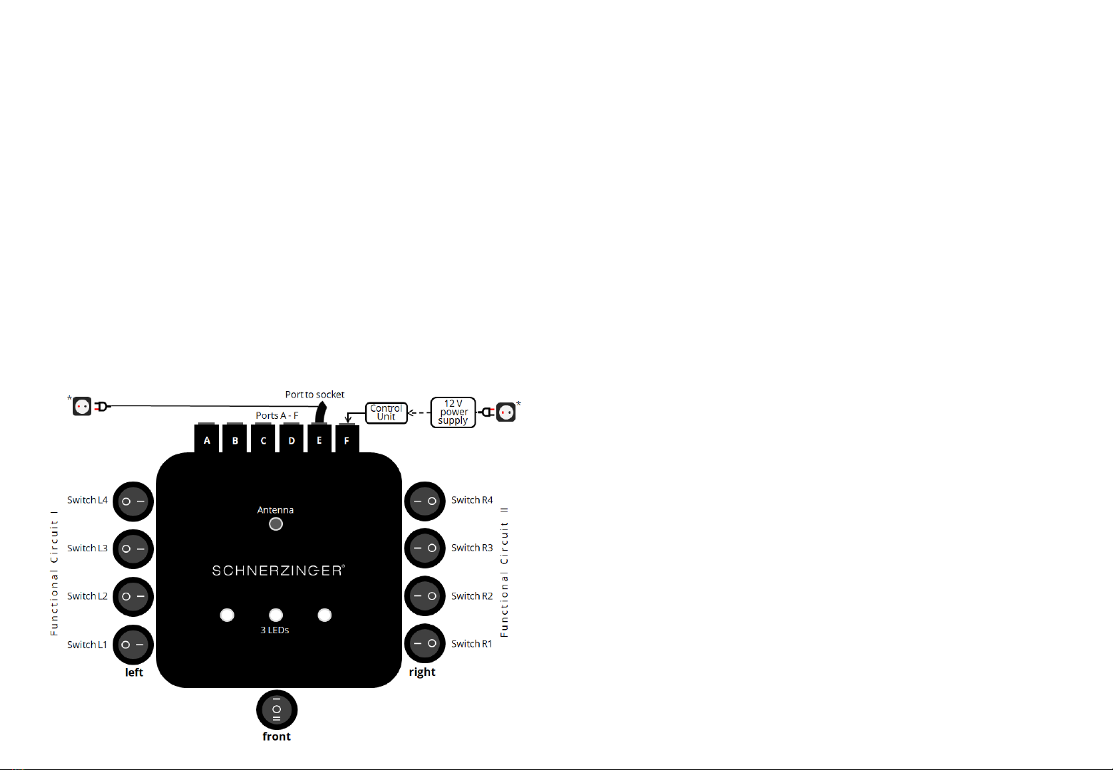
9
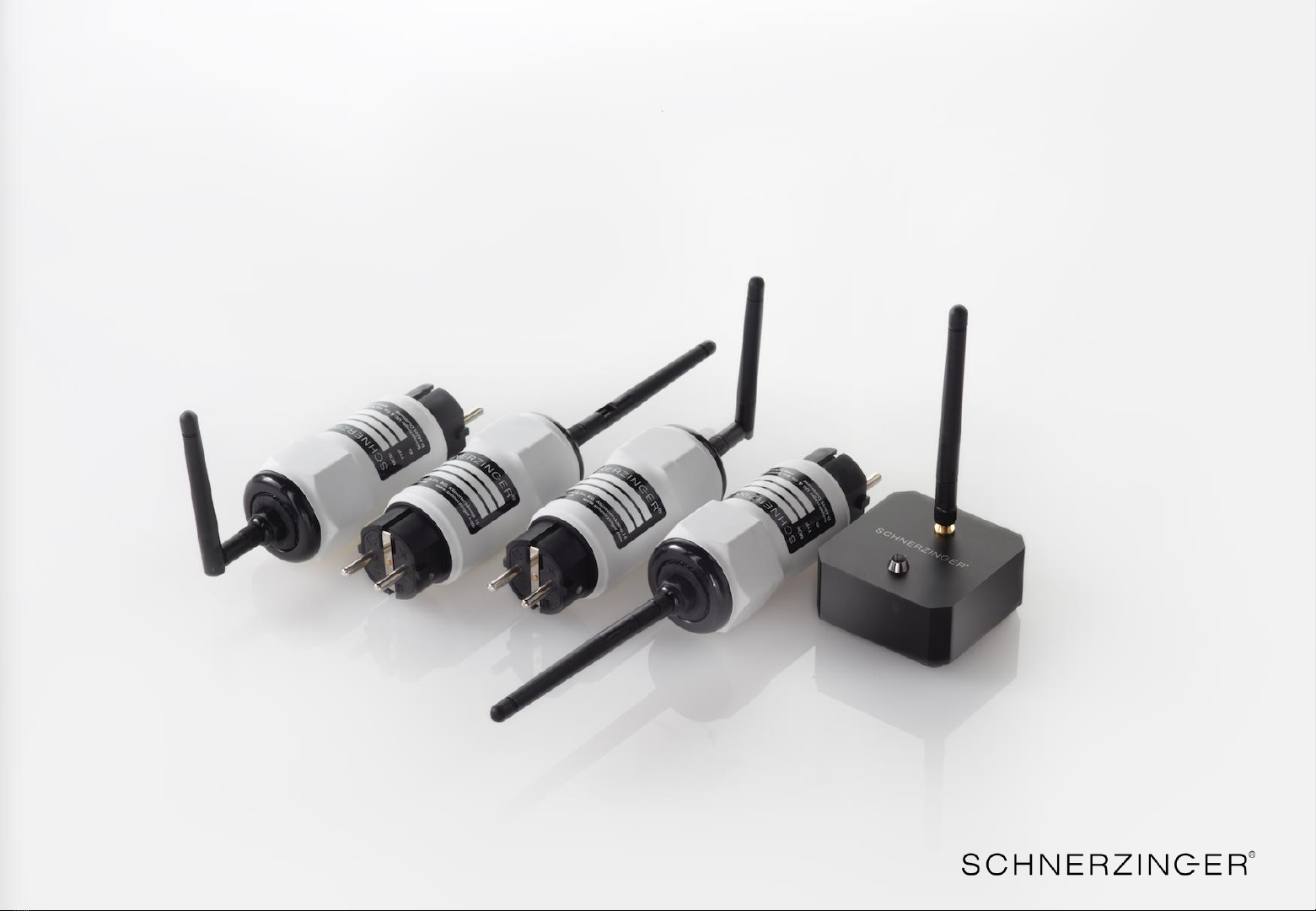
Setting up the MULTI GUARD
6. Step: GRID PROTECTOR switches left:
Functional circuit I –setting the bandwidth
Switches: L1 = narrow to L4 = wide
Starting from the base setting the switches L1 - L4 will be set sequentially
from position 0 to position 1. Each step will increase the bandwidth.
If the bandwidth is to low, the best possible effect will not be reached yet. If
the bandwidth is to high, even a sound degradation may occur.
The test ends, when the subsequent step won’t achieve a better result.
7. Step: GRID PROTECTOR switches right:
Functional circuit II –setting the clocking
Switches: R1 = low to R4 = high
Starting from the base setting the switches R1 - R4 will be set sequentially
from position 0 to position 1. Each step will increase the clocking pace.
If the pace is to low, the best possible effect will not be reached yet. If the
pace is to high, even a sound degradation may occur.
The test ends, when the subsequent step won’t achieve a better result.
8. Step: GRID PROTECTOR switch in front –power level:
If power level 1 is not sufficient for the present interference field spectrum,
2 additional power levels can be activated. This requires the permanent
connection of the 12V power supply* to the CONTROL UNIT and the grid.
The 12 Volt power supply should be connected to a power circuit separate
from the Hi-Fi system –ideally even to a different power phase.
Do not change the previously tested switch setting of the functional circuits
I and II!
Activate power levels 2 and 3 with the front switch. Check the result
compared to switch position 0 (without 12V power supply). If the result
improves with power level 2 or 3, it is recommended to repeat steps 4 and
5 with the best power level.
0 = Power Level 1 –with COUA, without 12V power supply
1 = Power Level 2 –with COUA, with 12V power supply, LEDs on
2 = Power Level 3 –with COUA, with 12V power supply, LEDs high
* note the correct phase (marked with a silver dot) –measure the phase of your socket.