Operating, Mounting and Maintenance Instructions
en
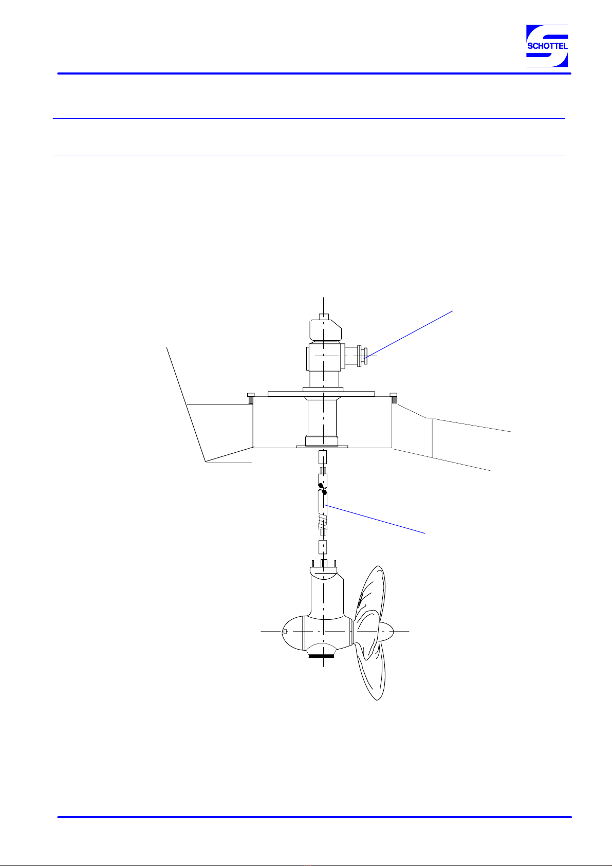
TDO--Ge
4/
8Safety and Enviromental Protection Regulation “SV 1” 3 348/98 1099236
Storage
The interior areas of the SCHOTTEL products in
question are preserved, following the trial run on the
test stand. Corrosion protection is sufficient for
approx. 6 months, when stored in dry environments
(no sea climate).
Prior to launching y prior to every intial start--up it is
necessary to top up oil
To this effect it is necessary to observe the different
operating instructions.
If a SCHOTTEL unit is put out of operation or re-
moved due to damage, then the unit must be filled
with fresh oil during the storage period, in order to
prevent damage through corrosion.
When storing in the open and/or with considerable
changes in ambient temperature, pressure relief
must be maintained for oil--filled units, as well as for
empty units (e.g new units).
This means:
In the case of units equipped with a vent valve,
the same be opened.
In case of units equipped with a mushroom--type
vent, pressure compensation is already main-
tained.
In the case of units which are only preas-
sembled, a provisional pressure compensation
device with dust protection must be installed at
a pipe connection.
ATTENTION
The storage of electric components, for instance in-
strument panels, switch cabinets etc. in the open is
prohibited.
3 Installation, Starting--up and Operation
Installation of SCHOTTEL Products
Before commencing installation, check that the
delivery is complete. All parts must be installed
and/or removed in a competent manner.
The installation of SCHOTTEL products requires
that:
Only those personnel who possess sufficient
technical expertise and the required equipment
shall be employed.
The installation proposals of SCHOTTEL--Werft
shall be observed, and/or requested as necess-
ary.
The relevant technical regulations shall be ob-
served.
Regulations of acceptance authorities under pri-
vate law and/or public law shall be complied
with.
Starting--up and operation (general)
The operating instructions of the relevant provisions
must be observed.
Before putting SCHOTTEL products into operation,
a check must be made for obvious defects and to en-
sure that all protection devices (e.g. cover plates) are
installed soundly. Defective units may not be put into
operation.
Units with defective instruments, pilot lamps and/or
control elements may not be put into operation.
The operator must make absolutely sure that no one
is located within the danger zone of the unit before
putting this into operation.
The indicating instruments must be checked for cor-
rect functioning directly after starting--up, if neces-
sary the unit must be switched off again.