Shockwave ICE Installation and operating instructions


2
TABLE OF CONTENTS
How To Get Help
Service Tips
Important Safety Information
Mounting Instructions
Fastener Torque
Understanding the Basics
Using Autotune System
Daily Operational Checks
Maintenance Schedule
General Troubleshooting
Troubleshooting –Autotune Overview
Autotune 1 Troubleshooting Electrical Diagram
Autotune 1 Troubleshooting Flow Diagram
Troubleshooting –Autotune
Troubleshooting –Finding an Air Leak
Troubleshooting –Fixing an Air Leak
Troubleshooting –Solenoid Orientation Check
Shock Configuration
Warranty
Warranty Claim Form
Warranty Claim Procedure
Service and Repair Procedure
3
3
4
5
6
7
8
9
10
11
12
13
14
15
16
17
18
19
20
21
22
23
TABLE OF CONTENTS

3
HOW TO GET HELP / SERVICE TIPS
ADDRESS
PHONE
FAX
EMAIL
HOURS
WEBSITE
2074 Henry Avenue, Sidney BC Canada, V8L 5Y1
+1.778.426.8544
+1.250.655.4334
8 AM to 5 PM Pacific Standard Time
shockwaveseats.com
SERVICE TIPS
HOW TO GET HELP
We are here to help. Call or email us if you have any problems, questions or concerns.
• Drawings and an Illustrated Parts Breakdown are supplied according to the specific ICE configuration ordered. Addi-
• Tell us what the concern is. Be sure to answer all the Who, What, When, Where and Whys of the situation so we have
a clear understanding and can provide the best advice.
• Please identify the SHOCKWAVE product by supplying the serial number, which is typically located inside the front
hatch on the helm side.
• Tell us who you are and what your relationship is with the product.
• Provide both wide angle and close-up photos of the item or area of concern.
• Let us know where you are located and your contact information.
• Tell us the urgency of the request.
• Refer to the Warranty Claim Procedure section of this document for more information.
4
IMPORTANT SAFETY INFORMATION
DANGER
Your SHOCKWAVE ICE will mitigate the effects of shock and vibration, reducing the potential of injury,
but it will NOT prevent the possibility of injury. The increased level of comfort and control provided by the
SHOCKWAVE ICE will allow for the operation of the craft at higher speeds in sea states which create high
shock loads on the craft and potentially the occupants; SHOCK LOADS THAT COULD POTENTIALLY EXCEED
THE ICE’S CAPABILITIES TO MITIGATE.
Operating marine craft in a high shock load environment is inherently hazardous. Tolerance to the effects of
shock and vibration vary from person to person and it is the responsibility of the craft operator to ensure the
safety of each person onboard. Pain and/or discomfort are indicators of a potential injury. Constantly monitor
the physical state of the craft and the personnel onboard. Hazardous operation of the craft may result in
serious injury, death or damage to the craft.
IMPORTANT
Follow IMPORTANT instructions located throughout the Operations and Service Manual to prolong the
appearance and service life of your SHOCKWAVE ICE Console.
WARNING
• Do not modify the equipment by drilling extra
holes, removing material, or adding extra
equipment. Serious injury can result.
• Do not use the ICE if it is, or appears to be,
damaged. Serious injury can result.
• Do not use seating if the seat to ICE attach-
ments are loose. Serious injury can result.
• Do not use the ICE if the resting height is
lower than normal. This may be an indication
of a damaged or leaking system. Serious injury
and damage can result.
• Do not operate the console with insufficient
air pressure in shocks to prevent bottoming.
Serious injury and damage can result.
CAUTION
• Do not use the ICE for uses other than its
intended purpose. Damage to the equipment
or bodily harm may result.
• Do not use the ICE if fasteners are loose.
Damage to the equipment or bodily harm may
result.
• Do not attempt to open, perform maintenance
or repair the ICE while the craft is underway.
Damage to the equipment or bodily harm may
result.
• Do not place items under or around the ICE
that may interfere with the ICE’s range of
motion. Damage to the equipment or bodily
harm may result.
IMPORTANT SAFETY INFORMATION

5
DANGER
Incorrectly installed ICE consoles can cause damage to the ICE and vessel, as well as cause serious injury or death.
WARNING
Control arms should be kept as short as possible. Do not extend more than 0.25” [6.35mm] per link end from
fully retracted position.
MOUNTING INSTRUCTIONS
• There must be enough deck structure to support the weight of the ICE and occupants within the vessel’s operational
• There must be no flex in the mounts or deck plate when the ICE is loaded.
• The shock brackets, linkage brackets, sway bar brackets and the ICE must not be modified.
• Do not mount the ICE on a curved deck if it was not specifically designed for the curved deck by SHOCKWAVE.
• Do not mount the ICE in the middle of an unsupported deck plate.
• Ensure that the movement of the ICE does not interfere with the vessel structure or equipment.
• Check operation of the ICE after installation by filling and draining the system. It must not bind or stick.
• All the ICE deck mounts must be positioned as per SHOCKWAVE specification. CAD files or a metal drill template for
• Ensure the ICE is true to the deck by using a plumb bob to find the center of the front and rear of the ICE and ensure
the ICE is aligned with the centerline of the mounts. Adjust the ICE by rotating the center shaft of the control arms
to extend or reduce the length.
C L
MOUNTING INSTRUCTIONS

6
RECOMMENDED FASTENER TORQUE
All fasteners are prone to becoming loose from sustained high-performance use. SHOCKWAVE recommends that
all bolts should be visually inspected for signs of being loose. Always use a thread-locker on fasteners to prevent
loosening. Please use the reference table below:
SIZE PITCH TORQUE (STAINLESS)
Dry
#6
M5
#8
M6
M8
M10
M12
5/16”
5/8”
3/8”
3/4”
7/16”
1”
#10
1/4”
1/2”
32
0.8
32
1.0
1.25
1.5
1.75
18
11
16
10
14
8
24
20
13
32
28
20
10 in-lbs
45 in-lbs
21 in-lbs
6 ft-lbs
15 ft-lbs
31 ft-lbs
54 ft-lbs
11 ft-lbs
96 ft-lbs
20 ft-lbs
131 ft-lbs
32 ft-lbs
299 ft-lbs
23 in-lbs
6 ft-lbs
45 ft-lbs
33 in-lbs
8 ft-lbs
47 ft-lbs
9 in-lbs
40 in-lbs
17 in-lbs
6 ft-lbs
14 ft-lbs
27 ft-lbs
48 ft-lbs
9 ft-lbs
82 ft-lbs
17 ft-lbs
111 ft-lbs
27 ft-lbs
254 ft-lbs
20 in-lbs
6 ft-lbs
38 ft-lbs
28 in-lbs
7 ft-lbs
40 ft-lbs
IMPERIAL
METRIC
Lubricated
RECOMMENDED FASTENER TORQUE

7
SHOCKWAVE ICE is designed to mitigate shock and
vibration encountered in high speed vessel operation on
rough seas. Following the suggestions in this section will
ensure that you are getting the most out of the product.
SET THE RIDE HEIGHT
The suspension must be allowed to compress and extend
as designed. Ensure the ICE is SET after each time the
payload on the ICE changes. This should allow the ICE to
sit 2” [50mm] less than full shock extension.
OPERATE IN THE VESSEL’S DESIGN ENVELOPE
Driving the boat beyond its limitations can have damaging
effects on the hull, engines and equipment. The SHOCK-
WAVE ICE is designed to provide shock mitigation to the
occupants. It will not protect the occupants from injury
caused from operating the vessel outside of its operational
envelope.
OPERATE THE VESSEL IN YOUR CREWS PHYSICAL
CONDITIONING ENVELOPE
Personal fitness is a limiting factor to the amount of sus-
tained G loads a person can endure without injury. If you
have inexperienced, relatively unfit or overweight per-
sons aboard, extra caution must be exercised to prevent
injury. The helmsman must be keenly aware of the shock
loads being transmitted to passengers not in the ICE or
standing, as serious injury can occur. Installation of the
SHOCKWAVE ICE provides an extra level of protection, but
the ICE will not protect a person from ALL shock loads.
OPERATE IN YOUR OWN ABILITY ENVELOPE
The SHOCKWAVE ICE will increase the confidence of
the helmsman. Overconfidence can lead to loss of boat
control. Generally, the ICE will permit greater control of
the vessel and the helmsman should focus on using the
control advantages of the shock mitigated ICE to better
look after the vessel and crew.
DO NOT TIE THE BOAT UP WITH THE ICE
As tempting as it may be, the SHOCKWAVE ICE is not
designed to tie up the boat.
ENSURE THAT THE ICE IS FUNCTIONING PROPERLY
Refer to the Caution Notes in the preceding sections.
The following is provided as a general checklist.
Do not operate the ICE if:
• The shock ride height is incorrect.
• Any components are loose, broken or missing.
• The ICE makes a strange noise when being operated.
USE SEAT BELTS – IF SUPPLIED
Seat belts prevent occupants from being ejected from the
vessel and the seat. When not in use, the seat belt buckle
clasp should be fastened to prevent damage to the ICE.
SET FORE AND AFT SEAT ADJUST CORRECTLY – IF
SUPPLIED
Correct ergonomics and posture enhance the ability to
operate the vessel safely and reduces the risk of shock
and vibration related injury. Take the time to adjust the
seat so that it is comfortable.
DO NOT SIT IN SEATS WITH HARD OR SHARP
OBJECTS. DO NOT WALK ON SEATS
Ensure that sharp objects and heavy gear are worn so that
they will not tear the upholstery.
RINSE ICE WITH FRESH WATER AFTER EACH USE
Rinse the ICE and the seats with fresh water after each
use, or every week if being stored outside, to prevent a
buildup of salt and debris.
COVER SEATS WHEN NOT IN USE
Seat covers are available from SHOCKWAVE to cover all
the seats.
TIE EVERYTHING DOWN
Pay attention to how you have stowed your gear. Elastic
shock cords and ratchet tie downs should be used to
secure all gear. Plastic containers of oil and other fluids
must be protected from chafing and puncture. Electronic
equipment must be secured to prevent damage from
shock loads.
CHECK ALL EQUIPMENT
Conventional mounting brackets for heavy items such as
fire extinguishers are subject to much more loading than
without shock mitigation. Make sure all your equipment
brackets are tight. Recheck major equipment bolts reg-
ularly. Wiring, cables and fluid hoses should be bundled
tightly and not allowed to flail. Do not allow any objects
under the ICE. The objects will limit the stroke of the ICE
and damage the objects or damage the ICE.
REMOVE OR PAD BODY STRIKE HAZARDS
Hard objects, particularly in the head strike zone, need to
be rounded and padded. When assessing your body strike
hazards consider a generous portion of clearance, as the
body will stretch in a high G situation.
UNDERSTANDING THE BASICS
UNDERSTANDING THE BASICS
8
The ICE is typically equipped with the SHOCKWAVE AUTOTUNE system that allows for simple filling and setting of the
ICE system. To get the most out of your ICE, it is important to always setup the suspension properly when weight is either
added or removed from the ICE.
STEP 1: Ensure the ICE is set up with its full occupants and gear weight in place.
STEP 2: If the red ‘WAIT’ light is illuminated the compressor is running to fill up the air tank. This can take up to 5
minutes. Once the green ‘READY TO FILL’ light is illuminated the air tank is full.
STEP 3: Lift and hold the momentary toggle switch in the ‘FILL’ position to fill all shocks. Hold the switch until the ICE is
at full height.
STEP 4: Set the ICE console to ‘SET’ height by holding the switch in the ‘SET’ position. This generally takes 5-10 seconds.
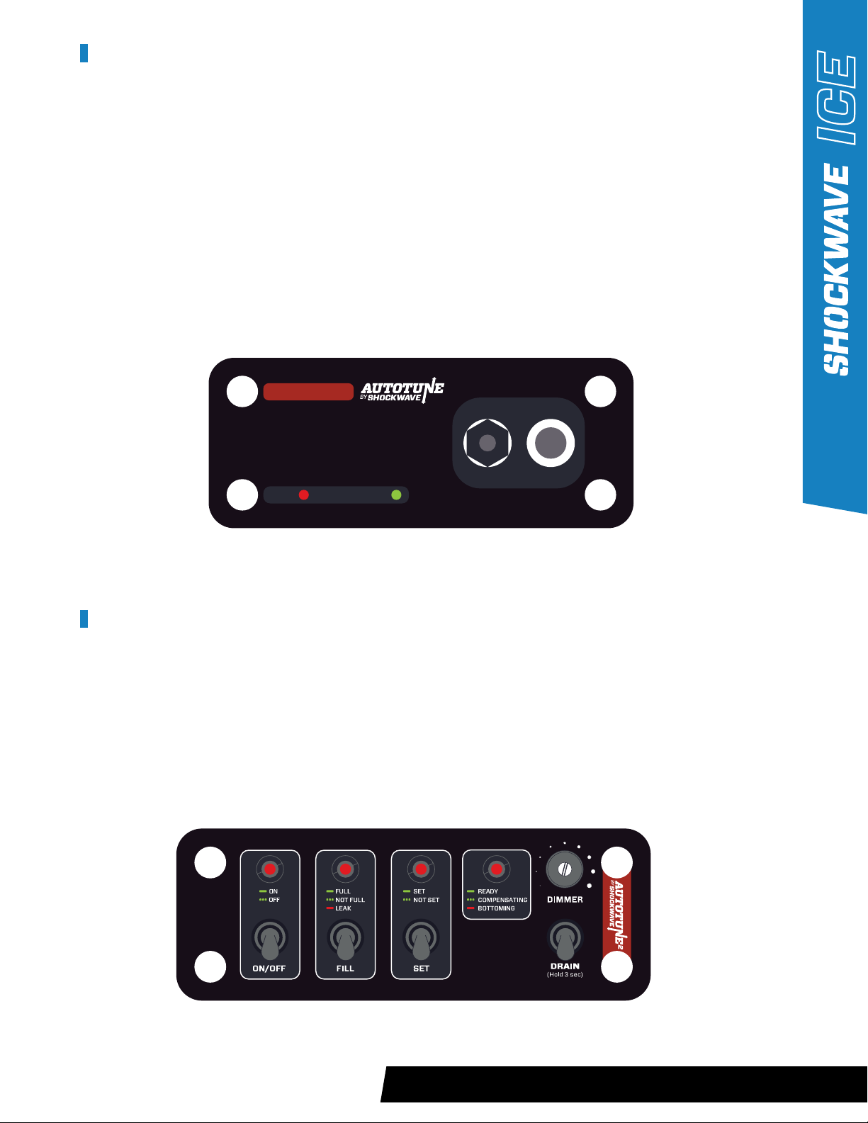
STEP 1: Ensure the ICE console is set up with its full occupants and gear weight.
STEP 2: Lift the ‘ON/OFF’ toggle switch to the up position. The ‘FILL’ light should be blinking.
STEP 3: Lift the ‘FILL’ toggle switch to the up position and wait until the ‘FILL’ light has stopped blinking.
STEP 4: When the system is ready, the ‘SET’ light will be flashing. At this time hold the ‘SET’ toggle down until the light
stops blinking. At this point the ‘STATUS’ light should be solid green in the “READY” state.
USING AUTOTUNE 1 SYSTEM
USING AUTOTUNE 2 SYSTEM
1LOAD OCCUPANTS AND GEAR INTO ICE
2WAIT UNTIL GREEN LED IS ILLUMINATED
3‘FILL’ UNTIL ICE IS AT FULL HEIGHT
4TOGGLE SWITCH TO ‘SET’ UNTIL ICE SETTLES
5TO LOWER ICE, PRESS AND HOLD ‘DRAIN’
INSTRUCTIONS
WAIT READY TO FILL
DRAIN
SET
FILL
USING AUTOTUNE SYSTEM

9
DAILY OPERATIONAL CHECKS
IMPORTANT
The SHOCKWAVE ICE does not have to be drained after every use. It is acceptable to leave your ICE console
filled for extended periods of time, but it will still need to be set properly before its next use.
Before each use, ensure there are no missing, damaged or cracked components on or under the ICE.
Check for equipment that might have been placed under the ICE.
Before sitting in the ICE, raise the zip tie travel indicators up on the exposed shock until they rest against the upper
shock body. Setup the ICE as per instructions on page 8. Once the console is “SET”, check to see if there is a gap
between the shock body and the zip tie. If a gap exists, there is a potential for an air leak in the system which has
caused the ICE to settle since its last operation. Monitor the shock in question and follow the trouble shooting guide
on page 11 if any problems arise.
DAILY OPERATIONAL CHECKS
10
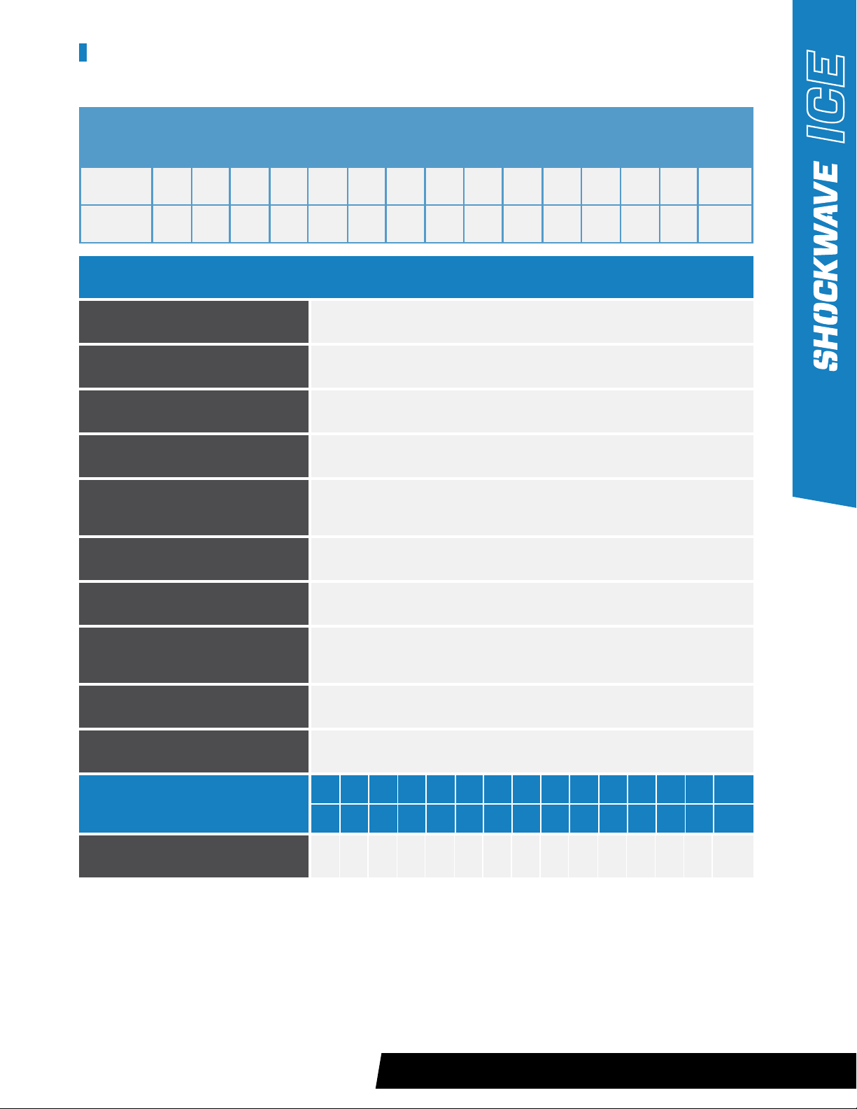
MAINTENANCE SCHEDULE
15 YEAR LIFE CYCLE MAINTENANCE PROGRAM - BASED ON 400 HRS./YR.
Service at the indicated hours or months - whichever comes first.
HOURS
MONTHS
400
12
800
24
1200
36
1600
48
2000
60
2400
72
2800
84
3200
96
3600
108
4000
120
4400
132
4800
144
5200
156
5600
168
6000
180
WHEN NOT BEING USED OR IF STORED OUTSIDE
Cover seating with Boat Cover
or Seat Cover
AFTER EVERY EXPOSURE TO SALT WATER SPRAY
Clean ICE - Fresh Water or
Wash with Car or Boat Wash
EVERY 200 HRS OR AFTER EXPOSURE TO EXTREME IMPACTS
Inspect Shock Mounts and Shock
Bolts for damage or bends
WEEKLY
Lubricate Link Ends – LPS 3, triple
guard grease or equivalent
EVERY 40 HOURS (AFTER SEATS HAVE DRIED FROM CLEAN)
Protect Metal Surfaces and
Fasteners – LPS 1® or equivalent
EVERY 125 HOURS
Check Fastener Torques
EVERY 200 HOURS
Use Soapy water to check for
air leaks
AS REQUIRED (REMOVING ANY BUILDUP OF DIRT OR SALT)
Clean Upholstery – Boat or
Automotive Detail Spray Cleaner
AFTER EVERY EXPOSURE TO SALTWATER SPRAY
Clean Console Underside and Deck
Mounts – Fresh Water or Wash with
Car or Boat Wash
WEEKLY
Clean and Lubricate Fox Shock
Absorber Shaft – After cleaning
apply LPS 1®
HOURS
MONTHS
400
12
800
24
1200
36
1600
48
2000
60
2400
72
2800
84
3200
96
3600
108
4000
120
4400
132
4800
144
5200
156
5600
168
6000
180
X X X X X X X
Replace Link End Heim Joints
MAINTENANCE TASK
MAINTENANCE SCHEDULE

11
Squeaks when in use
Zip tie travel indicator below
“Safe Travel Zone Marker”
• Rod end bearings of the ICE
links are dry
• Sway bar links are dry
• Insufficient air pressure
in shocks
• Console overweight
• Lubricate with heavy duty
marine grease.
• Remove sway bar arm and
lubricate bearing area with
heavy duty marine grease.
• Follow: Finding an air leak on
the subsequent pages.
• Remove excess weight from
the console.
Clunking Noise During Operation • Loose bolts or cracked
components
• Check bolt torques and
inspect for loose, cracked or
bent parts. Start by checking
the upper shock bolts and
work your way down to the
deck, checking all fasteners
and brackets.
CONDITION CAUSE REMEDY
GENERAL TROUBLESHOOTING
GENERAL TROUBLESHOOTING
12
TROUBLESHOOTING – AUTOTUNE OVERVIEW
The AUTOTUNE systems contain valves, hoses, compressors and shocks which work together to manipulate the
SHOCKWAVE ICE with simple toggle switches. While the ICE configurations vary slightly due to body shape and space
availability the general layout is consistent throughout the SHOCKWAVE ICE product line.
• Each shock has two air connections. The fill port is used to add/remove air from the shock. The set port
is used to automatically drain a certain amount of air from the shock to provide the correct ride height.
• The compressor, tank, and water separator are typically located in the rear lower section of the ICE.
• The fill and set solenoid valves are typically located just inside the body of the ICE near the shock mounts.
Each shock has its own ‘FILL’ and ‘SET’ solenoid valve.
• The main fill solenoid valve is typically located near the air/water separator and the main drain solenoid is
typically located near the distribution manifold.
SET PORT
(USED TO OPTIMIZE PERFORMANCE)
FILL PORT
(USED TO ADD/REMOVE AIR)
TROUBLESHOOTING – AUTOTUNE OVERVIEW
13
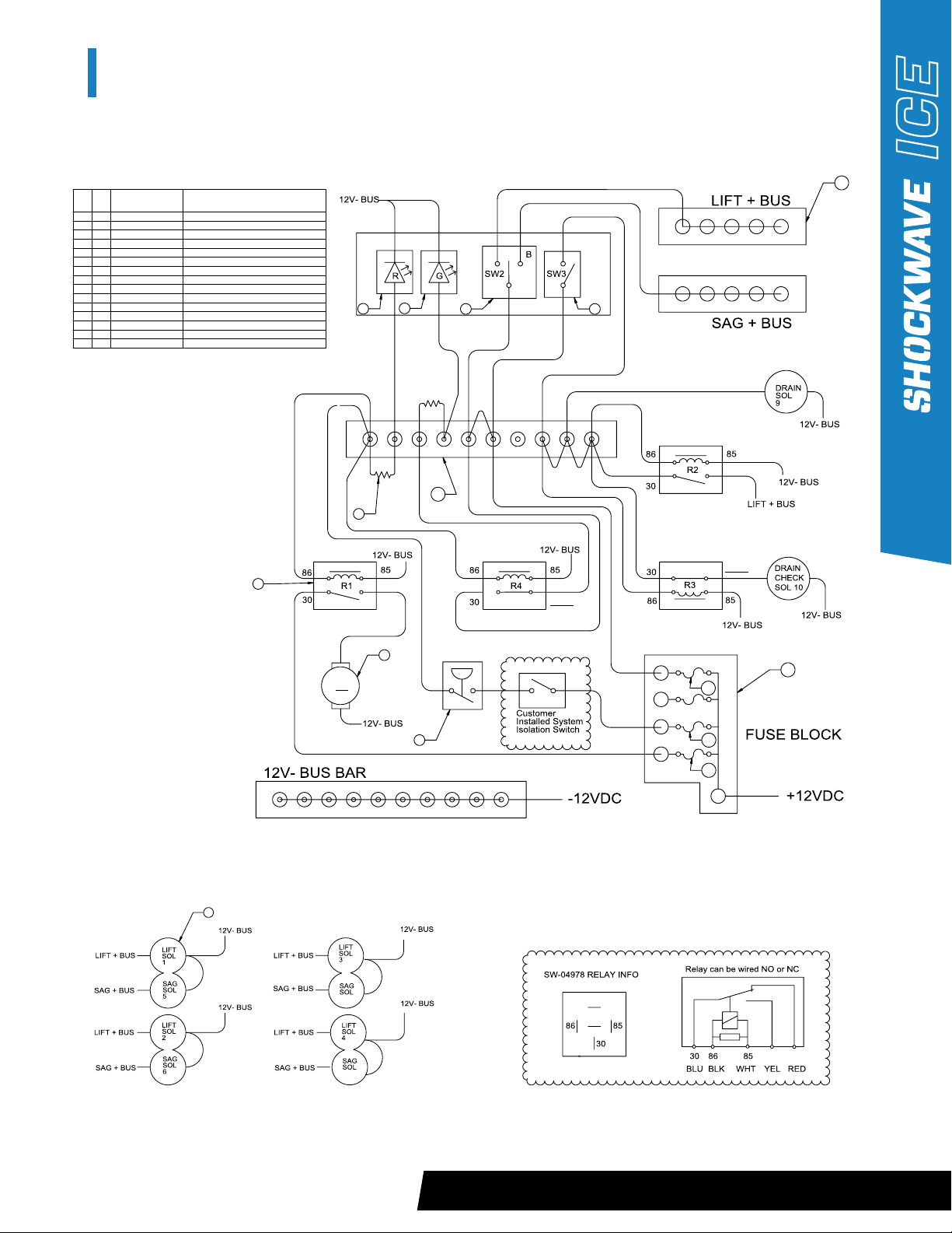
AUTOTUNE 1 TROUBLESHOOTING
ELECTRICAL DIAGRAM
M
A
87
87A**
87A**
87
8
2
3
4
567
9
10
11
12
13
14
15
ITEM
QTY.
PART NO.
DESCRIPTION
110
SW-04968
12V Solenoid Valve - 1/4" NPT Female
21
SW-04973
12V Pressure Switch - 200PSI NC
34
SW-04978
12V 30A Relay With Pigtail
41
SW-04979
12V 4MM Panel Mount LED - Green
51
SW-04980
12V 4MM Panel Mount LED - Red
61
SW-04982
SPDT Harsh Environment Toggle Switch
71
SW-04985
Seadog 30A Push Button Switch
81
SW-05071
VIAIR 480C Air Compressor
92
SW-05098
Resistor 680 Ohm 1 Watt
10 1
NOT SUPPLIED
4 Position ATD/ATC Fuse Block
11 2
NOT SUPPLIED
4 Position - Common Bus Bar
12 1
NOT SUPPLIED
8 Position Terminal Block - No Common
13 1
NOT SUPPLIED
ATD/ATC Fuse - 5A
14 1
NOT SUPPLIED
ATD/ATC Fuse - 20A
15 1
NOT SUPPLIED
ATD/ATC Fuse - 40A
8
7
1
87A**
87
87A**
87
AUTOTUNE 1 TROUBLESHOOTING ELECTRICAL DIAGRAM

14
AUTOTUNE 1 TROUBLESHOOTING
FLOW DIAGRAM
SW-MB005 – MAINTENANCE INSPECTION ON S1, S2 AND S3 CARRIAGE ROLLERS / FEBRUARY, 2016
Y
Y
N
N
Y
Y
N
Y
N
Y
N
Y
N
Y
N
Y
N
Y
N
Y
N
Y
N
PROBLEM
FIXED?
CONFIRM TANK IS
PRESSURIZED USING
PRESSURE GUAGE
TANK
PRESSURIZED?
CONTACT SHOCKWAVE
SUPPORT CODE #1
(TANK NOT PRESSURIZING)
JUMP TERMINALS OF
PRESSURE SWITCH TO
TEST COMPRESSOR
DOES
COMPRESSOR
RUN?
CHECK SYSTEM FOR LEAKS
AND LOOSE HOSES
PROBLEM
FIXED?
CHECK CONNECTIONS AND
CONFIRM 12VDC AT
COMPRESSOR RELAY
CONNECTIONS
OK?
CONTACT SHOCKWAVE
SUPPORT CODE#3
(COMPRESSOR)
REPAIR AS
REQUIRED
FINISH
TOGGLE / PUSH SWITCH
TO ‘DRAIN’
START
DOES ICE CONSOLE
LIFT UNTIL AT FULL
HEIGHT?
TOGGLE SWITCH TO ‘SET’
DOES ICE
DROP TO
SAG HEIGHT?
TOGGLE SWITCH
TO ‘FILL’
CHECK CONNECTIONS AND
12VDC AT SWITCH #2
PROBLEM
FIXED?
CONFIRM OPERATION OF
SOLENOIDS #5-8 AND
CONNECTIONS TO GROUND
DOES ICE
CONSOLE LOWER
TO THE GROUND?
CONFIRM OPERATION OF
SOLENOID #9 AND
CONNECTIONS TO GROUND
CHECK CONNECTIONS
AND 12VDC AT SWITCH #3
PROBLEM
FIXED?
NOTE: ALWAYS CONFIRM POWER
SOURCE IS SWITCHED ON AND
FUNCTIONING CORRECTLY
PROBLEM
FIXED?
PROBLEM
FIXED?
CONTACT SHOCKWAVE
SUPPORT CODE#4
(SOLENOID)
CONTACT SHOCKWAVE
SUPPORT CODE#2 (POSSIBLE LEAK)
CONFIRM OPERATION OF
SOLENOIDS #1-4, 10 AND
CONNECTIONS TO GROUND
See Electrical Diagram on page page 13 for reference.
AUTOTUNE 1 TROUBLESHOOTING FLOW DIAGRAM

15
AUTOTUNE 1 TROUBLESHOOTING
AUTOTUNE 2 TROUBLESHOOTING
System will not fill • Loss of power to the system • Check Autotune fuse
• Ensure wiring is not damaged,
pinched or corroded.
CONDITION CAUSE REMEDY
ON/OFF light won’t illuminate
FILL light will not stop blinking
SET light does not stop blinking
Status lights not illuminating but
system still functioning
• No power to the system
• System cannot reach maximum
operating pressure (MIN 190 PSI)
• System has not detected signifi-
cant air flow during SET process
• Console was not able to get
above the SET point
• Status light shave burnt out
• Dimmer switch turned down
• Check Autotune fuse
• Ensure wiring is not damaged,
pinched or corroded
• Check for air leaks around the
tank, compressor and shocks
• Re-calibrate the system
• Reduce weight in the ICE
• Re-calibrate the system
• Adjust dimmer switch to
maximum brightness
• Remove panel and check for
voltage at LED’s Replace if
necessary
CONDITION CAUSE REMEDY
AUTOTUNE TROUBLESHOOTING
16
TROUBLESHOOTING – FINDING AN AIR LEAK
If there are operational problems with the console bottoming out or not holding air, the procedure below can
help to narrow down the problem.
STEP 1: Fill the system to max pressure using the fill toggle switch on the AUTOTUNE system. Allow the shocks to fully
extend by allowing the compressor to reach maximum pressure (around 200psi on the tank gauge) and record
the tank pressure.
STEP 2: If the red ‘WAIT’ light is illuminated the compressor is running to fill up the air tank. This can take up to 5 minutes.
Once the green ‘READY TO FILL’ light is illuminated the air tank is full.
STEP 3: Allow the console to sit for 3-4hrs or overnight if possible. Do not allow anyone to enter or add gear to the ICE
during this time.
STEP 4: Measure all the shocks on the ICE and record the extended length as well as the tank pressure.
Tank pressure has dropped but
shocks are still measuring the
same extended length.
Tank is still at max pressure but
extended length of one or more
shocks has dropped.
• Potential air leak between
compressor and “FILL” solenoid
• Potential leak of shock or fitting
between “FILL” Solenoid and
“SET” solenoid.
• Check all fittings with soapy
water, replace or tighten any
loose fittings.
• Check the shock body fittings
with soapy water, replace or
tighten any loose fittings. If the
shock is leaking through its main
seal it will need to be removed
and repaired or replaced.
CONDITION CAUSE REMEDY
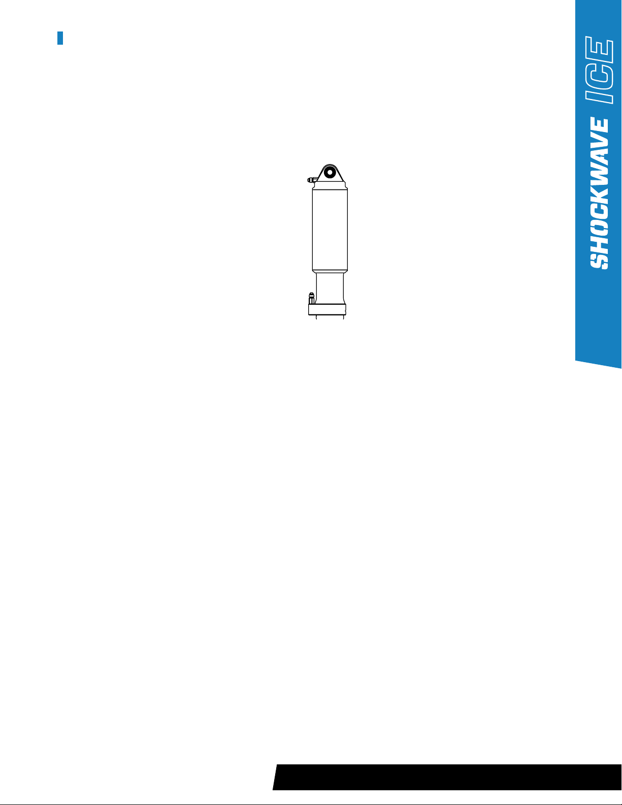
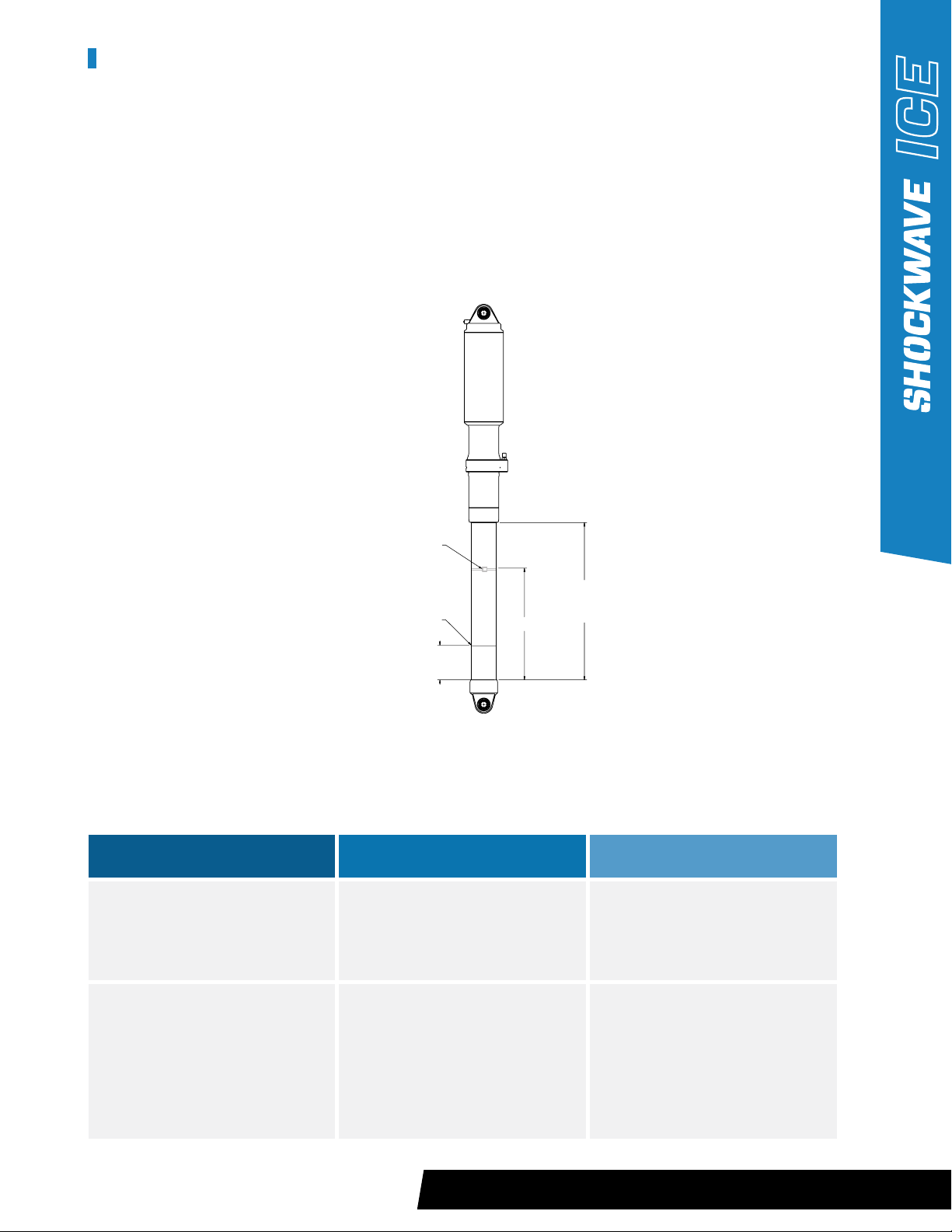
ZIP TIE
SAVE TRAVEL ZONE MARKER
[73mm]
2 7/8”
DIM #1
EXTENDED LENGTH
[354mm]
13-15/16”
TROUBLESHOOTING – FINDING AN AIR LEAK
17
TROUBLESHOOTING – FIXING AN AIR LEAK
STEP 1: Drain the system ensuring the ICE is securely resting on the deck and all the air has been released from the shocks.
STEP 2: If there is obvious damage to the fitting such as a crack or a hole, replace the fitting with a new one sourced
from a hydraulic supply shop or purchase directly from SHOCKWAVE.
STEP 3: Ensure the compressor does not turn on by turning off either the boat power or the auxiliary power switch for
the compressor if supplied.
STEP 4: Remove the leaking fittings, in some instances there are multiple fittings connected to generate the proper
hose routing.
STEP 7: Reinstall all fittings and tighten using the method of flats.
a) Tighten the fitting until it bottoms against the seat.
b) Using a marker, draw a line lengthwise on the fitting and extend it onto the adapter
c) Using a wrench, rotate the fitting to tighten by turning the fitting the 1-1/2 to 1-3/4 hex flat rotations.
STEP 8: If the leak continues, replace the fittings or hoses and repeat steps 6-8.
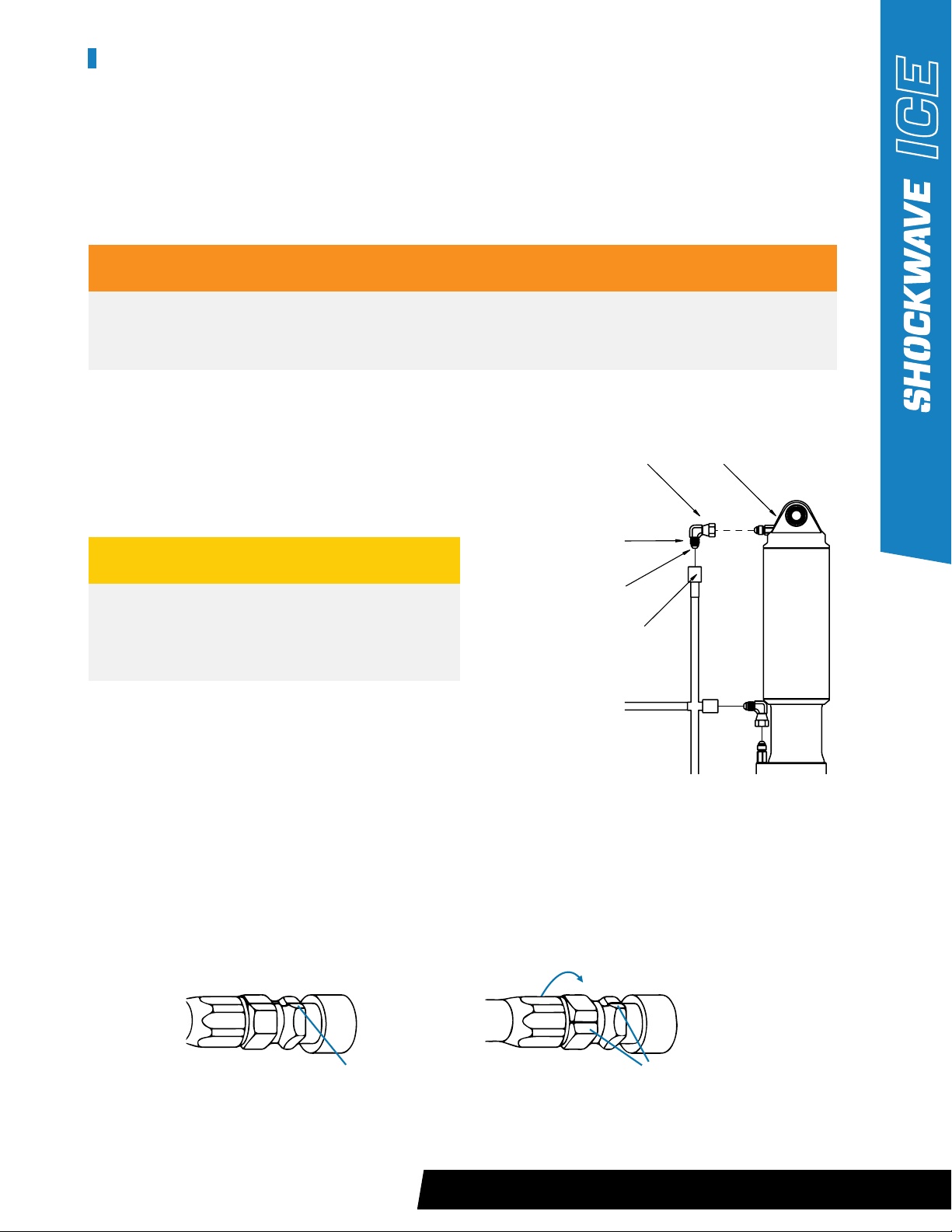
WARNING
When removing combined fittings, always hold both fittings so you only loosen the required fitting.
I.e. Removing Fitting 2 from 1, hold Fitting 1with a wrench and loosen fitting 2 (See drawing below).
THREADS
FITTING 2
FITTING 3
FITTING 1
SEALING FACE
MARK A LINE ON THE FITTING AND
ADAPTER BEFORE TIGHTENING.
MISALIGNMENT OF THE MARK SHOWS
AMOUNT WHICH THE FITTING WAS TIGHTENED.
TROUBLESHOOTING – FIXING AN AIR LEAK
CAUTION
Do not remove Fitting 1 unless there are clear signs
of leakage. If removed, the O-ring on this fitting
needs to be replaced.
STEP 5: Clean the inside and outside of all fittings using a green Scotch-Brite pad or equivalent.
Ensure all contamination is removed from the sealing flanges and threads.
STEP 6: Apply Loctite 5452 to the sealing face (taper) of the fitting and on the threads.
18
TROUBLESHOOTING – SOLENOID
ORIENTATION CHECK
Ensuring that the solenoids are installed correctly is critical to the safety and operational performance of the ICE. To
diagnose the solenoid orientation correctly, the rest of the system must be airtight. Ensure the troubleshooting step
“Finding an Air Leak” (page 16) is completed before proceeding.
STEP 1: Fill the system to max pressure, ensure the tank pressure reads over 190 psi.
STEP 2: Measure and record the extended length of the shock.
STEP 3: Turn off the compressor, this might require the vessel power to be turned off depending on how the system
is powered.
STEP 4: Pull the pressure relief valve on the tank.
Extended shock length has been
reduced.
• Potential incorrect orientation
of the FILL or SET solenoids.
• Install solenoid in the correct
orientation; see AUTOTUNE
Installation Instructions at the
back of this manual.
CONDITION CAUSE REMEDY
TROUBLESHOOTING – SOLENOID ORIENTATION CHECK
CAUTION
Do not put your hands near the pressure relief valve and wear ear and eye protection as the release of air will be
very loud and can potentially cause injury.
STEP 5: Allow the ICE to sit for 3-4 hrs.
STEP 6: Measure the extended length of the shock.
19
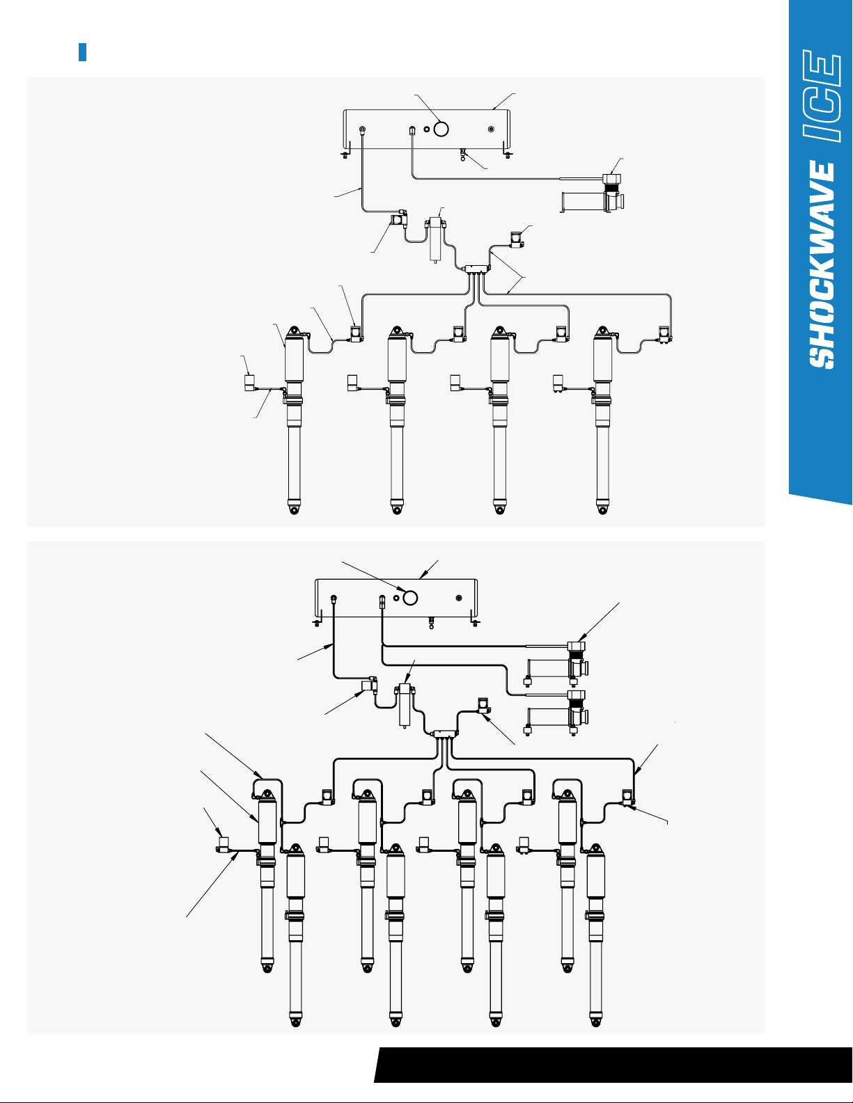
SHOCK CONFIGURATION
‘SET’ SOLENOID (TYPICALLY LOCATED
INSIDE CONSOLE NEAR THE SHOCK)
‘FILL’ SOLENOID (TYPICALLY
LOCATED INSIDE CONSOLE
NEAR THE SHOCK)
LOW PRESSURE PUSH TO CONNECT HOSE AIR/WATER SEPERATOR
AIR COMPRESSOR
MAIN DRAIN SOLENOID
LOW PRESSURE PUSH
TO CONNECT HOSES
PRESSURE GAUGE TANK
MAIN FILL SOLENOID
HIGH PRESSURE
JIC (FLARE) HOSE
MEGAFLOAT SHOCK
HIGH PRESSURE JIC (FLARE) HOSE
SHOCK CONFIGURATION
‘SET’ SOLENOID (TYPICALLY LOCATED
INSIDE CONSOLE NEAR THE SHOCK)
‘FILL’ SOLENOID
(TYPICALLY LOCATED INSIDE CONSOLE NEAR THE SHOCK)
LOW PRESSURE PUSH TO CONNECT HOSE
PRESSURE RELIEF VALVE
AIR/WATER SEPERATOR
AIR COMPRESSOR
MAIN DRAIN SOLENOID
LOW PRESSURE PUSH TO CONNECT HOSES
TANK GAUGE TANK
MAIN FILL SOLENOID
HIGH PRESSURE
JIC (FLARE) HOSE
MEGAFLOAT SHOCK
HIGH PRESSURE JIC (FLARE) HOSE
4-SHOCK SYSTEM
8-SHOCK SYSTEM
20
WARRANTY
SHOCKWAVE Seats expressly warrants that all mechanical seat components in its MARINE AND OTHER and SUSPENSION
SEATS shall be free from defects in material and workmanship for one year from the date-of-sale provided such seats
are subject to normal use and receive proper maintenance. SHOCKWAVE Seats expressly warrants that the cushions and
seat covers shall be free from defectively sewn seams for a period of 90 days or 750 hours of use, whichever comes first,
excluding normal wear and tear. Rips, tears, abrasions and installation damages are not covered by warranty.
Your sole and exclusive remedy against SHOCKWAVE Seats arising from the purchase or use of MARINE AND OTHER
and SUSPENSION SEATS is limited to repair or replacement of defective materials or defective workmanship, after
verification by SHOCKWAVE Seats. Defective product or materials may be requested for return by SHOCKWAVE Seats
for inspection prior to issuing any replacements. Freight charges for returns are to be covered by the user.
All warranty claims shall have prior approval from SHOCKWAVE Seats warranty department and must be accompanied
by the information requested on the following Claim Form. Products will be repaired or replaced at the sole discretion of
SHOCKWAVE Seats.
THESE WARRANTIES WILL BECOME NULL AND VOID IF:
• The ICE is abused or altered
• The ICE is involved in an accident
• The ICE is improperly installed
• The ICE is used for other than its intended use, contrary to any of the instructions in the manual provided.
• There is damage to the ICE caused during installation or unpacking.
• There is damage to the cushions and covers caused by cuts, burns, or abuse
The above expressed warranties shall be the exclusive warranties, and SHOCKWAVE seats
makes no other warranties, expressed or implied. SHOCKWAVE seats expressly disclaims any
implied warranties or merchantability and implied warranties of fitness for a particular purpose.
It is agreed that SHOCKWAVE seats shall not be liable for incidental or consequential damages,
including, but not limited to, loss of income, loss of use, lost profits, damage to other property, the cost of removing
and reinstalling the INDUSTRIAL SEATING or SUSPENSION SEATS, attorney’s fees, and any liability you may have with
respect to any other person.
It is agreed that you have one year from the accrual of a claim to commence any legal action arising from the purchase or
use of the MARINE AND OTHER or SUSPENSION SEATS, or be barred forever.
Failure to give prompt written notice within ten (10) days of the discovery of any defect in material or workmanship that
occurs within the warranty period will void the warranty. Send notification and completed warranty claim form to:
SHOCKWAVE SEATS WARRANTY DEPARTMENT
2074 Henry Avenue West, Sidney BC Canada V8L 5Y1
WARRANTY CLAIM FORM MUST BE SUBMITTED
Download your Warranty Claim Form at shockwaveseats.com/warranty
To the extent any provision of this Limited Warranty contravenes the law of any jurisdiction, such provision shall be
inapplicable in such jurisdiction, and the remainder of this Limited Warranty shall not be affected thereby.
WARRANTY
Table of contents
Other Shockwave Marine Equipment manuals


Popular Marine Equipment manuals by other brands


JRC
JRC JFV-130HP Series installation manual

EMBRON
EMBRON Hatteland Technology HD 15T22 MMD F Series user manual

Nexus
Nexus Autopilot R-1600 Installation and operation manual

Abus
Abus FUSG50110 quick guide

Abus
Abus AZSG10020 Installation instructions and user manual

Edgetech
Edgetech STARMUX IV USER HARDWARE MANUAL

Dura-Max
Dura-Max Box Cooler installation manual

Speedtech
Speedtech EE-1 user manual

vesper marine
vesper marine WatchMate 850 install guide

Simrad
Simrad GN70 Operator and installation manual

Sailmon
Sailmon E4 installation manual

System Sensor
System Sensor MASS12LO Installation and maintenance instructions