SCHOTTEL
SRP 15 .... SRP 300
No.
BA 103 E
Dat.
1-12-77
TD-NM-in
Seitenz.
19
Seite
4
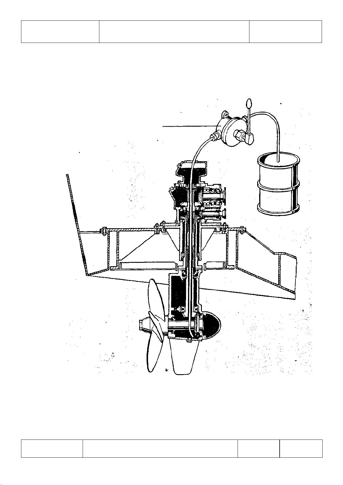
To avoid air from entering the propeller, a cover plate
(Figures 4/2 or 6/2) can be provided. In addition, a nozzle
can be provided for increasing the thrust.
1.3 LUBRICATION
The SRP features oil bath lubrication, i.e. it is filled with
oil. An oil tank, either directly mounted on the SRP or
separately mounted, is used as expansion and compensating tank.
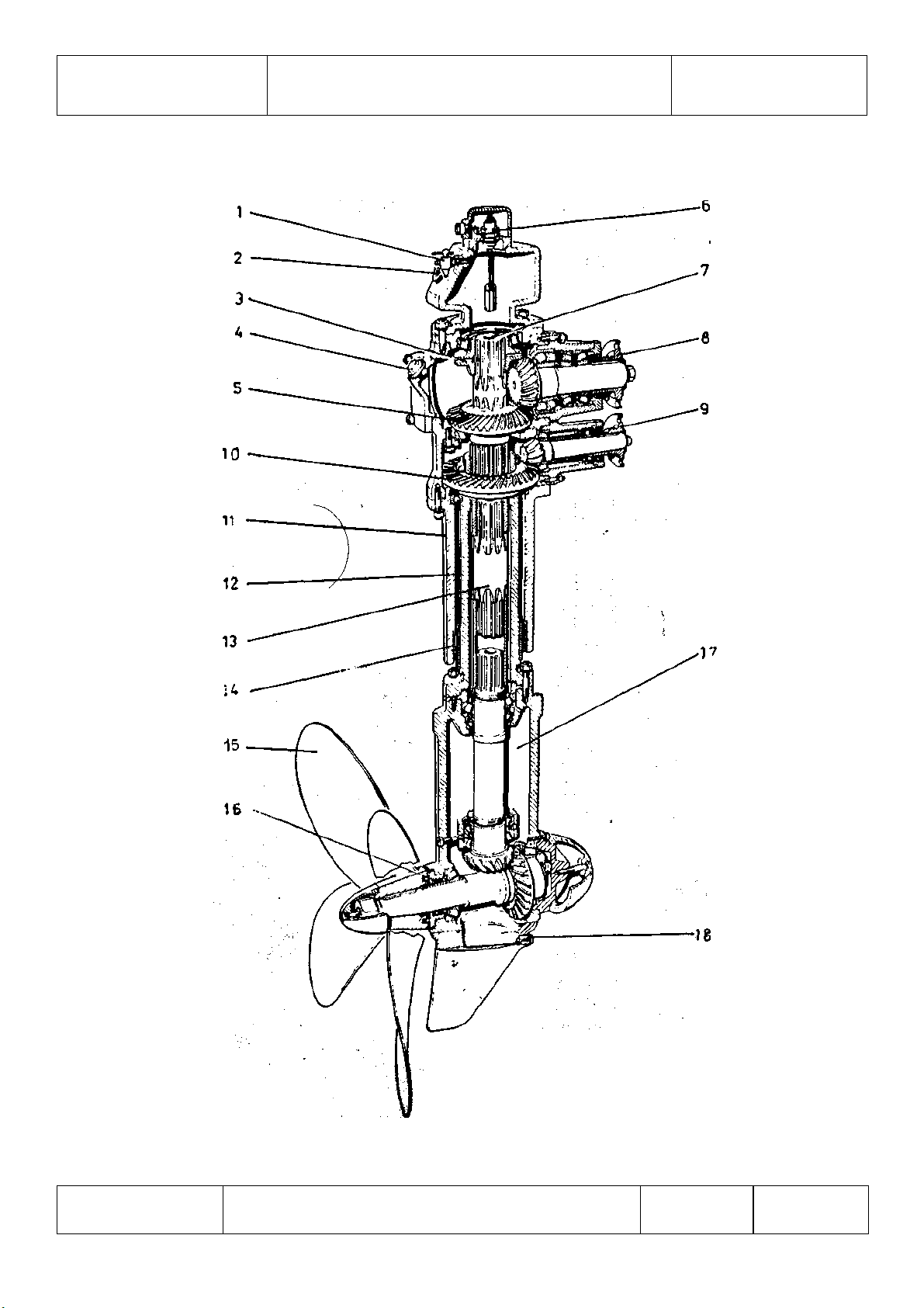
The oil in the SRP is circulated during operation and cooled in
the lower section. The circulation is accomplished by an oil
slinger (Figure 1/3) for sizes up to SRP 100, and by a worm gear
(Figure 7) for sizes SRP 150-300. This oil worm gear is located
on the power transmission shaft and forces the oil down. A
sight-glass (Figure 1/2) on the oil tank and an electric warning
switch (Figure 1/6) are provided for checking the oil level; the
warning switch closes a contact as soon as the specified oil
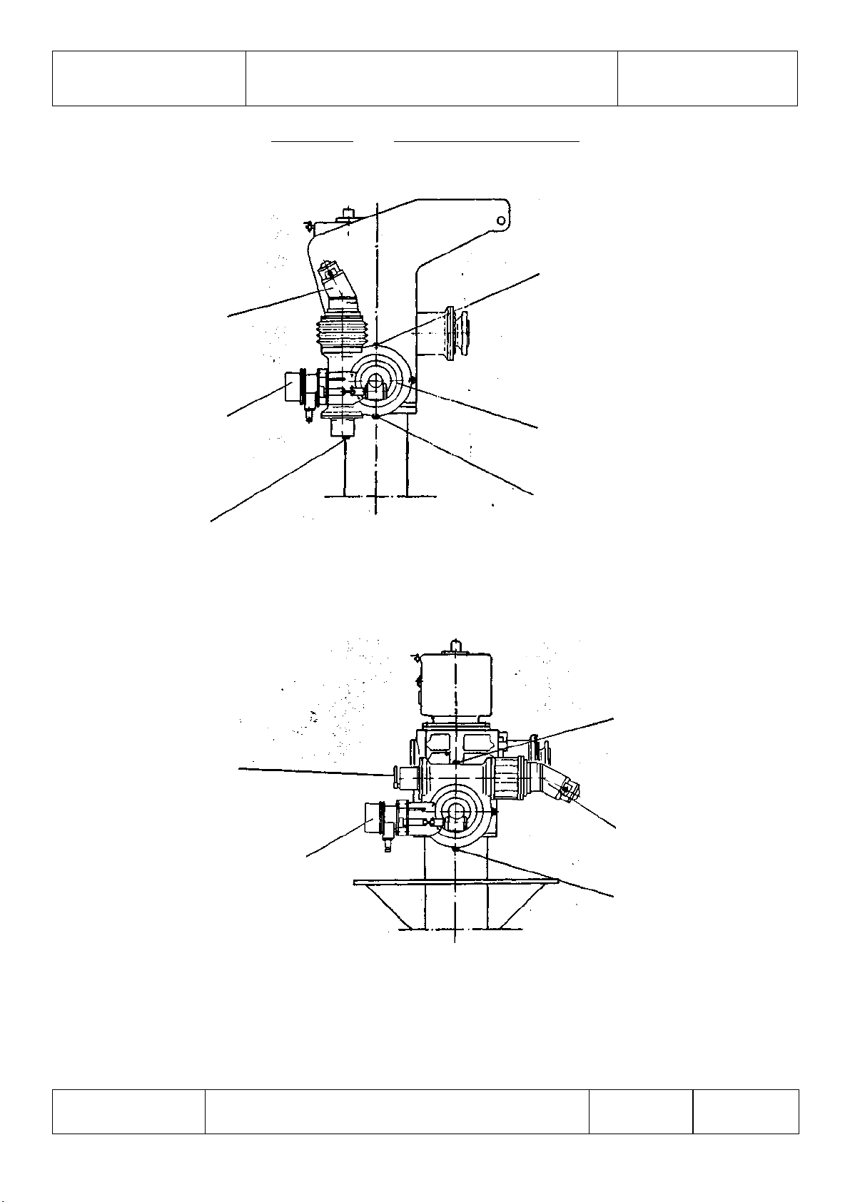
quantity is fallen below. The attached steering worm gear
(Figure 2) are sealed from the upper gearing and are equipped
with a separate oil fill hole.
1.4 COMPENSATING FIN
The torque of the vertical power transmission shaft (Figure 1/13)
is transmitted through the bevel gear pair of the lower gearing
of the SRP to its housing. The torque must be fully absorbed by
the steering gear, unless it is compensated.
For this reason, the manually controlled SRP's (steering systems
S 100, S 200 and S 300) are equipped with compensating fins
(Figures 4/4, 5/1 or 6/4).
1.5 STEERING WORM GEARS (See Figure 2)
One, or, in case of higher outputs, two (DST) worm gears can be
mounted at the side of the upper gearing. The steering drive is
accomplished by a hydraulic motor attached to each worm gear.