Schrack Technik GENIO Dual Maxi Series User manual

USER MANUAL
UNINTERRUPTIBLE POWER SUPPLY
Series GENIO Dual Maxi
Battery boxes
USBB240A3
USBB240A5
USBC240A5

I
NTRODUCTION
Thank you for choosing our product.
The manufacturers are highly specialized in the development and production of uninterruptible
power systems (UPS) and related accessories.
This manual contains the detailed instructions for the use and installation of the BATTERY BOX
for UPSs.
To get the most out of this device, please read these instructions and follow them carefully. Keep
this manual near the BATTERY BOX.
© No part of this manual may be reproduced, even partially, without the manufacturer’s authorization.
For purposes of improvements the manufacturer reserves the right to modify the described product at any time and without notice.

C
ONTENTS
PRESENTATION 4
V
IEWS OF THE
BATTERY
BOX 5
LED
PANEL
(
ONLY FOR VERSIONS WITH BATTERY CHARGER
) 6
D
ESCRIPTION OF OPERATION
6
INSTALLATION 7
O
PENING THE PACKAGING AND CHECKING ITS CONTENTS
7
T
OWER VERSION
8
R
ACK VERSION
9
I
NSTALLATION PROCEDURE
11
C
ONNECTING THE
BATTERY
BOX 11
M
ULTIPLE EXPANSIONS
12
N
OMINAL BATTERY CAPACITY SETTINGS
-
SOFTWARE CONFIGURATION
12
TROUBLESHOOTING 13
TECHNICAL DATA TABLE 14

P
RESENTATION
The new BATTERY BOX family has been designed with versatility in mind. Thus the BATTERY
BOX can be installed in tower or rack version according to requirements by using the handles kit.
The two different versions of the product are shown below:
JSDL240PA3 JSDL240PA5 JSDL240CA5
Nominal capacity [Ah]
7 9 9
Dimensions H x L x P [mm]
455 x 175 x 660
(
1
)
Weight [Kg]
63 65 67
(1)
The H dimension is different in the rack version with handles mounted: 483mm x 175mm x 660mm (H x L x W)
Note: 175mm = 4U
483mm = 19”
Tower Rack

P
RESENTATION
V
IEWS OF THE
BATTERY
BOX
Release slots
Extractable / rotatable
mask
Removable front
panel
Front view
Ventilation grid
IEC 10A input
(only in versions
with battery
charger)
Fuse-holder
disconnecting
switches
Connectors for
battery expansion
Rear view

P
RESENTATION
LED
PANEL
(
ONLY FOR VERSIONS WITH BATTERY CHARGER
)
= MAINS PRESENT LED (green): when lit it means the mains is present.
= BATTERY CHARGER OPERATING LED (yellow): when lit it means the batteries are
being charged
D
ESCRIPTION OF OPERATION
The BATTERY BOX contains the batteries which can increase the operating time of uninterruptible
power systems (UPS) in extended black-out conditions.
The number of batteries contained within can vary depending on the type of UPS the BATTERY
BOX is intended for.
The utmost care must therefore be taken to ensure that the battery voltage of the BATTERY
BOX is the same as the voltage allowed by the UPS.
The BATTERY BOX may contain its own battery charger in optimized switching technology for
the charging of its batteries. The use of a battery charger for each BATTERY BOX allows fast
recharge times to be obtained regardless of the number of batteries and without overloading the
battery chargers within the UPS.
Further BATTERY BOXES could also be connected in parallel to form a chain able to obtain any
amount of back-up time when there is no mains power.

I
NSTALLATION
O
PENING THE PACKAGING AND CHECKING ITS CONTENTS
After opening the packaging, first check the contents.
The packaging should contain the following:
BATTERY BOX
Power cable
(only for models with battery charger)
Battery expansion cable
Handles kit for rack version
3 plastic covers
(upper panels)
2 plastic keys
to release display
2 battery fuses
50A 400V GL
User manual
User's
manual

I
NSTALLATION
T
OWER VERSION
This chapter describes the operations required to prepare the BATTERY BOX for use in the
tower version.
WARNING: for your safety and that of your product, follow the information set out below
exactly.
BEFORE CARRYING OUT THE FOLLOWING SEQUENCE OF OPERATIONS, ENSURE
THAT THE BATTERY BOX IS NOT CONNECTED TO THE ELECTRICITY MAINS, TO
THE UPS OR TO ANY OTHER BATTERY BOXES
Once removed from the packaging, the BATTERY BOX is ready for installation in tower
configuration.
All that is needed to complete this configuration is to mount the 3 plastic covers provided in
the upper part of the BATTERY BOX, as described below:
The 3 covers have an interlocking system:
locate the cover mounting holes in the upper part
of the BATTERY BOX and very carefully engage
them by exerting gentle pressure (see figure at
side).

page
9
I
NSTALLATION
R
ACK VERSION
The sequence of operations required to convert the BATTERY BOX into the rack version is
described below.
WARNING: for your safety and that of your product, follow the information set out below
exactly.
BEFORE CARRYING OUT THE FOLLOWING SEQUENCE OF OPERATIONS, ENSURE
THAT THE BATTERY BOX IS NOT CONNECTED TO THE ELECTRICITY MAINS, TO
THE UPS OR TO ANY OTHER BATTERY BOXES
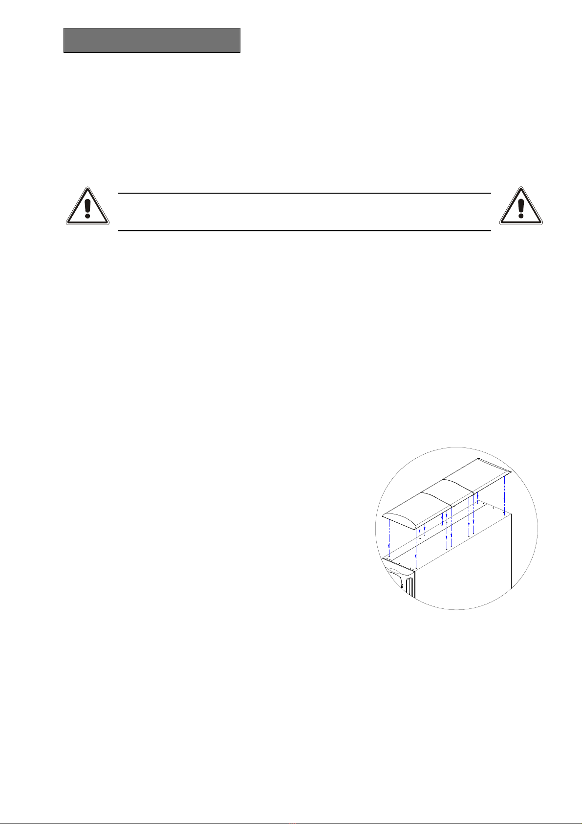
1 - First remove the 4 feet at the base of the
BATTERY BOX. Put the BATTERY
BOX into a horizontal position taking
the utmost care and with a small slotted
screwdriver carefully lift the pin at the
centre of the foot. Once it has been
lifted, remove the foot from the base.
Repeat the same operations for the
remaining feet. The exact sequence to
follow is shown at the side:
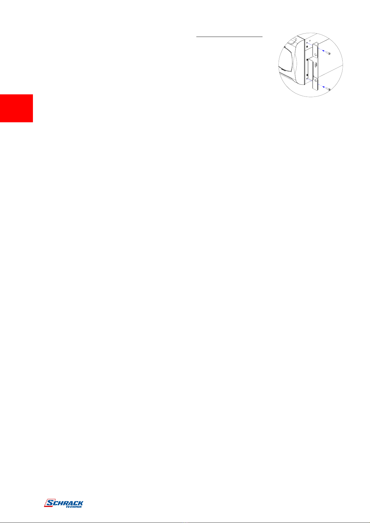
2 - Once all the feet have been removed, the mask must then be
rotated. Insert the keys provided in the release slots located at the
sides of the mask and exert enough gentle pressure to release it from the BATTERY
BOX, as shown in the figure at the side.
3 - (only for the version with battery charger): The mask is connected to the BATTERY
BOX by a specific cable. The mask must therefore be removed with the utmost care
and avoiding violent pulls or other sharp movements so as to avoid any damage to the
LED panel and/or to the actual BATTERY BOX. DO NOT UNDER ANY
CIRCUMSTANCES TRY TO SEPARATE THE MASK FROM THE BATTERY
BOX.
4 - Rotate the mask 90° anticlockwise, carefully insert in the housing and exert gentle
pressure near the release slots until a slight click is heard with the mask remaining in
position.
1 2

page
10
5 - Rotate the BATTERY BOX 90° clockwise taking the utmost care.
6 - At this point, with the BATTERY BOX in a horizontal position,
fasten the handles to the sides with the screws as shown in the
figure at the side.
NOTE: The BATTERY BOX is compatible for mounting in standard rack cabinets of
600mm x 800mm or more (in width). Support brackets (guides with L-shaped
support) must be used in the rack installation due to the weight of the batteries.
Installation in the lower part of the rack cabinet is recommended for the same reason.

page
11
I
NSTALLATION
The company accepts no responsibility for damage caused by wrong connections or by
operations not described in this manual.
The BATTERY BOX electrical specifications are shown on the data plate at the back of the
device.
I
NSTALLATION PROCEDURE
Before connecting the BATTERY BOX to the UPS ensure that the following notes are
complied with:
Install the BATTERY BOX on a flat and stable surface.
Avoid placing it where it will be exposed to direct sunlight or hot air
Keep ambient temperature between 0°C and 40°C
N.B.: the BATTERY BOX can operate with ambient temperature between 0°C and
40°C. The optimal operating temperature of the batteries contained in the BATTERY
BOX is between 20 and 25°C. While the operating life of the batteries is on average 4
years with ambient temperature of 20°C, battery life is halved with the temperature at
30°C.
The ambient relative humidity must not exceed 90%.
Avoid dusty environments.
Take care to position the BATTERY BOX with the front and the back at least 10 cm
from walls and ensure that objects are not placed on the air slots, so as to allow
adequate ventilation.
The cable connecting the BATTERY BOX to the UPS cannot be extended by the user.
The supplier should be contacted if this is required.
C
ONNECTING THE
BATTERY
BOX
Check that the BATTERY BOX battery voltage is the same as the voltage allowed by
the UPS (check the data plate at the back of the BATTERY BOX and the UPS
manual)
Depending on requirements, connect the BATTERY BOX to the UPS or to another
BATTERY BOX by means of the expansion cable provided
Insert the two fuses provided into the fuse-holder disconnecting switches at the back
of the BATTERY BOX. Close the disconnecting switches.
(only for the version with battery charger): connect the power cable to the
BATTERY BOX and o the mains. The LED indicating mains present will light up
immediately. The LED indicating battery charger operating will also light up after a
few seconds’ delay.

page
12
I
NSTALLATION
M
ULTIPLE EXPANSIONS
Several BATTERY BOXES can be connected in a cascade formation (check for any
restrictions in the UPS user manual) for operation with extended back-up time. The
connections should be executed as shown below:
WARNING:
Only one UPS can be connected for each BATTERY BOX or for several cascade-connected
BATTERY BOXES.
N
OMINAL BATTERY CAPACITY SETTINGS
SOFTWARE CONFIGURATION
When one or several BATTERY BOXES have been installed, the UPS must be configured to
update the nominal capacity value (total Ah of batteries within the UPS + external batteries).
The configuration can be carried out using the dedicated UPSTools configuration software,
available on the CD-ROM provided with the UPS.
Installation and execution of UPSTools:
Follow the instructions for installation and use set out in the software manual in the
UPSTools folder of the CD-ROM.
BATTER
Y
EXPANSION
CABLE
UPS BATTERY BOX
Battery Box
BATTERY BOX

page
13
T
ROUBLESHOOTING
Only for models with battery charger
Irregular functioning of the BATTERY BOX is most often not an indication of a fault but due
simply to trivial problems, minor difficulties or carelessness.
We therefore recommend that you refer to the table below which gives a summary of useful
information to solve the most common problems.
PROBLEM POSSIBLE CAUSE SOLUTION
The LEDs on the front
panel do not light up
No mains power
connection cable
Check that the power supply cable is
connected correctly
No mains voltage (black
out)
Check that voltage is present in the plug used
to connect the BATTERY BOX (by trying it
with a table lamp, for example)
Battery charger input
fuse has blown Call SERVICE to replace it
The LINE PRESENT
LED lights up but the
BATTERY CHARGER
OPERATING LED
does not light up or
flickers.
The mains voltage is
low No solution as the unit is operating correctly
Batteries very low
After a long discharge it is necessary to wait a
few minutes before the battery charger starts
operating
There is a short circuit
or overload downstream
of the battery charger.
Possible battery fault. Remove the mains
cable, disconnect the batteries, removing the
fuses at the back, and call SERVICE for a
replacement

page
14
T
ECHNICAL DATA
TABLE
MODELS WITH BATTERY CHARGER JSDL240CA5
INPUT
Nominal voltage [Vac]
220 / 230 / 240
Accepted range [Vac]
190 ÷ 276
Nominal frequency [Hz]
50 – 60
Maximum current
(
1
)
[A]
2
Nominal current
(
2
)
[A]
1,7
BATTERY
Nominal voltage [Vdc]
240
Nominal Ah [Ah]
9
End of charge voltage [Vdc]
273
No. of batteries / V / Ah 20 / 12 / 9 (High Current Discharge Capability)
Recharge time
(
3
)
[h]
8 ÷ 10
VARIOUS
Ambient temperature
(
4
)
[°C]
0 – 40
Humidity < 90% non-condensing
Protections overcurrent – short circuit – overvoltage
Dimensions H x L x W [mm]
455 x 175 x 660
(
5
)
Weight [Kg]
67
BASIC MODELS JSDL240PA3 JSDL240PA5
BATTERY
Nominal voltage [Vdc]
240
Nominal Ah [Ah]
7 9
End of charge voltage [Vdc]
273
No. of batteries / V / Ah 20 / 12 / 7 (High Current
Discharge Capability)
20 / 12 / 9 (High Current
Discharge Capability)
VARIOUS
Ambient temperature
(
4
)
[°C]
0 – 40
Humidity < 90% non-condensing
Protections overcurrent – short circuit
Dimensions H x L x W [mm]
455 x 175 x 660
(
5
)
Weight [Kg]
63 65
(1)
@ minimum voltage of 190Vac, batteries charging
(2)
@ nominal voltage of 230Vac, batteries charging
(3)
Time required to reach 90% of the charge (after a full discharge)
(4)
20-25°C for longer battery life
(5)
Corresponding to: 19” x 4U x 26” (H x L x D)

page
15

MAN_USBB240A3 USBC240xx_EN_2011_03.doc
0MNSDL240NP5LUA
This manual suits for next models
3
Table of contents
Other Schrack Technik UPS manuals

Schrack Technik
Schrack Technik AVARA USMPXPW130 User manual

Schrack Technik
Schrack Technik AVARA Multi USMLT60 User manual

Schrack Technik
Schrack Technik GENIO Flex Plus Rack Series User manual

Schrack Technik
Schrack Technik GENIO Dual Power Series User manual

Schrack Technik
Schrack Technik AVARA MLT Series User manual

Schrack Technik
Schrack Technik AVARA Multi Power Series Instruction sheet

Schrack Technik
Schrack Technik GENIO Dual Power Series Guide

Schrack Technik
Schrack Technik GENIO Tower Plus USSEP VFI 0,7 Guide

Schrack Technik
Schrack Technik GENIO Dual Midi USPRD 1000 VA User manual

Schrack Technik
Schrack Technik AVARA Multi Power Series User manual