Elektro-Automatik PSB Rack 15U User manual

Installationsanleitung
Installation Guide
Schrank
Cabinet
PSB Rack 15U: 09 114 644

3
EN
Installationsanleitung / Installation guide
09114644
DE
Technische Daten
• Typ: EA 15U
• Abmessungen (BxHxT): 60 x ca. 95 x 100 cm
• Ausführung: mit Türen, auf Rollen
• AC-Anschluß: L1+L2+L3+N+PE
• AC-Versorgung: 400 / 480 V (L-L)
• AC-Strom: max. 28 A
• Gewicht: ca. 137 kg (komplett)
• DC-Ausgang/Eingang: 80 V, max. 1080 A, max. 45 kW
Standardkonguration
• Rollen (4 Stück, 2 davon feststellbar)
• Bestückt mit
» 1x PSB 9080-360 3U
• Vorbereitet für die Aufnahme von bis 3 Einheiten
• Not-Aus-Kreis mit
» 1x Not-Aus-Schalter auf Oberseite
» 1x Doppelter Türkontakt-Schalter hinten
» 1x Schraubanschluß für externe Kontakte
• Ethernet-Schnittstellenmodul
• Kabelaufwicklung seitlich
• 5 m Netzkabel mit CEE-Stecker 32 A
• CAN-Schnittstelle im Gerät installiert
• Zwei Schuko-Steckdosen (16 A) auf der Oberseite
• USB-Anschluß auf Oberseite
Installation
Wichtige Hinweise
• Verändern Sie nicht die Netzeingangs-Verdrahtung
bezüglich Leitungslänge, Absicherung und Quer-
schnitt!
• Der Netzanschluß muß extern abgesichert werden!
Aufstellung
Der Schrank wird auf Rollen geliefert, die xiert werden
können und sollen. Die Rollen dienen lediglich zum
Transport bzw. Ortsveränderung des Schrankes. Nach
jeder Ortsveränderung sind diese wieder festzustellen.
Wichtige Hinweise
• Der Schrank darf nur auf horizontalen Flächen
aufgestellt und betrieben werden.
• Der Schrank muß gegen Wegrollen gesichert sein;
neben der Fixierung der Rollen notfalls durch wei-
tere Maßnahmen
Technical specications
• Type: EA 15U
• Dimensions (WxHxD): 60 x approx. 95 x 100 cm
• Model: with rear and front doors, on casters
• AC input connection: L1+L2+L3+N+PE
• AC input voltage: 400 / 480 V (L-L)
• AC current: max. 28 A
• Weight: approx. 137 kg (complete)
• DC output/input ratings: 80 V, max. 1080 A, max. 45 kW
Default conguration
• Casters (4 pieces, 2 of them are lockable)
• Equipped with
» 1x PSB 9080-360 3U
• Prepared for equipping up to 3 units
• Emergency stop circuit with
» 1x emergency stop switch on top of the body
» 1x double door contact on the rear
» 1x screw terminal for external contact(s)
• Ethernet interface module
• Cable roller on the side of the cabinet
• 5 m supply cord with CEE plug 32 A
• CAN interface installed in unit
• Two 230 V outlets (Schuko, 16 A) installed on top side
• USB port installed on top side
Installation
Important notes
• Do not modify the internal wiring, especially not
regarding cross section and cable length!
• The AC supply has to be fused externally!
Positioning
The cabinet is delivered with casters which can be locked.
The casters are allowed to be used while transporting/
moving of the cabinet. After every change of location they
have to be locked again.
Important notes
• The cabinet must only be positioned and operated
on horizontal ground
• The cabinet must be secured against rolling o,
either by locking the casters or further measures
4
EN
Installationsanleitung / Installation guide
09114644
DE
Der Schrank hat ein beträchtliches Gewicht. Stellen Sie
stets sicher, daß Aufstellungsort und Transportweg das
Gewicht des Schrankes plus mehrerer Personen mühelos
tragen können.
AC-Versorgung
Für den AC-Anschluß der Hauptversorgung ist ein 5 m
langes Netzkabel installiert, das unten aus dem Schrank
herausgeführt wird, damit die rückseitige Tür geschlossen
werden kann. Das Kabel kann auf einer der seitlich am
Schrank angebrachten Kabelhalterungen aufgerollt wer-
den. Bei Betrieb des Schrankes mit nur einem installierten
Gerät ist der Anschluß über das mitgelieferte CEE-32 A-
Kabel zulässig. Werden weitere Geräte installiert, ist das
Kabel durch ein entsprechend höher dimensioniertes zu
ersetzen.
Das PSB-Gerät ist intern mit einem 32 A-Automaten
abgesichert, der auf der Vorderseite des Schrankes zu-
gänglich ist. Die beiden 230 V-Steckdosen sind mit einem
16 A-Automaten abgesichert, sowie die Hilfsversorgung
des Not-Aus-Kreises mit einem Doppel-16 A-Automaten.
DC-Ausgang/Eingang
Der Schrank ist für die Aufnahme von einem Gerät vor-
gesehen, welches bei Auslieferung bereits installiert ist.
Sollten zwecks Entnahme eines Gerätes (Reparatur o.
ä.) die Kupferschienen abmontiert werden, so muß später
nach Wiedereinsetzen sichergestellt werden, daß die
Kupferschienen genauso wie vorher und ausreichend
fest montiert werden, da hier Ströme bis zu 1080 A ie-
ßen können.
DC-Lasten bzw. -Quellen werden an den 6 Anschluß-
punkten (M8-Verschraubung) am unteren Ende des
DC-Busses über Leitungen mit passendem Querschnitt
angebunden.
Achtung!
Externe DC-Quellen immer polrichtig anschließen!
Die Geräte haben keinen Schutz gegen Verpolung und
können auch im ausgeschalteten Zustand beschädigt
werden.
Parallelschaltung / Installation weiterer Einheiten
Es können drei weitere identische Einheiten eingescho-
ben werden. Die dazu benötigten AC-Stecker sind im
Schrank vorinstalliert.
Außerdem ist zwecks Parallelschaltung ein DC-Bus in
Form von Kupferschienen vorhanden, an dem die weite-
ren Einheiten nach dem Einschieben leicht angebunden
werden können.
Die für Parallelschaltung außerdem benötigten Master-
Slave-Kabel sind nicht im Lieferumfang enthalten. Dafür
werden handelsübliche Netzwerkkabel der Kategorie 5
verwendet.
The cabinet has a considerable weight. Always make sure
that the ground it is positioned on can carry the cabinet’s
weight plus that of a few persons without diculty.
AC supply
For the connection to AC the cabinet has a 5 m long cable
installed, which is led out through the bottom plate, so the
rear door can be kept closed. The cable can be stored
using the installed cable holder on the side of the cabinet.
When running the cabinet with only the default unit in-
stalled, the AC connection with the included 32 A CEE
cable is permitted. When adding further units, that cable
has to be replaced by one with accordingly increased size.
The PSB unit is internally fused with a 32 A circuit breaker
which is accessible on the front of the cabinet. The extra
230 V outlets are fused with a separate 16 A circuit break-
er, while the internal auxiliary supply for the emergency
stop circuit is fused with a double 16 A CB.
DC input / output
The cabinet is prepared to receive one units which is
already installed upon delivery.
In case of removal (repair etc.) the DC bus bars have to
be dismounted. Later when installing the removed unit
again, it is required to mount the DC bus bars again and
exactly the same way they were mounted before, because
the total current of the cabinet can be up to 1080 A.
DC loads resp. source are connected to the 6 connection
points (M8 nuts/bolts) at the lower end of the DC bus
using cables with suitable cross section.
Attention!
Always connect external DC sources with correct
polarity!
The devices do not have protection against false polarity
and can even be damaged in switched-o state.
Parallel connection / installation of further units
Up to three additional units of identical model can be
installed in the cabinet. The required AC connection is
already available in form of a pre-wired plug.
For the DC side there is a DC bus in form of copper bars
installed to which the freshly installed units can be con-
nected quickly and easily.
Parallel connection is usually done in master-slave mode,
for which the required cables are not included. Standard
network cable of category 5 are used here.

5
EN
Installationsanleitung / Installation guide
09114644
DE
Ein weiteres, erforderliches Kabel für den Share-Bus
ist auch nicht im Lieferumfang des Schrankes oder der
Geräte enthalten, jedoch die zugehörigen Stecker.
Für weitere Information zwecks Parallelschaltung und
-betrieb, sowie den Share-Bus siehe das Handbuch des
PSB-Gerätes.
USB-Anschluß
Der USB-Anschluß auf der Oberseite kann bei Bedarf
und jederzeit verbunden werden. Er ist im Schrank zum
hinteren USB-Anschluß des obersten Gerätes weiter-
verbunden.
230 V-Steckdosen
Die beiden auf der Oberseite angebrachten 230 V-
Steckdosen sind für den Anschluß von entsprechenden
Verbrauchern, z. B. einem PC, gedacht. Sie sind separat
am AC-Hauptanschluß des Schrankes angebunden und
nicht von einer Not-Aus-Abschaltung betroen (siehe
Verdrahtungsplan). Es können Geräte bis max. 16 A
insgesamt angeschlossen werden.
Be- und Entlüftung
Die Belüftung erfolgt über die Vorderseite (Zuluft) und
Rückseite (Abluft). Die Türen sind luftdurchlässig. Hin-
ter dem Schrank muß daher mindestens 50 cm Platz
gelassen werden.
Vorderseite und Rückseite dürfen nicht durch irgendwel-
che Gegenstände abgedeckt sein, die eine Luftzufuhr
verhindern könnten.
Externer Not-Aus-Kontakt
Der Schrank bietet einen internen Not-Aus-Kreis mit
mehreren Öner-Kontakten. Dieser kann durch einen
oder mehrere externe Kontakte (24 V Schaltspannung)
erweitert werden. Dazu ist auf der Rückseite ein zweipo-
liger Schraubanschluß (grau) mit einer Brücke (orange-
farbenes Kabel) zugänglich. Für die Einbindung des/der
externen Kontakte muß die Brücke entfernt werden. Es
sind Kontakte nach Önerprinzip erforderlich.
CAN-Schnittstelle
Für die Fernsteuerung des einen bei Auslieferung ent-
haltenen Gerätes ist eine CAN-Schnittstelle installiert,
die den üblichen Standards bei CAN entsprechend an-
geschlossen werden sollte. Das Kabel kann nur auf der
Unterseite des Schrankes herausgeführt werden.
Another required cable for the Share bus is also not in-
cluded in the scope of delivery, but the connectors are.
This simple two-wire cable can be made by the user.
For further information regarding parallel connection and
operation and Share bus please refer to the user manual
of the PSB device.
USB connection
The USB socket on top of the cabinet can be connected
anytime and if required. It is internally wired to the rear
USB port of the upper unit.
230 V outlets
The two 230 V outlets (Schuko type) on the top of the
cabinet are used to supply typical 230 V devices, such as
a PC. The max. current rating for both is 16A. The outlets
are separately fused and internally directly connected to
the main AC supply (see wiring scheme), so they’re not
aected by an emergency shutdown of the cabinet.
Air cooling
Operating the cabinet requires unobstructed air ventila-
tion from the front to the back. The installed doors have
a mesh which allows for sucient air circulation. Behind
the cabinet it requires to have at least 50 cm of space
for exhausting air.
Front and back door must not be obstructed in any way.
External emergency stop contact
The cabinet features an emergency stop circuit with mul-
tiple breaker contacts. These can be extended by one or
several external contacts (24 V line). On the rear side,
below the AC input terminal, there is a two-pole screw
terminal (grey) which is bridged by an orange cable.
This bridge has to be removed to implement the external
contacts. They are required to be breakers.
CAN interface
For remote control there is a CAN interface installed in
the one unit that is included in the cabinet upon delivery.
This interface is connected in the typical way according
to CAN standard. The connection cable can only be led
out on the bottom side of the cabinet.

6
EN
Installationsanleitung / Installation guide
09114644
DE
Betrieb
Achtung! Lebensgefahr!
• Beim Betrieb elektrischer Geräte
stehen zwangsweise bestimmte Teile
unter teils gefährlicher Spannung.
Daher sind alle spannungsführenden
Teile abzudecken!
• Alle Arbeiten an den Anschlussklem-
men müssen im spannungslosen Zu-
stand des Gerätes erfolgen (Eingang
nicht verbunden mit Spannungsquel-
len) und dürfen nur von Personen
durchgeführt werden, die mit den
Gefahren des elektrischen Stroms
vertraut sind oder unterrichtet wurden!
Unsachgemäßer Umgang mit diesen
Geräten kann zu tödlichen Verletzun-
gen, sowie erheblichen Sachschäden
führen.
• Berühren Sie die Kontakte am Netz-
kabel oder der Netzanschlußbuchse
nie direkt nach dem Entfernen des
Kabels aus der Steckdose oder dem
Hauptanschluß, da die Gefahr eines
Stromschlags besteht!
• Da einige Geräte im Schrank Senken
sind und einen Eingang haben, kann
an diesem selbst bei Trennung der
AC-Versorgung noch berührungsge-
fährliche Spannung von einer externen
Quelle anliegen!
Operation
Mortal danger - Hazardous
voltage
• Electrical equipment operation means
that some parts can be under danger-
ous voltage. Therefore all parts under
voltage must be covered!
• All work on connections must be car-
ried out under zero voltage (input not
connected to source) and may only be
performed by qualied and informed
persons. Improper actions can cause
fatal injury as well as serious material
damage.
• Never touch cables or connectors di-
rectly after disconnecting from mains
supply, as there is risk of electric shock
due to not yet fully discharged capac-
itors!
• Some of the devices in the cabinet are
sinks, which are supplied voltage from
external sources. Even in situations
where the cabinet is disconnected from
AC supply hazardous voltage could still
supplied to the DC bus by a source!

7
EN
Installationsanleitung / Installation guide
09114644
DE
• Das Gerät ist ausschließlich seiner Bestim-
mung gemäß zu verwenden!
• Das Gerät ist nur für den Betrieb innerhalb
der auf dem Typenschild angegebenen
Anschlußwerte und technischen Daten
zugelassen.
• Führen Sie keine mechanischen Teile,
insbesondere aus Metall, durch die Lüf-
tungsschlitze in das Gerät ein.
• Vermeiden Sie die Verwendung von Flüs-
sigkeiten aller Art in der Nähe des Gerätes,
diese könnten in das Gerät gelangen.
Schützen Sie das Gerät vor Nässe, Feuch-
tigkeit und Kondensation.
• Für Netzgeräte und Batterielader: Schlie-
ßen Sie Verbraucher, vor allem niederoh-
mige, nie bei eingeschaltetem Leistungs-
ausgang an, es können Funken und
dadurch Verbrennungen an den Händen,
sowie Beschädigungen am Gerät und am
Verbraucher entstehen!
• Für elektronische Lasten: Schließen Sie
Spannungsquellen nie bei eingeschaltetem
Leistungseingang an, es können Funken
und dadurch Verbrennungen an den Hän-
den, sowie hohe Spannungsspitzen und
Beschädigungen am Gerät und an der
Quelle entstehen!
• Um Schnittstellenkarten oder -module in
dem dafür vorgesehenen Einschub (Slot)
zu bestücken, müssen die einschlägigen
ESD –Vorschriften beachtet werden.
• Nur im ausgeschalteten Zustand darf eine
Schnittstellenkarte bzw. -modul aus dem
Einschub herausgenommen oder bestückt
werden. Eine Önung des Gerätes ist nicht
erforderlich.
• Keine externen Spannungsquellen mit um-
gekehrter Polarität am DC-Ausgang bzw.
DC-Eingang anschließen! Das Gerät wird
dadurch beschädigt.
• Für elektronische Lasten: keine Span-
nungsquelle am DC-Eingang anschließen,
die eine Spannung erzeugen kann, die
höher ist als 110% der Nenneingangs-
spannung der Last. Das Gerät ist gegen
Überspannungen nicht geschützt, diese
können das Gerät zerstören.
• Niemals Netzwerkkabel, die mit dem Ether-
net oder dessen Komponenten verbunden
sind, in die Master-Slave-Buchsen auf der
Rückseite stecken!
• The equipment must only be used as
intended
• The equipment is only approved for use
within the connection limits stated on the
product label.
• Do not insert any object, particularly metal-
lic, through the ventilator slots
• Avoid any use of liquids near the equip-
ment. Protect the device from wet, damp
and condensation.
• For power supplies and battery chargers:
do not connect users, particularly low re-
sistance, to devices under power; sparking
may occur which can cause burns as well
as damage to the equipment and to the
user.
• Do not connect DC power sources to
electronic load devices while the input is
switched on. Sparking may occur which
can cause burns as well as damage to the
equipment and to the source.
• ESD regulations must be applied when
plugging interface cards or modules into
the relative slot
• Interface cards or modules may only be
attached or removed after the device is
switched o. It is not necessary to open
the device.
• Do not connect external power sources with
reversed polarity to DC input or outputs!
The equipment will be damaged.
• Do not connect a power source to the DC
input which can generate a voltage more
than 110% of the nominal input voltage of
the load. The equipment is not protected
against over voltage and may be irrepara-
bly damaged.
• Never insert a network cable which is con-
nected to Ethernet or its components into
the master-slave socket on the back side
of the device!

8
EN
Installationsanleitung / Installation guide
09114644
DE
Verantwortung des Bedieners
Das Gerät bendet sich im gewerblichen Einsatz. Das
Personal unterliegt daher den gesetzlichen Pichten zur
Arbeitssicherheit. Neben den Warn- und Sicherheitshin-
weisen in dieser Anleitung müssen die für den Einsatz-
bereich gültigen Sicherheits-, Unfallverhütungs- und Um-
weltschutzvorschriften eingehalten werden. Insbesondere
gilt, daß die das Gerät bedienenden Personen:
• sich über die geltenden Arbeitsschutzbestimmungen
informieren.
• die zugewiesenen Zuständigkeiten für die Bedienung,
Wartung und Reinigung des Gerätes ordnungsgemäß
wahrnehmen.
• vor Arbeitsbeginn die Betriebsanleitung vollständig
gelesen und verstanden haben.
• die vorgeschriebenen und empfohlenen Schutzausrü-
stungen anwenden.
• Weiterhin ist jeder an dem Gerät Beschäftigte in seinem
Zuständigkeitsumfang dafür verantwortlich, daß das
Gerät stets in technisch einwandfreiem Zustand ist.
Pichten des Betreibers
Betreiber ist jede natürliche oder juristische Person, die
das Gerät nutzt oder Dritten zur Anwendung überläßt und
während der Nutzung für die Sicherheit des Benutzers,
des Personals oder Dritter verantwortlich ist.
Das Gerät wird im gewerblichen Bereich eingesetzt. Der
Betreiber des Gerätes unterliegt daher den gesetzlichen
Pichten zur Arbeitssicherheit. Neben den Warn- und
Sicherheitshinweisen in dieser Anleitung müssen die für
den Einsatzbereich des Gerätes gültigen Sicherheits-,
Unfallverhütungs- und Umweltschutzvorschriften einge-
halten werden. Insbesondere muß der Betreiber:
• sich über die geltenden Arbeitsschutzbestimmungen
informieren.
• durch eine Gefährdungsbeurteilung mögliche zusätz-
liche Gefahren ermitteln, die sich durch die speziellen
Anwendungsbedingungen am Einsatzort des Gerätes
ergeben.
• in Betriebsanweisungen die notwendigen Verhaltensan-
forderungen für den Betrieb des Gerätes am Einsatzort
umsetzen.
• während der gesamten Einsatzzeit des Gerätes re-
gelmäßig prüfen, ob die von ihm erstellten Betriebs-
anweisungen dem aktuellen Stand der Regelwerke
entsprechen.
• die Betriebsanweisungen, sofern erforderlich, an neue
Vorschriften, Standards und Einsatzbedingungen an-
passen.
• die Zuständigkeiten für die Installation, Bedienung,
Wartung und Reinigung des Gerätes eindeutig und
unmißverständlich regeln.
• dafür sorgen, daß alle Mitarbeiter, die an dem Gerät
beschäftigt sind, die Betriebsanleitung gelesen und ver-
standen haben. Darüber hinaus muss er das Personal
in regelmäßigen Abständen im Umgang mit dem Gerät
schulen und über die möglichen Gefahren informieren.
Responsibility of the user
The equipment is in industrial operation. Therefore the
operators are governed by the legal safety regulations.
Alongside the warning and safety notices in this manual
the relevant safety, accident prevention and environmen-
tal regulations must also be applied. In particular the
users of the equipment:
• must be informed of the relevant job safety require-
ments
• must work to the dened responsibilities for operation,
maintenance and cleaning of the equipment
• before starting work must have read and understood
the operating manual
• must use the designated and recommended safety
equipment.
• Furthermore, anyone working with the equipment is
responsible for ensuring that the device is at all times
technically t for use.
Responsibility of the operator
Operator is any natural or legal person who uses the
equipment or delegates the usage to a third party, and
is responsible during its usage for the safety of the user,
other personnel or third parties.
The equipment is in industrial operation. Therefore the
operators are governed by the legal safety regulations.
Alongside the warning and safety notices in this manual
the relevant safety, accident prevention and environmen-
tal regulations must also be applied. In particular the
operator has to
• be acquainted with the relevant job safety requirements
• identify other possible dangers arising from the spe-
cic usage conditions at the work station via a risk
assessment
• introduce the necessary steps in the operating proce-
dures for the local conditions
• regularly control that the operating procedures are
current
• update the operating procedures where necessary to
reect changes in regulation, standards or operating
conditions.
• dene clearly and unambiguously the responsibilities for
operation, maintenance and cleaning of the equipment.
• ensure that all employees who use the equipment
have read and understood the manual. Furthermore
the users are to be regularly schooled in working with
the equipment and the possible dangers.
• provide all personnel who work with the equipment with
the designated and recommended safety equipment
• install an external device (e .g. according to section 5.2
of IEC/EN 60204-1) which enables the cabinet to be
disconnect from any power source

9
EN
Installationsanleitung / Installation guide
09114644
DE
• dem mit Arbeiten an dem Gerät beauftragten Personal
die vorgeschriebenen und empfohlenen Schutzausrü-
stungen bereitstellen.
Weiterhin ist der Betreiber dafür verantwortlich, daß das
Gerät stets in einem technisch einwandfreien Zustand ist.
Anforderungen an das Bedienpersonal
Jegliche Tätigkeiten an Geräten dieser Art dürfen nur
Personen ausüben, die ihre Arbeit ordnungsgemäß und
zuverlässig ausführen können und den jeweils benannten
Anforderungen entsprechen.
• Personen, deren Reaktionsfähigkeit beeinußt ist, z.
B. durch Drogen, Alkohol oder Medikamente, dürfen
keine Arbeiten ausführen.
• Beim Personaleinsatz immer die am Einsatzort gel-
tenden alters- und berufsspezischen Vorschriften
beachten.
Verletzungsgefahr bei unzureichender
Qualikation!
Unsachgemäßes Arbeiten kann zu Perso-
nen- und Sachschäden führen. Jegliche
Tätigkeiten dürfen nur Personen ausführen,
welche die erforderliche Ausbildung, das
notwendige Wissen und die Erfahrung dafür
besitzen.
Als unterwiesenes Personal gelten Personen, die
vom Betreiber über die ihnen übertragenen Aufgaben
und möglichen Gefahren ausführlich und nachweislich
unterrichtet wurden.
Als Fachpersonal gilt, wer aufgrund seiner beruichen
Ausbildung, Kenntnisse und Erfahrungen sowie Kenntnis
der einschlägigen Bestimmungen in der Lage ist, die
übertragenen Arbeiten ordnungsgemäß auszuführen,
mögliche Gefahren selbständig zu erkennen und Perso-
nen- oder Sachschäden zu vermeiden.
Bedienung der Geräte
Siehe separates Geräte-Handbuch auf dem beiliegenden
USB-Stick.
Fernsteuerung über USB
Siehe Dokumentation (Programmieranleitung) auf dem
beiliegenden USB-Stick. Alternativ kann die ebenfalls
auf dem USB-Stick bendliche Windows-Software EA
Power Control verwendet werden, um das Gerät bzw. den
Master (falls mehrere Geräte installiert sind) zu steuern
oder auch zu kongurieren.
Fernsteuerung über CAN
Siehe Dokumentation (Programmieranleitung) auf dem
beiliegenden USB-Stick.
Furthermore, the operator is responsible for ensuring that
the device is at all times technically t for use.
User requirements
Any activity with equipment of this type may only be per-
formed by persons who are able to work correctly and
reliably and satisfy the requirements of the job.
• Persons whose reaction capability is negatively inu-
enced by e.g. drugs, alcohol or medication may not
operate the equipment.
• Age or job related regulations valid at the operating site
must always be applied.
Danger for unqualied users
Improper operation can cause person or
object damage. Only persons who have the
necessary training, knowledge and experi-
ence may use the equipment.
“Delegated persons” are those who have been prop-
erly and demonstrably instructed in their tasks and the
attendant dangers.
“Qualied persons” are those who are able through
training, knowledge and experience as well as knowledge
of the specic details to carry out all the required tasks,
identify dangers and avoid personal and other risks.
Handling of the devices
See separate user manual for the PSB device on the
included USB stick.
Remote control via USB
See documentation (programming guide) on the included
USB stick. Alternatively, there is the software EA Power
Control, which is on the USB stick as well and which can
be used to remotely congure or control the device or the
master, in case multiple units are installed.
Remote control via CAN
See documentation (programming guide) on the included
USB stick.

10
EN
Installationsanleitung / Installation guide
09114644
DE
Ansichten & Aufteilung Views & Layout
Vorderansicht / Front view
Page
1 von 3
E
A
EA - Elektro
Automatik
Rev‘d :
Created :
Date Name
CAD System Microsoft Visio
Artikel Nr. : 09114644
File name :
Checked :
Date NameChange notice
09114644_AA-Ansicht_02.vsdx
04.08.2017 H.Füllgrabe EA-PSB Rack 15 HE für 1x
PSB 9080-360 3U, Not-Aus
Steckdosen, USB Füllgrabe04.09.2017
ABB
1 ON
ABB
1 ON
ABB ABB ABB
1 ON 1 ON 1 ON
ABB
1 ON
ABB ABB ABB
1 ON 1 ON 1 ON
ABB ABB ABB
1 ON 1 ON 1 ON
F1
Unit 1
F2
Unit 2
1
0
POWER SUPPLY
PSB 9080-360 3U
0... 80V / 0. ..36 0A
0... 1500 0W
Cursor Position
USB
On Off
On / Off
On Off
On / Off
Cursor Position
0.00 V
0.00 A
0kW
48.00 V
1530.0 A
45.00 kW
UI
F4
Unit 4
PSB 9080-360
Unit 1
F2
Unit 3
F5
MENNEKES
220/346 V
240/415 V
3P –N -
GKG
IP
44 14A

11
EN
Installationsanleitung / Installation guide
09114644
DE
Rückansicht / Rear view
Page
2 von 3
E
A
EA - Elektro
Automatik
Rev‘d :
Created :
Date Name
CAD System Microsoft Visio
Artikel Nr. : 09114644
File name :
Checked :
Date NameChange notice
09114644_AA-Ansicht_02.vsdx
04.08.2017 H.Füllgrabe EA-PSB Rack 15 HE für 1x
PSB 9080-360 3U, Not-Aus
Steckdosen, USB Füllgrabe04.09.2017
L2L1 L3 PE
Ana lo g
Interface
USB
1
12
13
24
GP IB
C&K
Shar e Sens e
- +
L3
L2
L1
Master / Slave !
L3
L2
L1N
L3
L2
L1N
COMMUNICATION PORT
Digit al
Interface
USB
Ana log
Interface
N
MENNEKES
220/346 V
240/415 V
3P –N -
GKG
IP
44 14A

12
EN
Installationsanleitung / Installation guide
09114644
DE
E
A
EA - Elektro
Automatik
Rev‘d :
Created :
Date Name
CAD System Microsoft Visio
Artikel Nr. : 09114644
File name :
Checked :
Date NameChange notice
09114644
04.08.2017 H.Füllgrabe EA-PSB Rack
PSB 9080-360 3
Steckdosen, USB Füllgrabe04.09.2017
Front
USB
Unit 1
Ansicht von oben/ Top view
13
EN
Installationsanleitung / Installation guide
09114644
DE
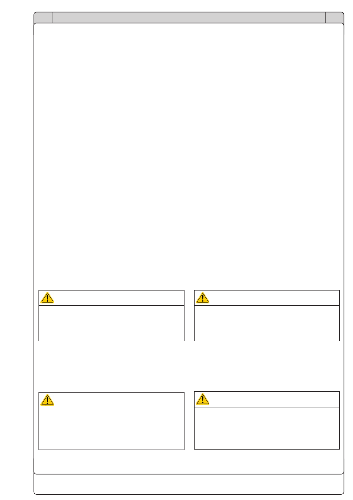
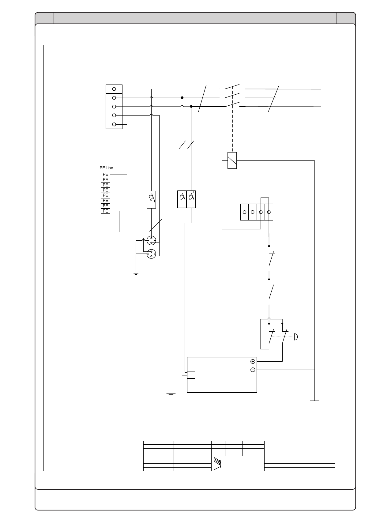
Verdrahtungsplan Wiring schematic
Pa ge
1 vo n 2
E
AEA - E l ekt r o Au to ma ti k
EA--PSB Rack 15 HE für 1x
PSB 9080-360 3U , Not-Aus
Rev ‘d :
Created :
Da te Name
CAD Sy stem Mi croso ft V isio
A rt i k e l N r . : 09114644
File name :
Checked :
Da te Na meChan ge notice
Füllgrabe
09114644_VP_02.vsd
04.09.2017
07.08.2017 Füllgrabe
20.09.2017 S ta be r oc k
S te c kd o se , USB
Einspeisung
Klemmen /
Supply
cl amps
4 x 35 mm2
Empfohlene
Absicherung /
Recommended fusing:
32A
X10
PE-Verteilung
L1
PE
L3
L2
X 1
L1
L2
L3
blk
blk
blk
gn/ge
Netzkabel 5 x 4mm2
5m lang /
power cord 5 x 4mm2
length 5m
A2
A1
K1
X1
MW-WDR-120-24
Unit 4
L1/L2/ PE
S1
Emergency stop switch
16A16A
Brücke ext. Not-Aus /
Bridge ext. emergency stop
S2
doo r c ontact s witch bo tt om
24V=
F4
black
black
8L2
8L3
H07V-K
16 mm2
12L2
12L3
black
black
Ye/gn
22
2
1
1
9
3
2
4
5
orange
orange-w hi te
orange
orange
SC2.1
1.5mm2
SC2.1
1.5mm2
SC2.1
1,5mm2
1
3
5
2
4
6
2L1
2L2
2L3
black
black
black
X2.1 –X2.4
ye/gn 13
S3
doo r contact switch top
orange-w hi te
orange-w h i te
7
orange SC2.1
1,5mm2
8
orange
1
2
22
21
21
orange
H07V-K
2,5mm2
H07V-K
Blk 16mm2
H07V-K
16mm2
16A
F5
N
H07V-K 2,5mm2
X5
H07V-K 16 mm2
blue 1N
black 8L1
black 9L1
14
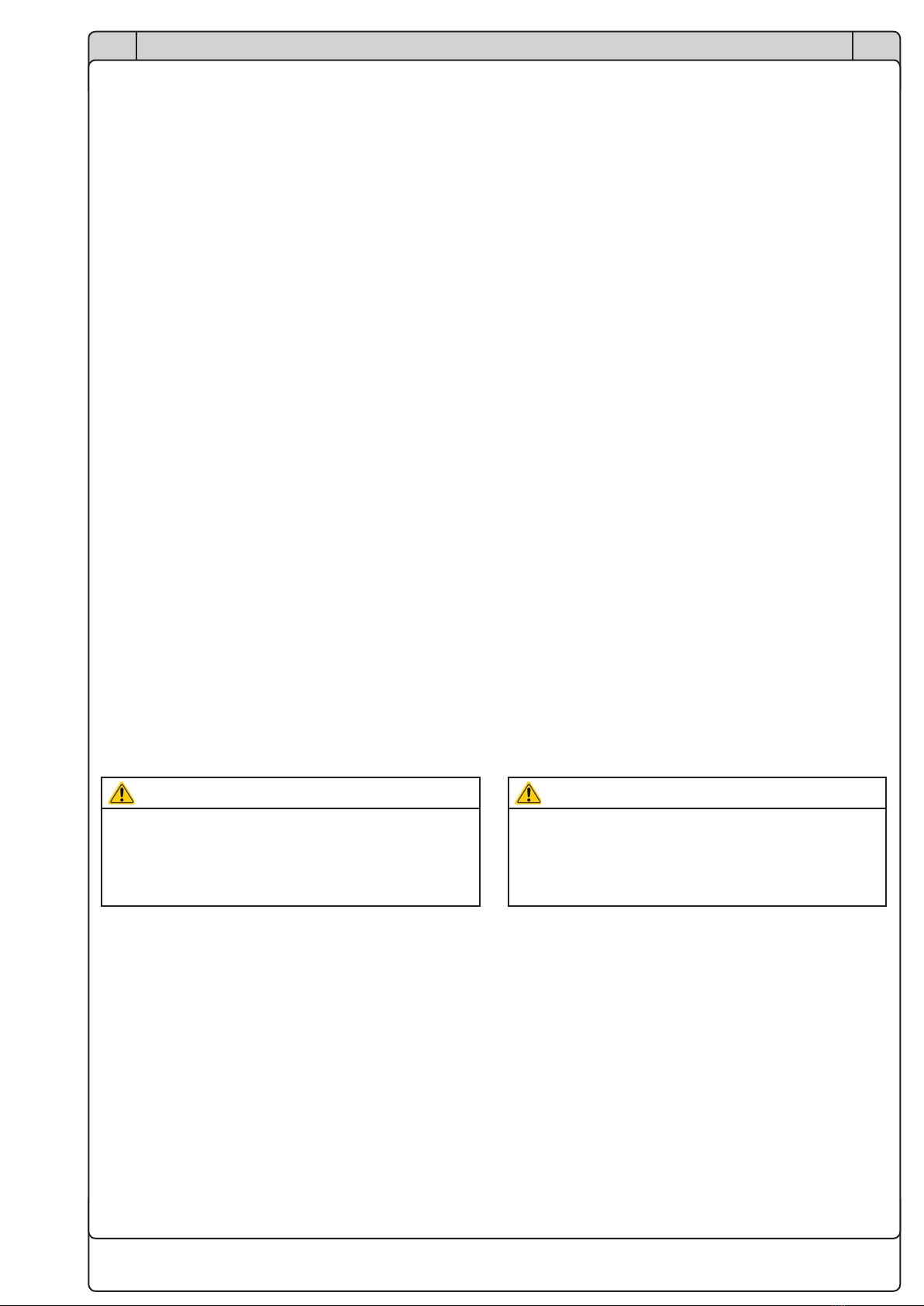
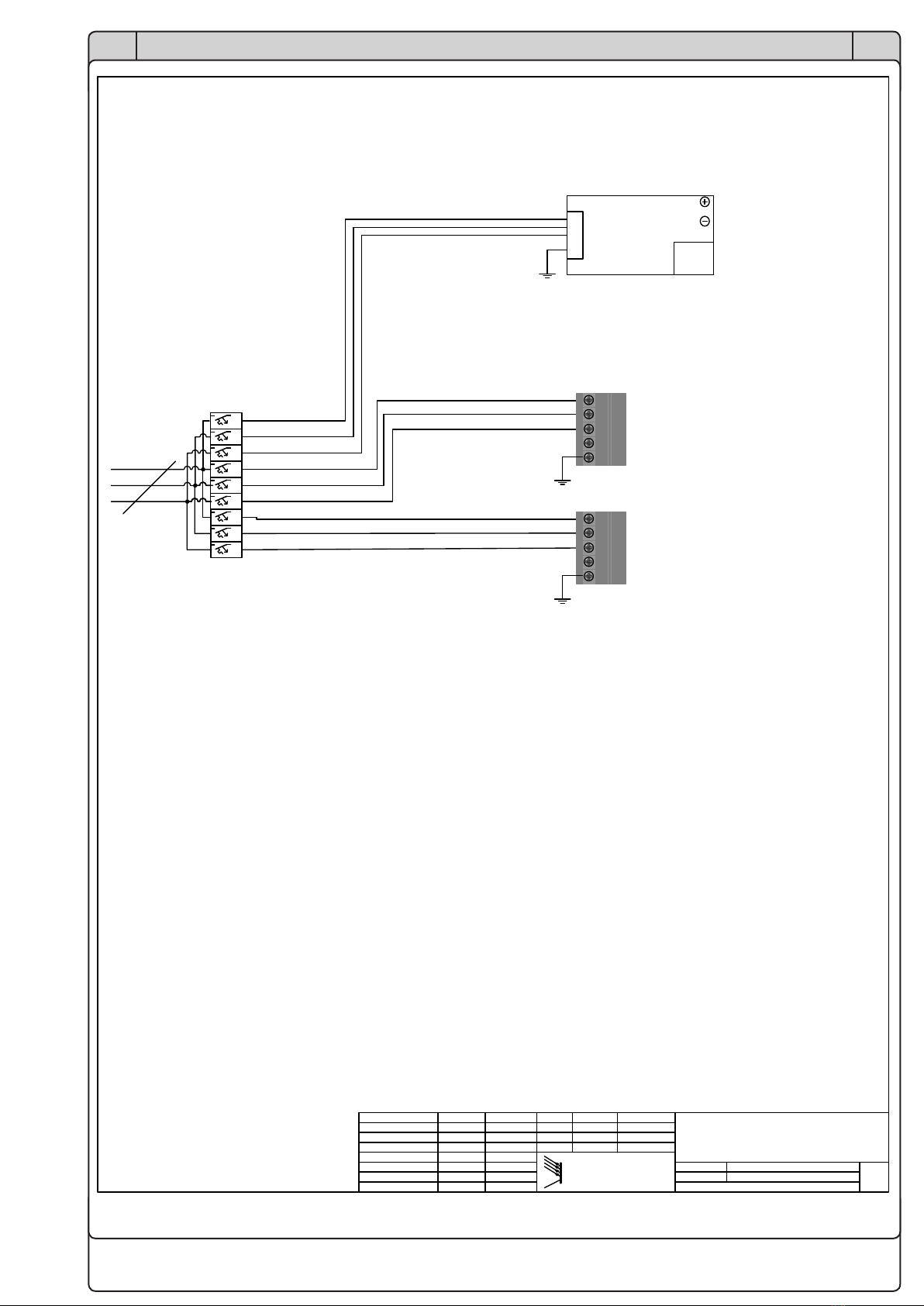
EN
Installationsanleitung / Installation guide
09114644
DE
Pa ge
2 vo n 2
E
AEA - Elektro Auto matik
EA--PSB Rack 15 HE für 1x
PSB 9080-360 3U , Not-Aus
Rev ‘d :
Created :
Da te Name
CAD System Microso ft Visio
ArtikelNr. : 09114644
File name :
Checked :
Da te NameChan ge notice
Füllgrabe
09114644_VP_02.vsd
04.09.2017
07.08.2017 Füllgrabe
20.09.2017 S ta b e r oc k
S te c kd o se , USB
F3...F1
X1
PSB 9080-360
Unit 1
L1/L2/L3/ PE
M / S
Sharebus +
-
L1
L2
L3
PE
32A32A32A32A32A32A
2L1
2L2
2L3
K amm sch ie ne 1
Comb rail
PS3/12
4L1 blk 6mm2
4L2 blk 6mm2
4L3 blk 6mm2
5L1 blk 6mm2
5L2 blk 6mm2
5L3 blk 6mm2
H07V-K
blk 16mm2
32A32A32A
6L3 blk 6mm2
6L1 blk 6mm2
6L2 blk 6mm2
L1 L2 L3 N PE
Unit 3
Gerät nicht bestückt
Unit not equipped
L1 L2 L3 N PE
Unit 2
Gerät nicht bestückt
Unit not equipped


EA-Elektro-Automatik GmbH & Co. KG
Entwicklung - Produktion - Vertrieb
Development - Production - Sales
Helmholtzstraße 31-37
41747 Viersen
Germany
Fon: 02162 / 37 85-0
Fax: 02162 / 16 230
Mail: [email protected]
Web: www.elektroautomatik.de
Other manuals for PSB Rack 15U
1
Table of contents
Other Elektro-Automatik UPS manuals

Elektro-Automatik
Elektro-Automatik Guard LCD 2 Series Operator's manual

Elektro-Automatik
Elektro-Automatik Guard LCD 2 Series User manual

Elektro-Automatik
Elektro-Automatik PSI Rack 24U User manual

Elektro-Automatik
Elektro-Automatik Informer Compact 1000 User manual

Elektro-Automatik
Elektro-Automatik PSB Rack 15U User manual


