Schuch nD8700 Series User manual

!
o
Operating Instructions
Explosion-proof
LED-Floodlight / plane surface floodlight
ExFOCO L
Series nD8700…
The safety of people and equipment in hazardous areas depends on the
observance of all safety standards. Exact knowledge of all applicable
regulations and standards is mandatory for installation, maintenance and
repair of explosion proof equipment, especially
the determinations of IEC/EN 60079-14 and IEC/EN 60079-17 for the
maintenance of explosion-proof appliances
the generally accepted rules of technology
the national health and safety standards
the safety instructions of these operating instructions
the characteristic data on the type plate and the instruction plates

10/2022•L-01424-4-14 2
1. Safety Instructions
Mounting and installation must be done in accordance with the respective regulations.
The light fitting must be protected against overvoltage, overcurrent, short circuits and other
electrical failures.
The light fitting must be operated in an undamaged condition only.
The light fitting may only be opened if it has been disconnected from the mains supply completely.
It is allowed to open the light fitting in a non-explosive (non hazardous) atmosphere only.
The non-stationary use of the light fitting as well as any other inappropriate usage is prohibited.
The operation of the light fitting is allowed within its assessment thresholds only.
In regard to the minimum and maximum admissible ambient temperature potential sources of cold
and heat (e.g. direct heat or solar radiation, cooling units) have to be considered.
If the light fitting is subject to a special application that is influenced chemically, mechanically,
thermically or electrically or if the light fitting will be subject to any kind of vibrations, it is highly
recommended to consult the Adolf Schuch GmbH before starting the installation.
Every structural modification will cause dangerous situations and consequently the certification of
this light fitting will be null and void.
The light fitting is not allowed to be installed in process areas where strong electrical fields
may occur (i.e. HV Sparkling Electrodes or Particle Streams). Reason is to avoid any
electrostatic charge of the light fitting itself.
The filling level of the connection cable should be quite high for avoiding any air penetrating the
inside of the light fitting through the cable.
The stated minimum distance between light fitting and illuminated objects must be observed.
Applying an explosion-proof breathing gland for pressure compensation is not allowed.
Replace damaged parts by original spare parts from the Adolf Schuch GmbH only.
The LED-modules of this light fitting must be replaced by A. Schuch GmbH, by a service technician
who is instructed from Schuch or by any other person with equivalent qualification only.
Special versions with seawater-resistant paintwork:
Caution - Risk of electrostatic discharge!
Fitting to be cleaned with damp cloth only!
In areas with risk of accidental electrostatic charge (e.g. by passing by) the light fitting must
be protected by appropriate measures.

10/2022•L-01424-4-14 3
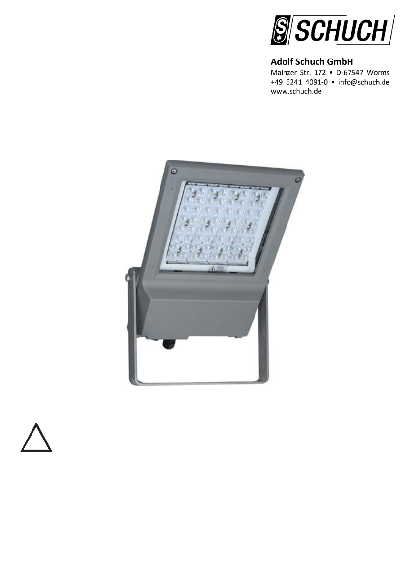
!
2. Operating Advice
Any application of the light fitting that is incorrect or even forbidden will lead to the fact that the
manufacturer's warranty is lost.
LED are sensitive electronic components. Please ensure that the LED are protected against
mechanical and electrostatic attacks whenever the light fitting is open. For this reason the LED
must not be touched either.
Due to harmful gases and other corrosive substances (e.g. ammoniac, sulphur- or chlorine
compounds) it may come to damages of the LEDs. Depending on the substance, the concentration,
the temperature and the dwell time, damages up to total black-out are possible. This may occur
also to fittings with high degree of protection. The suitability of the light fitting for the respective
application can only be checked by running a test at site.
Please note, that fittings of series nD8700 runs with LED modules of risk group 2. The luminaires
should be positioned so that prolonged staring into the luminaire at a distance closer than 1.08 m is
not expected.
Precautions must be taken to protect the light fitting against potential overvoltage caused by
lightning strikes.
The light fitting has an additional Ex cable gland, which is locked by a closing plug and which is
designed as a test port to run the test for restricted breathing (see section 5.3, Testing the
restricted breathing).
The Ex cable gland with closing plug, which is designed as a test port, must not
be used for cable entry!
The operation of this light fitting is only allowed if the Ex cable gland, which is
designed as a test port, is installed and locked with the provided closing plug!
Due to a high inrush current when switching on the light fitting, the number of light fittings which can
be connected to a single fused circuit is limited (Possible number of light fittings per circuit breaker
see section 3, Technical Data).
All DALI dimmable light fittings have two additional terminals marked „DA“. Lines to the control
terminals must be mains voltage proof.
Light fitting versions with the option of power reduction (nD8700 ... LR) are designed with an
additional connection terminal (Marking: LSt) for connecting the control phase.
In the standard setting, the light fitting delivers 100% luminous flux when the control phase is
pending (LSt = 230V). Without a control phase (LSt = 0V), the light fitting is dimmed to 50%. The
control phase does not have to be in phase with the supply (L).
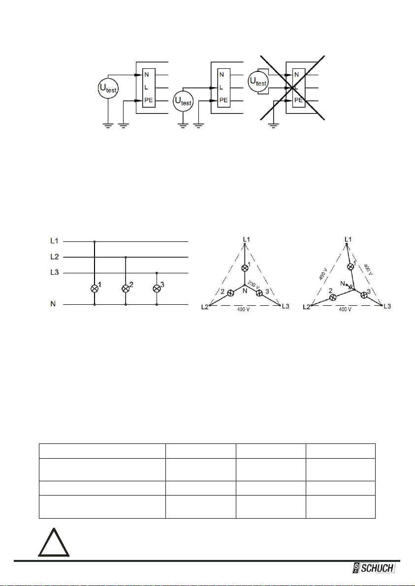
In case of versions for connection to group or central battery systems (ZB), the type of operation
(Stand-by operation = 0; Maintained operation = 1) must be permanently marked on the type plate
of the light fitting (see illustration).
Delivery status Stand-by operation Maintained operation
Z
*
****
Z
0
****
Z
1
****

10/2022•L-01424-4-14 4
3. Technical Data
Series: nD8700
Explosion-proof LED-Floodlight / plane surface floodlight for operating in
hazardous areas of zones 2 and 22.
Explosion protection: oII 3 G Ex nR IIC T4 Gc
oII 3 D Ex tc IIIC T100 °C Dc
Certification: SH 17.8700
Rated voltage: 220…240 V AC; 50/60 Hz
Special version nD8700 …ZB: 176…250 V DC in addition
Further special versions: see type plate
Isolation class: I
Ingress protection: IP66
Ambient temperature: -30 °C … +40 °C (Standard version)
Special versions for higher ambient temperatures see type plate
Energy efficiency class: This light fitting contains a light source of the energy efficiency class: C
Power consumption: The power consumption of the LED is dependent on production fluctuations
as well as on the service temperature.
This is why just reference values can be given as follows:
nD8700 4803: ca. 106 W
nD8700 6403: ca. 140 W
Special versions: see type plate
Cable entry: The built in Ex cable gland with thread size M20 x 1.5 only!
(spare-part-no. 90120 9000)
Sealing range: 8 - 13 mm
Torques: Connection thread 2.3 Nm; Pressing screw 1.5 Nm
(Ex cable gland with closing plug = Test port)
or an Ex cable gland with an equivalent flat seal approved by the
manufacturer or in accordance with national regulations for the types of
protection nR and tc.
See information label on the front page when having special versions!
Test port: Ex cable gland with closing plug (spare-part-no. 90122 9000)
Connection per terminal: Ampacity: 16 A max.
Clamping range: 2 x 0.75 - 2.5 mm² (solid core or stranded)
2 x 1.5 - 2.5 mm² (flexible)
Req. stripping length: 8 mm (conductor 0.75 - 1.0 mm²)
9 mm (conductor 1.5 - 2.5 mm²)
See information label on the front page when having special versions!
Possible number of
light fittings per circuit
breaker*:
*) Typical values; possible deviations depending on make, cable impedance and temperature
Information on special versions on request
Locking: 2 socket head cap screws (M6)
Minimum distance
to illuminated surface:
nD8700 …
Type
B 10 A
Type
B 16 A
Type
C 10 A
Type
C 16 A
4803
4
7
7
11
6403
4
7
7
11

10/2022•L-01424-4-14 5
!
Weight: ca. 9,6 kg
Wind load area: 0,15 m²
Dimensions:
(all measures in mm)
The retaining bracket must be fastened with two screws.
Only the two outer holes (distance: 170 mm) must be
used for this purpose!
Swivel range of
the retaining bracket:
Operation position:
Lighting downwards resp.
horizontally;
Light fitting is suitable for indoor
installation also;
The light fitting must be installed in
such a way that sufficient air
circulation is ensured for the heat
dissipation.

10/2022•L-01424-4-14 6
!
!
!
Equipotential bonding: Connection terminal for equipotential bonding on the outside of the light
fitting
Clamping range: 4 mm² max.
Torque of terminal screw: 2 Nm max.
Fuse: Miniature fuse 5x20 mm; T 3.15 A H; 250 V AC/DC; Type 179200;
Article-No. 90294 9002 (in versions nD8700 4803.. ZB and
nD8700 6403 ZB.. only)
4. Installation
The safety of this light fitting is only guaranteed as long as it is operated within its
assessment threshold. Installation and maintenance must be done in accordance with the
respective regulations!
The installation of explosion-proof light fittings must be done by Ex-skilled electricians
only!
In regard to the minimum and maximum admissible ambient temperature potential
sources of cold and heat (e.g. direct heat or solar radiation, cooling units) have to be
considered!
The application of this light fitting in an explosive dust atmosphere is depending on the
properties of the surrounding dust. Please ensure that there will be an adequate difference
between the maximum surface temperature of the fitting and the glowing and the ignition
temperature of the respective dust!
The light fitting must be mounted in the instructed operation position (see section 3,
Technical Data)!
The minimum distance to the illuminated surface must be observed (see section 3,
Technical Data)!
Applying an explosion-proof breathing gland for pressure compensation is not allowed!
4.1 How to open the light fitting
The light fitting may only be opened if it has been disconnected from the mains supply
completely!
It is allowed to open the light fitting in a non-explosive (non hazardous) atmosphere
only!
Please ensure that the LED are protected against mechanical and electrostatic attacks
whenever the light fitting is open. For this reason the LED must not be touched either!
Unscrew the two screws in the front part of the housing and open the light fitting.
4.2 Electrical connection
The filling level of the connection cable should be quite high for avoiding any air
penetrating the inside of the light fitting through the cable!
The test port for restricted breathing (Ex cable gland with closing plug, see
illustration in section 3, Technical Data), must not be used for cable entry in any
case!
After mounting the light fitting insert the connection cable through the Ex cable gland. An inlaid dust
protective disc, if existing, must be removed before.
Fasten the pressing screw of the Ex cable gland (Torque see section 3, Technical Data).

10/2022•L-01424-4-14 7
!
!
!
!
Outside the light fitting appropriate measures (e.g. pull relief clips) must be taken to
protect the connection cable from twist and it must be ensured that no tensile forces react
on the wiring and the Ex cable gland!
The diameter of the connection cable must correspond to the sealing range of the Ex
cable gland (see section 3, Technical Data)!
The conductors must not be damaged when skinning resp. stripping the cable!
When stripping the cable special attention needs to be paid to the correct length of the
conductor end sections (see section 3, Technical Data)!
Connect the conductors of the connection cable to the right terminals as per marking.
It is important to ensure that the bare conductor is fully inserted into the terminal and that
no cable insulation is clamped!
4.3 Replacing LED circuit boards and electronic gear
Replacement of the LED boards and/or of the electronic gear has been described in the separate
instructions which can be found attached to the spare parts to be supplied.
4.4 How to close the light fitting
Put the parts of the housing together and tighten the two screws in the front part of the housing.
The two screws must be tightened so far that the two housing parts are firmly on top of one another
in the sector of the screws.
After closing the light fitting please make sure that the gasket is correctly sealing it!
5. Commissioning
Before commissioning this explosion-proof lighting fitting please check and ensure that:
the light fitting has been installed according to the regulations and in the allowed operating position.
the Ex cable glands are securely fixed in the housing and the closing plug is installed in a proper
manner (Torques see section 3, Technical Data).
the pressing screw of every Ex cable gland is tightened with the required torque (Torques see
section 3, Technical Data).
the connection cable has been firmly installed and is not subject to any tension whatsoever.
the bare conductor is fully inserted into the terminal and that no cable insulation is clamped.
the light fitting is closed correctly.
all gaskets are effective.
the light fitting is not damaged whatsoever.
The restricted breathing of the light fitting is condition for its safe operation!
Therefore, prior to commissioning, check the restricted breathing in accordance with
section 5.3.

10/2022•L-01424-4-14 8
!
5.1 Isolation measurement
For measuring the isolating resistance the test voltage must be put on between the outer conductor
and the earth conductor or between the neutral conductor and the earth conductor only.
After finishing the isolation test the conductor between the mains and the light fitting must be
reconnected safely. Before starting operation the connection of the neutral conductor must be safe for
avoiding any damage whatsoever of the electronic control gear caused by any inadmissible excess-
voltage in case of an unbalanced mains load. (see section 5.2)
5.2 Electronic gear in 3-phase-operation
The diagram shows the wiring for light fittings or light fitting groups in 3-phase circuits and with a
common neutral conductor N. If the common neutral conductor is interrupted and voltage is present,
then light fittings or groups of light fittings may be exposed to unacceptably high voltages and
consequently the electronic gear may be destroyed.
Light fittings with electronic gear OK fault
5.3 Testing the restricted breathing
The test of the restricted breathing of the light fitting must be carried out after installation and at regular
intervals. For this purpose, the light fitting is provided with a test port, which consists of an Ex cable
gland which is locked by a closing plug.
For testing, a negative pressure is to be generated in the light fitting via the test port. Under constant
temperature conditions, the vacuum must exceed a predetermined minimum value after a specified
waiting time has elapsed.
According to EN/IEC 60079-15:2019, section 12.2.2.1.2, three test methods can be used:
Method 1
Method 2
Method 3
Underpressure
at the beginning of the test
3 kPa
(30 mbar)
0,3 kPa
(3 mbar)
0,3 kPa
(3 mbar)
Waiting time
14 s
14 s
90 s
Minimum underpressure
after waiting time has elapsed
2,7 kPa
(27 mbar)
0,27 kPa
(2,7 mbar)
0,15 kPa
(1,5 mbar)
After completing the test, make sure that the closing plug is inserted back into the Ex
cable gland and the pressing screw is tightened properly (Torque see section 3,
Technical Data).

10/2022•L-01424-4-14 9
!
!
!
6. Maintenance
6.1 Repair- and maintenance works
The light fitting may only be opened if it has been disconnected from the mains supply
completely!
It is allowed to open the light fitting in a non-explosive (non hazardous) atmosphere
only!
For applications in dusty atmospheres the light fitting must be cleaned before opening!
Ensure that no dust can get into the light fitting when it is open!
Working on the inner parts of the light fitting is allowed in non hazardous atmosphere
only!
Replace damaged parts by original spare parts from the Adolf Schuch GmbH only!
Spare Parts:
For spare parts inquiries, in addition to the complete type designation of the light fitting, the serial
number of the light fitting must be stated. The serial number is printed on the type plate of the light
fitting –on the bottom left.
If programmed electronic gear is required as a replacement, its
configuration no. printed on a label on the gear below the barcode
must also be indicated.
6.2 Cleaning the light fitting
If possible glass and housing of the light fitting shall be cleaned with water only. When
using any kind of cleaning agent make sure that there is no damaging influence at all
especially on the sealing material!
Pay attention to the following in case of application of this light fitting in dusty atmospheres:
Dust deposits show heat-insulating properties and thus reduce the service life of the light fitting. It is
necessary to clean the fitting from dust regularly. In case the dust layer may be higher than 5 mm it
must be ensured that the surface temperature of the light fitting does not exceed the maximum
permissible surface temperature of the specific dust considering the thickness of the dust layer. The
dust layer must not exceed 50 mm at any time.
6.3 Regular maintenance work
Follow the instructions of section 6.1!
Explosion-proof light fittings need regular maintenance according to the national rules of the country
they are installed. Especially components which are important for the Explosion Category have to be
carefully checked. Therefore it must to be checked very carefully:
glass, housing and gaskets for any kind of damages.
effectiveness of gasket between the two parts of the housing and between housing and glass.
the correct installation and tightness of Ex cable glands and closing plug (Torques see section 3,
Technical Data).
all parts of plastic inside the light fitting to attend to colour change, deformation and damaging.
the tight fit of the conductor and the condition of the cable insulation.

10/2022•L-01424-4-14 10
!
that the light fitting is closed correctly and the gasket is effective.
The restricted breathing of the light fitting is condition for its safe operation and must
therefore be regularly checked under particular consideration of its operating conditions
(see section 5.3, Testing the restricted breathing)!

10/2022•L-01424-4-14 11

10/2022•L-01424-4-14 12
The test certificates are ready to be loaded down from our homepage - www.schuch.de - or we shall send it
on request.
Misprints, modifications and errors are excepted
This manual suits for next models
1
Table of contents
Popular Floodlight manuals by other brands

brennenstuhl
brennenstuhl BLUMO 2000 A operating instructions

Philips Selecon
Philips Selecon RAMA LED Luminaires Installation & user manual

Wetelux
Wetelux CE-82-Y S.S 300 instruction manual

Francis Searchlights
Francis Searchlights A7195 VL500 150w 24v LED User instruction & installation manual

X4-Life
X4-Life 701408 instruction manual

Cooper Lighting
Cooper Lighting MQF150 instruction manual