Schulte-Schlagbaum Safe-O-Tronic User manual

INSTALLATION
SAFE-O-TRONIC
(1)
(2)
Fig. 1: SAFE-O-TRONIC layout right (layout left = mirror image)
(1) Recommended door hole diameter 23 mm
(2) max. door thickness 21.5 mm

SAG SAFE-O-TRONIC Installation
Schulte-Schlagbaum AG Page 2of 12 SOT-Manual.DOC
Copyright 1998 - 2003 by
Schulte-Schlagbaum AG
Nevigeser Straße 100
D-42553 Velbert
Tel.: +49 20512086155
With the edition of this document, all previous editions become void. Indications made in this manual may be
changed without previous notice.
Copying of this document, and giving it to others and the use or communication of the contents
thereof are forbidden without express authority. Offenders are liable to the payment of damages. All
rights are reserved in the event of the grant of a patent or the registration of a utility model or design.
Composition of the information in this document has been done to the best of our knowledge. Schulte-
Schlagbaum AG does not guarantee the correctness and completeness of the details given in this manual
and may not be held liable for damages ensuing from incorrect or incomplete information. Since, despite all
our efforts, errors may not be completely avoided, we are always grateful for your useful tips.
The instructions given in this manual are based on advantageous boundary conditions. Schulte-Schlagbaum
AG does not give any guarantee promise for perfect function in cross environments.
Schulte-Schlagbaum AG assumes no responsibility for the use of any information contained in this document
and makes no representation that they free of patent infringement. Schulte-Schlagbaum AG does not convey
any license under its patent rights nor the rights of others.

SAG SAFE-O-TRONIC Installation
Schulte-Schlagbaum AG Page 3of 12 SOT-Manual.DOC
Contents
1. Safety and warning notices – read before commissioning.......................................4
2. Basic functions of the SAFE-O-TRONIC.....................................................................5
2.1. Locking the SAFE-O-TRONIC..................................................................................5
2.2. Unlocking the SAFE-O-TRONIC ..............................................................................5
3. LED indicators ..............................................................................................................6
4. Installation.....................................................................................................................7
5. Commissioning.............................................................................................................7
5.1. Function testing with the "TestKey"..........................................................................7
5.2. Configuring the SAFE-O-TRONIC with the "SetupKey" ..........................................8
5.3. Resetting a SAFE-O-TRONIC with the "ResetKey".................................................9
5.4. Replacing a SAFE-O-TRONIC.................................................................................9
6. Battery .........................................................................................................................10
6.1. Battery replacement ...............................................................................................10
7. Service / Maintenance ................................................................................................10
8. Technical Data ............................................................................................................11
9. Approval ......................................................................................................................12
9.1. Europe (CE) ...........................................................................................................12
9.2. USA (FCC) .............................................................................................................12

SAG SAFE-O-TRONIC Installation
Schulte-Schlagbaum AG Page 4of 12 SOT-Manual.DOC
1. Safety and warning notices – read before commissioning
•The device may only be used for the purpose intended by the manufacturer.
•The operating instructions have to be handed out to every user and kept in an easily accessi-
ble place.
•Unacceptable changes as well as the use of spare parts and special features which are not
sold or recommended by the manufacturer, may cause fire, electric shocks and injuries.
Therefore, such measures lead to nonliability of the manufacturer and a lapse of all warranty
claims.
•The appliance is subject to the manufacturer’s guarantee regulations in the version valid at the
time of purchase. We cannot be held liable for improper or faulty manual or automatic adjust-
ment of parameters resp. improper use of the appliance.
•Repair work may only be carried out by the manufacturer.
•The user has to make sure that the appliance is installed and operated according to the tech-
nical rules of the country of installation as well as other regional regulations.

SAG SAFE-O-TRONIC Installation
Schulte-Schlagbaum AG Page 5of 12 SOT-Manual.DOC
2. Basic functions of the SAFE-O-TRONIC
(1) Rotary knob:
With integrated LED display (red / green) and antenna for exchange
between SAFE-O-TRONIC and megaKey.
(2) Battery compartment:
Use special screwdriver to open (Type: ID MS.SSD-A).
2.1. Locking the SAFE-O-TRONIC
1. Push rotary knob
SAFE-O-TRONIC is activated for 8 sec. (no indicator)
2. Present megaKey:
The green LED flashes for a max. of 8 sec. As long
as the green LED is flashing, the rotary knob can be
turned 90°and the SAFE-O-TRONIC locked.
3. Rotate knob 90°
Turning the knob locks the SAFE-O-TRONIC, which
acknowledges this by turning on the green LED for
several seconds.
2.2. Unlocking the SAFE-O-TRONIC
1. Push rotary knob
SAFE-O-TRONIC is activated for 8 sec. (no indicator)
2. Present megaKey:
As soon as a valid megaKey is recognized by the
SAFE-O-TRONIC the green LED begins to flash and
the rotary knob turns itself back to „unlocked“ position.

SAG SAFE-O-TRONIC Installation
Schulte-Schlagbaum AG Page 6of 12 SOT-Manual.DOC
3. LED indicators
¥(LED flashes green) OK
•Action was successfully completed (e.g. SAFE-O-TRONIC is locked or unlocked)
¥(LED flashes red) megaKey not authorized
Possible cause:
•Handling error (actuation sequence incorrect).
•Wrong SAFE-O-TRONIC (megaKey is not assigned to this SAFE-O-TRONIC or has already
locked another SAFE-O-TRONIC).
•Group number of SAFE-O-TRONIC and megaKey or MasterKey are different.
•megaKey does not belong to the system (wrong System IDs).
•Data on megaKey are incorrect or corrupt.
Possible remedies:
⇒Retry.
⇒Display the megalock number of the megaKey on the Infoterminal.
⇒Initialize megaKey for system.
⇒ReinitializemegaKey.
¥ó¥(LED flashes alternately red and green) Battery alarm
Possible cause:
•Battery voltage on the SAFE-O-TRONIC is too low (megalock can’t be locked).
Remedies:
⇒Block SAFE-O-TRONIC using MasterKey II.
⇒Replace battery immediately !
¥&¥(LED flashes red/green at same time)SAFE-O-TRONIC is blocked / wrong
megaKey
Possible cause:
•SAFE-O-TRONIC was unlocked (locked) with MasterKey I or blocked by MasterKey II.
•MasterKey Generation of MasterKey I or MasterKey II is wrong (old MasterKey).
•Operating mode of SAFE-O-TRONIC and megaKey do not agree
-SAFE-O-TRONIC for free cabinet select with fixed-megaKey or multi-megaKey
-SAFE-O-TRONIC for fixed cabinet assignment with free-megaKey or multi-megaKey
-SAFE-O-TRONIC in multi-user mode and free-megaKey or fixed-megaKey
•SAFE-O-TRONIC is not configured.
Possible remedies:
⇒Use MasterKey II to enable SAFE-O-TRONIC .
⇒Check megaKey.
⇒Use SetupKey to configure SAFE-O-TRONIC .
l&l(LEDs constant on red and green) internal fault
Possible cause:
•SAFE-O-TRONIC is defective.
Remedies:
1. Replace SAFE-O-TRONIC .

SAG SAFE-O-TRONIC Installation
Schulte-Schlagbaum AG Page 7of 12 SOT-Manual.DOC
4. Installation
Installing:
The electronic cabinet lock SAFE-O-TRONIC is attached on the inside of a cabinet door
using four screws.
Testing:After installing, check the function of the SAFE-O-TRONIC using the TestKey.
Applying the reference plate:
Stick the user reference plate only to a flat, grease- and dust-free surface.
Configuring:
Once the installation work is complete and all the locks tested, they are configured using
theSetupKey.
5. Commissioning
5.1. Function testing with the "TestKey"
Lock SAFE-O-TRONIC :
1. Activate SAFE-O-TRONIC (push rotary knob)
2. Hold TestKey directly in front of the rotary knob.
3. When the green LED flashes, turn knob 90°.
Unlock the SAFE-O-TRONIC :
1. Activate SAFE-O-TRONIC (push rotary knob)
2 Hold TestKey directly in front of the rotary knob.
3. SAFE-O-TRONIC unlocks itself.
NOTE:
The TestKey is used to test the function of factory-new or non-configured SAFE-O-
TRONIC . Once the SetupKey has been used to configure the SAFE-O-TRONIC for
the system, the SAFE-O-TRONIC can no longer be locked or unlocked using the
TestKey!

SAG SAFE-O-TRONIC Installation
Schulte-Schlagbaum AG Page 8of 12 SOT-Manual.DOC
5.2. Configuring the SAFE-O-TRONIC with the "SetupKey"
The SetupKey is used to configure the System-ID, the cabinet number, the operating mode and
the group number in the SAFE-O-TRONIC . Only than can the SAFE-O-TRONIC be used in the
system.
An already configured SAFE-O-TRONIC will no longer accept the SetupKey. To change the con-
figuration of a SAFE-O-TRONIC , the latter must first have been cleared using a valid ResetKey.
CAUTION:
Use only a SetupKey having the correct Group No. and System-ID.
Sequence:
1. Set the parameters on megalock Admin or on the megalock Programmer and program them
into the SetupKey.
Set the following data:
- Next SAFE-O-TRONIC number to be programmed (cabinet number)
- Operating mode (free cabinet select / fixed cabinet assignment / multi-user mode)
- Group No. to which the SAFE-O-TRONIC is to be assigned.
2. Go to the first SAFE-O-TRONIC with the SetupKey, waken up the lock and configure it by pre-
senting the SetupKey.
The SetupKey must be held in front of the rotary knob until the SAFE-O-TRONIC ac-
knowledges this by causing the green LED to flash.
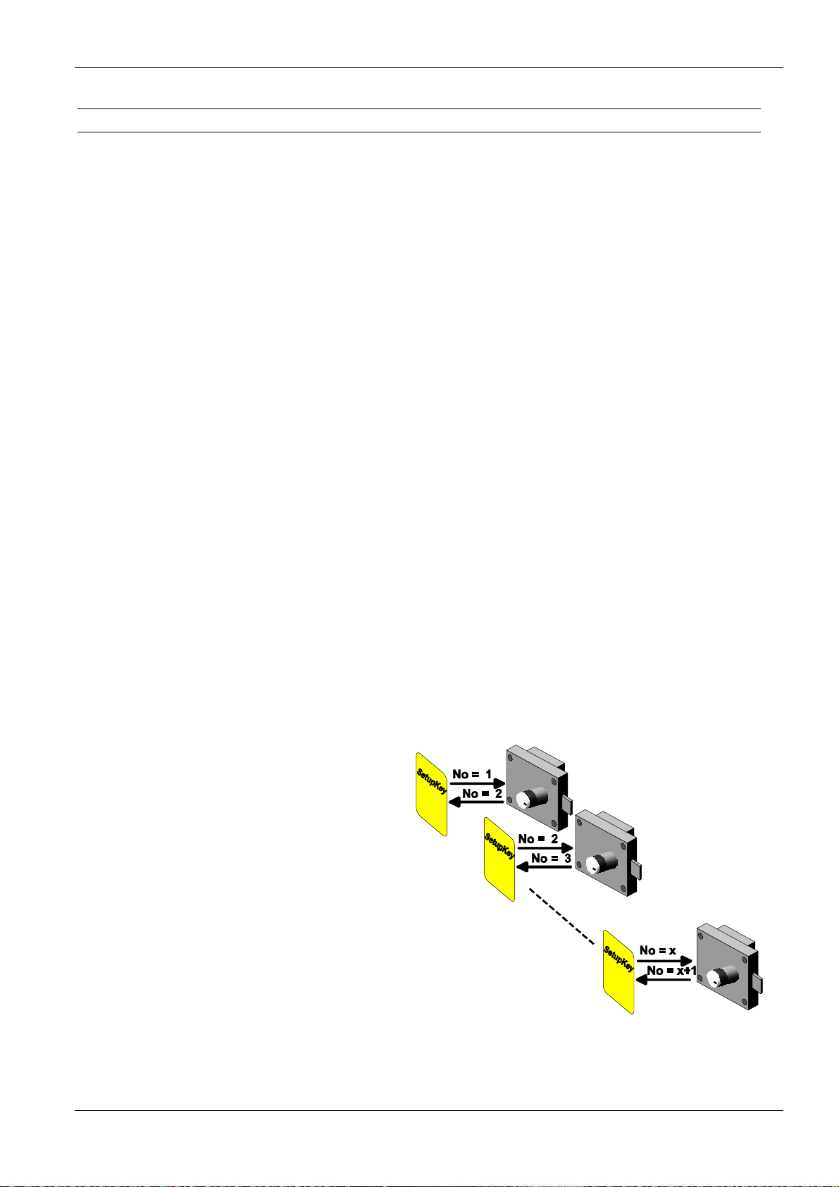
3. Now the next SAFE-O-TRONIC can be configured with a sequential cabinet number.
Assigning the megalock number is done according to the same principle.
Once the SAFE-O-TRONIC has uploaded
the number, it increments the number on the
SetupKey by +1.
Now the number for the next SAFE-O-
TRONIC is stored on the SetupKey, and as
many megalocks as desired can be initialized
with a sequential number without having to
first reprogram the SetupKey.
NOTE:
If a gap in the sequential numbering of the
SAFE-O-TRONIC s is desired, such as at
the end of a row of cabinets, the new
cabinet number will have to be pro-
grammed into the SetupKey.

SAG SAFE-O-TRONIC Installation
Schulte-Schlagbaum AG Page 9of 12 SOT-Manual.DOC
5.3. Resetting a SAFE-O-TRONIC with the "ResetKey"
Clearing a SAFE-O-TRONIC may be necessary for example if a mistake was made in initializing
(e.g. wrong cabinet number) or if a SAFE-O-TRONIC needs to have a different configuration.
NOTE
The ResetKey is only accepted by the SAFE-O-TRONIC if it is unlocked!
The megalock is reset in the following way:
1. Activate megalock (push rotary knob)
2. You have 8 seconds to hold the ResetKey in front of the rotary knob in the sensing zone
of the SAFE-O-TRONIC antenna.
Once the parameters in the SAFE-O-TRONIC have been cleared, the SAFE-O-TRONIC
acknowledges the process by causing the green LED to come on for a brief time followed
by simultaneous flashing of the green and red LED.
3. Now the SAFE-O-TRONIC can be reconfigured with a SetupKey
(see: 5.2. Configuring the SAFE-O-TRONIC with the "SetupKey").
5.4. Replacing a SAFE-O-TRONIC
If it becomes necessary to replace a SAFE-O-TRONIC , the new SAFE-O-TRONIC must first:
1. be configured with the megalock number and other parameters using the SetupKey
(see: 5.2. Configuring the SAFE-O-TRONIC with the "SetupKey") and
2. be actuated with a MasterKey to ensure that the new SAFE-O-TRONIC accepts only
MasterKeys having the currently valid MasterKey-Generation.

SAG SAFE-O-TRONIC Installation
Schulte-Schlagbaum AG Page 10 of 12 SOT-Manual.DOC
6. Battery
The battery in the SAFE-O-TRONIC is designed for at least 40 actuations daily within a period of
3 years. The time when the battery needs to be replaced will depend however on the self-
discharging of the battery and by climatic effects, especially cold temperatures.
To summarize, the time to replace the battery depends on the following factors:
1. the number of actuations,
2. how long the battery has been installed, and
3. the ambient temperature in which the SAFE-O-TRONIC is operated.
6.1. Battery replacement
The battery compartment integrated into the lock body is only accessible when the cabinet is
opened, and can only be opened using a special screwdriver (Type: ID ML.SSD-A).
•After opening the battery compartment, disconnect the discharged battery pack at the connec-
tor and plug in the new battery pack.
•Once the new battery pack has been installed, the SAFE-O-TRONIC is ready for immediate
use.
•The discharged battery pack must be properly disposed of according to prevailing envi-
ronmental regulations!
NOTE:
Use only batteries recommended by the manufacturer (Type: ID ML.BP-A). The use
of non-approved batteries may cause malfunctions and result in damage to the
SAFE-O-TRONIC .
7. Service / Maintenance
The mechanical parts of the SAFE-O-TRONIC are maintenance-free. Under no circum-
stances use mineral oil based lubricants or greases.
Clean only using non-sticky, non-residue cleaners and disinfectants. Do not use harsh sol-
vents, acids or lye for cleaning.

SAG SAFE-O-TRONIC Installation
Schulte-Schlagbaum AG Page 11 of 12 SOT-Manual.DOC
8. Technical Data
•Dimensions (W x H x D): 110 x 119 x 84 mm
•Weight: approx. 350 g (incl. battery)
•Enclosure rating IP 43
•Temperature range:
Operating:
Storage: 0 °C
-25 °C to
to 60 °C
60 °C
•Relative humidity
Function and storage: 10 % to 90 % (non-condensing)
•Battery life expectancy •3 years assuming 40 actuations daily
•Unlocking is possible for 6 weeks after reaching
battery alarm level
•Compatible
Transponder model HITAG
Transponder must be able to support “Advanced Mode“
•Indicators: •1 x LED red
•1 x LED green

SAG SAFE-O-TRONIC Installation
Schulte-Schlagbaum AG Page 12 of 12 SOT-Manual.DOC
9. Approval
9.1. Europe (CE)
When properly used this radio equipment conforms to the basic requirements of Article 3 and the
other relevant provisions of the R&TTE Directive 1999/5/E6 of March 99.
9.2. USA (FCC)
FCC ID: Q3ISOT01
This device complies with Part 15 of the FCC Rules. Operation is subject to the following
two conditions:
(1) this device may not cause harmful interference, and
(2) this device must accept any interference received, including interference that may
cause undesired operation.
Caution: Any changes or modifications not expressly approved by the party responsible
for compliance could void the user's authority to operate the equipment.
Table of contents
Popular Lock manuals by other brands

Theofils
Theofils KICCO S2 FIX 2 Operation instructions

Honeywell
Honeywell 8712009 Installation & operation guide

Allegion
Allegion Dexter DB1000 Deadbolt Standard Instructions for installation

Eaton
Eaton 1370 Series Technical data

Kensington
Kensington MicroSaver Instruction guide

GateKeyper
GateKeyper GKi-704 User instructions

Assa Abloy
Assa Abloy 8800 Series installation instructions

COMPX
COMPX Stock Locks C1975 Dimensional drawing

Winkhaus STV
Winkhaus STV AV2 operating manual

ARMAC MARTIN
ARMAC MARTIN Small Digbeth Latch instructions

BURG WATCHER
BURG WATCHER Tresor TRSE 6000 user manual

Paxton
Paxton PaxLock Pro Installation and commissioning guide