3
IMPORTANT INFORMATION AND SAFETY INSTRUCTIONS
PLEASE READ ALL INSTRUCTIONS CAREFULLY
When installing and using all electrical appliances, basic safety precautions should always be followed including the following:
ELECTRIC SHOCK HAZARD
To prevent electric shock, do not place cord, plugs or appliance in water or other liquid.
Do not operate any appliance with a damaged cord, plug, or after the appliance malfunctions.
If the supply cord is damaged, it must be replaced by the manufacturer, its service agent or similarly qualified persons in order to avoid a hazard.
Do not attempt to service this product. Repairs should be done by authorized service personnel.
Do not use outdoors or in damp areas.
FIRE HAZARD
When installing the appliance, allow a minimum airspace of 100mm around the back, sides, and top of the chiller unit for air circulation. Nothing should be placed in
front of the unit and there should be a 150mm air space in frontof the warm air outlet maintained at all times
PERSONAL INJURY
This appliance is not intended for use by persons (including children) with reduced physical, sensory or mental capabilities, or lack of experience and knowledge,
unless they have been given supervision or instruction concerning use of the appliance by a person responsible for their safety.
Children should be supervised to ensure that they do not play with the appliance.
This appliance is intended for use in household and similar applications, such as light commercial (up to 8 staff), the hospitality industry, and related residential type
environments.
INSTALLATION PRE-REQUIREMENTS
Power supply
A standard 10amp 3pin power outlet conveniently placed within 1m of the intended location of the boiler tank. This must be installed by a qualified electrician.
Water supply
A standard Cold water supply fitted with a 15mm stop tap situated within easy access of the intended location of the boiler tank. This must be installed by a qualified
plumber.
Supply water pressure must not exceed 1000kpa with pressure regulator installed.
Water supply must be microbiologically safe.
PROPERTY DAMAGE
In situations where any water leakage could result in damage to property, the complete Schwan Installation should be installed over a Drained Safe Tray,
plumbed to an appropriate drain.
DANGER
WARNING
WARNING
WARNING
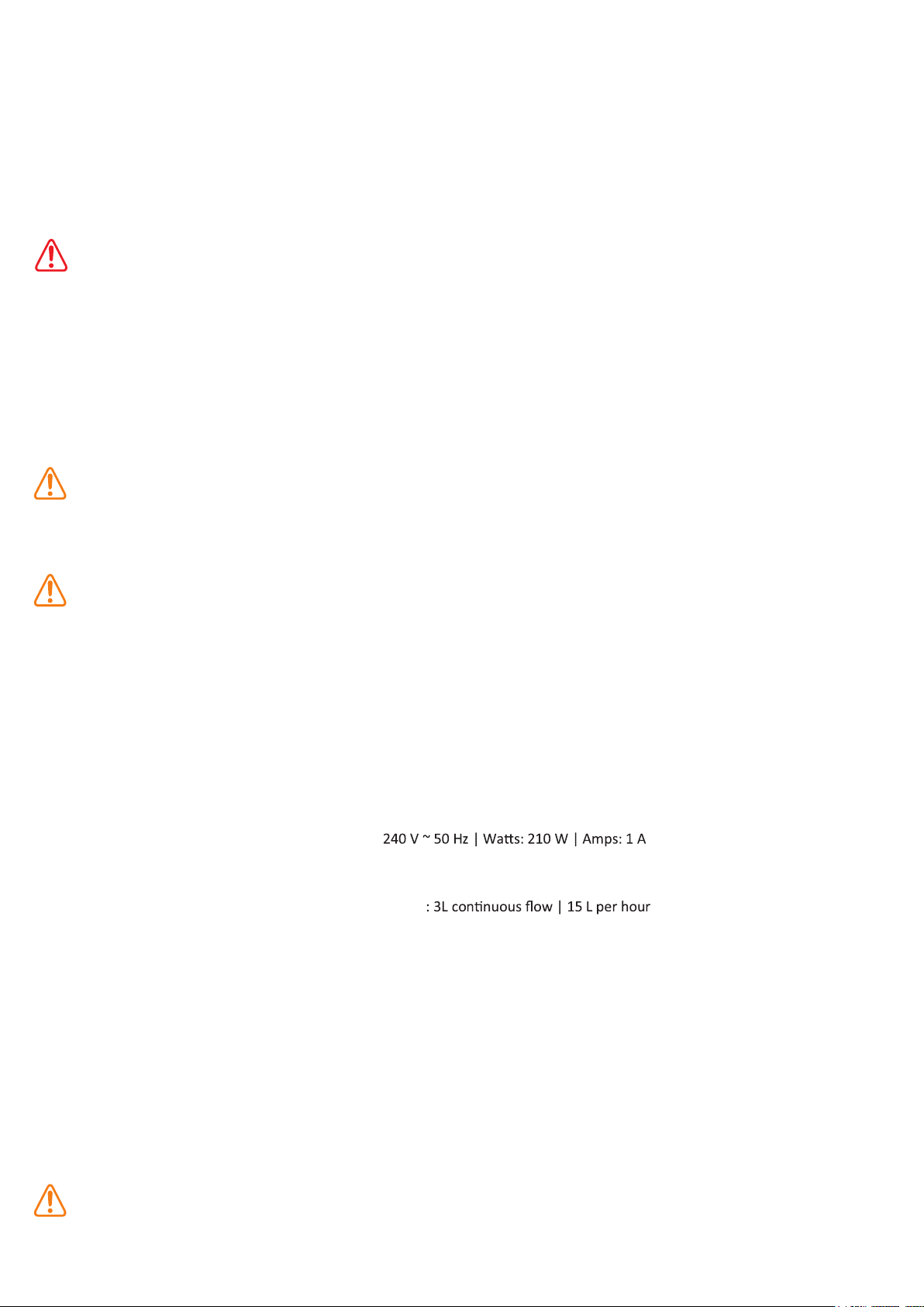
SPECIFICATIONS
Volts: 220-
Gas: Freon R134a Kg 0.100 Class N
Water supply pressure into chiller: MAX 300kpa | MIN 150kpa
Capacity at 3-10Co
Made in Italy
•
•
•
•
•
•
•
•
•
•
•
•
•
•