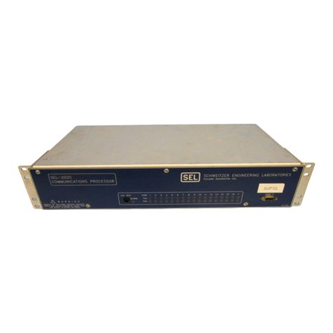
Schweitzer Engineering Laboratories SEL-2701 User manual

Schweitzer Engineering Laboratories
2350 NE Hopkins Court
Pullman, WA USA 99163-5603
Tel: (509) 332-1890 FAX: (509) 332-7990
SEL-2701
Ethernet Processor
Instruction Manual

CAUTION: Equipment components are sensitive to
electrostatic discharge (ESD). Undetectable permanent
damage can result if you do not use proper ESD procedures.
Ground yourself, your work surface, and this equipment before
removing any cover from this equipment. If your facility is not
equipped to work with these components, contact SEL about
returning this device and related SEL equipment for service.
!
DANGER: Disconnect or de-energize all external
connections before opening this device. Contact with
hazardous voltages and currents inside this device can cause
electrical shock resulting in injury or death.
!
ATTENTION: Les composants de cet équipement sont
sensibles aux décharges électrostatiques (DES). Des
dommages permanents non-décelables peuvent résulter de
l’absence de précautions contre les DES. Raccordez-vous
correctement à la terre, ainsi que la surface de travail et
l’appareil avant d’en retirer un panneau. Si vous n’êtes pas
équipés pour travailler avec ce type de composants, contacter
SEL afin de retourner l’appareil pour un service en usine.
!
DANGER: Débrancher tous les raccordements externes
avant d’ouvrir cet appareil. Tout contact avec des tensions
ou courants internes à l’appareil peut causer un choc
électrique pouvant entraîner des blessures ou la mort.
!
Schweitzer Engineering Laboratories, SELOGIC, Connectorized, , and Job Done are registered trademarks of
Schweitzer Engineering Laboratories. All brand or product names appearing in this document are the trademark or
registered trademark of their respective holders.
The software (firmware), schematic drawings, relay commands, and relay messages are copyright protected by the
United States Copyright Law and International Treaty provisions. All rights are reserved.
You may not copy, alter, disassemble, or reverse-engineer the software. You may not provide the software to any third
party.
The information in this manual is furnished for informational use only and is subject to change without notice. The
English language manual is the only approved SEL manual.
ã2001, 2002 Schweitzer Engineering Laboratories, Inc. All rights reserved.
This product is covered by the standard SEL 10-year warranty. For warranty details, visit www.selinc.com or contact
your customer service representative.

Date Code 20020501 SEL-2701 Ethernet Processor Instruction Manual
Table of Contents
List of Tables ........................................................................................................................................................ v
List of Figures.................................................................................................................................................... vii
Manual Change Information.......................................................................................................................... ix
Preface................................................................................................................................................................... xi
Section 1: Introduction
Introduction ..................................................................................................................................................... 1.1
Features............................................................................................................................................................ 1.2
Model Options ................................................................................................................................................. 1.3
Applications..................................................................................................................................................... 1.4
Ethernet Networks ......................................................................................................................................... 1.10
UCA2............................................................................................................................................................. 1.15
Specifications ................................................................................................................................................ 1.17
Section 2: Installation
Introduction ..................................................................................................................................................... 2.1
Installation ....................................................................................................................................................... 2.2
Initial Checkout ............................................................................................................................................... 2.4
Network Connections ...................................................................................................................................... 2.6
Section 3: Settings and Commands
Introduction ..................................................................................................................................................... 3.1
Ethernet Network Operation Settings.............................................................................................................. 3.2
Data Access Settings ....................................................................................................................................... 3.5
SEL-2701 Commands ................................................................................................................................... 3.10
Section 4: SEL-2030 Host
Introduction ..................................................................................................................................................... 4.1
Features and Capabilities................................................................................................................................. 4.2
Settings ............................................................................................................................................................ 4.3
Operation ......................................................................................................................................................... 4.5
Data Access ..................................................................................................................................................... 4.7
Section 5: SEL-400 Series Host
Introduction ..................................................................................................................................................... 5.1
Features and Capabilities................................................................................................................................. 5.2
Settings ............................................................................................................................................................ 5.3
Operation ......................................................................................................................................................... 5.4
Data Access ..................................................................................................................................................... 5.6
Section 6: Troubleshooting
Introduction ..................................................................................................................................................... 6.1
SEL-2701 Firmware IDs ................................................................................................................................. 6.2
SEL-2701 Indicator LEDs............................................................................................................................... 6.4
SEL-2701 Status.............................................................................................................................................. 6.5
Error Messages and Codes .............................................................................................................................. 6.6
Troubleshooting Procedures ............................................................................................................................ 6.7
Appendix A: Firmware Versions
Firmware Versions.......................................................................................................................................... A.1
SEL-2030........................................................................................................................................................ A.2
SEL-421 Relay ............................................................................................................................................... A.3

iv
SEL-2701 Ethernet Processor Instruction Manual Date Code 20020501
Table of Contents
Appendix B: UCA2 GOMSFE Models
Introduction..................................................................................................................................................... B.1
GOMSFE Tables ............................................................................................................................................. B.2
SEL-2030 Domains......................................................................................................................................... B.3
SEL-2030 Domain–LNO................................................................................................................................ B.4
SEL Relay Virtual Device............................................................................................................................... B.6
Communications Card or Non-SEL Virtual Device ..................................................................................... B.17
Special Translation Rules.............................................................................................................................. B.29
Appendix C: GOMSFE Model Example
Introduction..................................................................................................................................................... C.1
Settings............................................................................................................................................................ C.2
GOMSFE Models ........................................................................................................................................... C.4
Glossary........................................................................................................................................................... GL.1
Index ...................................................................................................................................................................IN.1

Date Code 20020501 SEL-2701 Ethernet Processor Instruction Manual
List of Tables
Section 1: Introduction
Table 1.1 SEL-2701 Network Connection Options ............................................................................... 1.3
Table 1.2 Ethernet Physical Layer Designators .....................................................................................1.3
Section 2: Installation
Section 3: Settings and Commands
Table 3.1 SEL-2701 Network Configuration Settings ........................................................................... 3.2
Table 3.2 DEFRTR Address Setting Examples...................................................................................... 3.3
Table 3.3 SEL-2701 IP Network Address Resolution Settings.............................................................. 3.4
Table 3.4 Basic File Structure ................................................................................................................ 3.5
Table 3.5 SEL-2701 FTP Settings.......................................................................................................... 3.6
Table 3.6 SEL-2701 Telnet Settings....................................................................................................... 3.7
Table 3.7 SEL-2701 UCA2 Settings ...................................................................................................... 3.8
Table 3.8 Control Characters................................................................................................................ 3.10
Table 3.9 SEL-2701 Command Summary ........................................................................................... 3.10
Table 3.10 SEL-2701 Access Levels ..................................................................................................... 3.11
Table 3.11 Access Level User Names and Passwords ........................................................................... 3.11
Table 3.12 DATE Command .................................................................................................................. 3.12
Table 3.13 GOOSE Command Variants.................................................................................................3.12
Table 3.14 GOOSE Sender IED Display Information ........................................................................... 3.13
Table 3.15 HELP Command Options..................................................................................................... 3.14
Table 3.16 ID Command Internal Parameters Displayed....................................................................... 3.14
Table 3.17 PING Command Options ..................................................................................................... 3.15
Table 3.18 TIME Command .................................................................................................................. 3.15
Section 4: SEL-2030 Host
Table 4.1 SEL-2030 Port Settings With SEL-2701 Installed................................................................. 4.3
Table 4.2 SEL-2030 Port Control Settings With SEL-2701 Installed.................................................... 4.3
Table 4.3 SEL-2030 Automatic Message Settings With SEL-2701 Installed........................................ 4.4
Table 4.4 SEL-2030 Access Levels ....................................................................................................... 4.5
Table 4.5 SEL-2030 Access Level User Names and Passwords............................................................ 4.5
Table 4.6 SEL-2030 LOCAL ELEMENTS2 ......................................................................................... 4.6
Table 4.7 SEL-2030 File Structure......................................................................................................... 4.7
Table 4.8 Example GLOBE Generic Binary Data Mapping................................................................ 4.11
Section 5: SEL-400 Series Host
Table 5.1 SEL-400 Series Relay Port Settings With SEL-2701 Installed.............................................. 5.3
Table 5.2 SEL-400 Series Relay Port Control Settings With SEL-2701 Installed ................................ 5.3
Table 5.3 SEL-400 Series Relay Access Levels .................................................................................... 5.4
Table 5.4 SEL-400 Series Relay Access Level User Names and Passwords......................................... 5.4
Table 5.5 SEL-400 Series Relay File Structure .....................................................................................5.6
Table 5.6 GOOSE Bit Pair Value Mapping............................................................................................5.7
Table 5.7 GLOBE MX Data................................................................................................................... 5.7
Section 6: Troubleshooting
Table 6.1 SEL-2701 LED Indicators...................................................................................................... 6.4
Table 6.2 Error Codes and Messages ..................................................................................................... 6.6
Table 6.3 Troubleshooting Procedures................................................................................................... 6.7
Appendix A: Firmware Versions
Table A.1 Firmware Versions................................................................................................................. A.1
Table A.2 SEL-2030 Firmware Compatibility....................................................................................... A.2
Table A.3 SEL-421 Relay Firmware Compatibility .............................................................................. A.3

vi List of Tables
SEL-2701 Ethernet Processor Instruction Manual Date Code 20020501
Appendix B: UCA2 GOMSFE Models
Table B.1 GOMSFE Model Table Column Definitions......................................................................... B.2
Table B.2 SEL-2030 Domains ............................................................................................................... B.3
Table B.3 Models in LN0 Domain ......................................................................................................... B.4
Table B.4 Device ID Model (DI)—SEL-2030....................................................................................... B.4
Table B.5 Globe Model (GLOBE)—SEL-2030..................................................................................... B.5
Table B.6 Models in Virtual Device Domain for SEL Relays ............................................................... B.6
Table B.7 Device ID Model (DI)—
SEL Relay Connected to an SEL-2030B.6
Table B.8 Fault Identification Model (FAULT)—
SEL Relay Connected to an SEL-2030B.7
Table B.9 Generic Control Model (GCTL)—SEL Relay Connected to an SEL-2030.......................... B.8
Table B.10 Globe Model (GLOBE)—SEL Relay Connected to an SEL-2030 ....................................... B.9
Table B.11 Polyphase Measurement Unit
Model (MMXU)—SEL Relay Connected to an SEL-2030B.10
Table B.12 Models in Virtual Device
Domain for Non-SEL IED Connected to an SEL-2030B.17
Table B.13 Device ID Model (DI)—Non-SEL IED Connected to an SEL-2030 .................................. B.17
Table B.14 Generic Control Model
(GCTL)—Non-SEL IED Connected to an SEL-2030B.18
Table B.15 Globe Model (GLOBE)—Non-SEL IED Connected to an SEL-2030................................ B.18
Table B.16 Polyphase Measurement Unit
Model (MMXU)—Non-SEL IED Connected to an SEL-2030B.19
Table B.17 Polyphase Meter Unit Model (MMTR)—
Non-SEL IED Connected to an SEL-2030B.25
Table B.18 Special Translation Rules .................................................................................................... B.29
Table B.19 Relay Target Bit Mapping.................................................................................................... B.30
Table B.20 Event Types ......................................................................................................................... B.30
Appendix C: GOMSFE Model Example
Table C.1 SEL-2030 Automatic Messaging Settings............................................................................. C.3
Table C.2 SEL-2701 Settings................................................................................................................. C.3

Date Code 20020501 SEL-2701 Ethernet Processor Instruction Manual
List of Figures
Section 1: Introduction
Figure 1.1 Redundant Substation Ethernet Network. .............................................................................. 1.4
Figure 1.2 Example Ethernet Substation Network. ................................................................................. 1.5
Figure 1.3 SEL Relays on Ethernet Network Using the SEL-2030. ....................................................... 1.7
Figure 1.4 Non-SEL EIA-232 IEDs on Ethernet Network Using the SEL-2030.................................... 1.8
Figure 1.5 OSI Seven-Layer Model....................................................................................................... 1.10
Figure 1.6 Adding a Node to a Multidrop Network. ............................................................................. 1.13
Figure 1.7 Ethernet Star Network.......................................................................................................... 1.13
Section 2: Installation
Figure 2.1 SEL-2030 ID Command......................................................................................................... 2.2
Figure 2.2 SEL-2030 WHO Command. ..................................................................................................2.4
Figure 2.3 SEL-2030 STATUS Command. ............................................................................................. 2.5
Figure 2.4 Two 10/100BASE-T Port Configuration................................................................................ 2.6
Figure 2.5 Two 10BASE-FL Port Configuration. ................................................................................... 2.6
Figure 2.6 Two 100BASE-FX Port Configuration.................................................................................. 2.6
Figure 2.7 10BASE-FL and 10/100BASE-T Port Configuration............................................................ 2.6
Figure 2.8 100BASE-FX and 10/100BASE-T Port Configuration. ........................................................ 2.7
Figure 2.9 100BASE-FX and 10BASE-FL Port Configuration. ............................................................. 2.7
Section 3: Settings and Commands
Figure 3.1 GOOSE Command Response............................................................................................... 3.13
Section 4: SEL-2030 Host
Section 5: SEL-400 Series Host
Section 6: Troubleshooting
Figure 6.1 Example SEL-2701 Panel. ..................................................................................................... 6.4
Appendix A: Firmware Versions
Appendix B: UCA2 GOMSFE Models
Appendix C: GOMSFE Model Example
Figure C.1 Example SEL-2030/SEL-351S Relay System. ......................................................................C.2
Figure C.2 GOMSFE Domains. ...............................................................................................................C.4
Figure C.3 GOMSFE Models Within DD04_FEEDER1 Domain...........................................................C.4
Figure C.4 DI Model. ...............................................................................................................................C.5
Figure C.5 FAULT Model. .......................................................................................................................C.5
Figure C.6 GCTL Model With RB3 ST (status) Point.............................................................................C.5
Figure C.7 MMXU Brick. ........................................................................................................................C.6

This page intentionally left blank

Date Code 20020501 SEL-2701 Ethernet Processor Instruction Manual
Manual Change Information
The date code at the bottom of each page of this manual reflects the creation or revision date. Date codes are
changed only on pages that have been revised and any following pages affected by the revisions (i.e., pagination).
If significant revisions are made to a section, the date code on all pages of the section will be changed to reflect the
revision date.
Each time revisions are made, both the main table of contents and the affected individual section table of contents
are regenerated and the date code is changed to reflect the revision date.
Changes in this manual to date are summarized below (most recent revisions listed at top).
Release Date Summary of Changes in this Release
This Manual Change Information section is provided as a record of changes made to this manual since the initial release.
20020501 Appendix A: Firmware Versions—Updated for new SEL-2701 release.
Appendix B: UCA2 GOMSFE Models—All UCA2 control points were made readable. Default data was set for
the UCA2 FAULT model.
20010719 Reissued entire manual to reflect the following changes:
Section 3: Settings and Commands—Updated default value of SUBNETM setting (Table 3.1 on page 3.2), added
additional discussion of Network Configuration on page 3.2, and corrected range for Telnet port settings
(Table 3.6 on page 3.7), added information on ENTXGOS setting (Table 3.7 on page 3.8).
Section 4: SEL-2030 Host—Revised Table 4.5 on page 4.5, added port parameter to description of SEL-2030
port command in Telnet From the SEL-2701 on page 4.7. Added discussion of outgoing GOOSE timing issues on
page 4.9.
Section 6: Troubleshooting—Correction, changed error code bit 8 to “Reserved for future use” in Table 6.2 on
page 6.6.
Appendix A: Firmware Versions—Updated for new SEL-2701 release.
20010425 Reissued entire manual to reflect the following changes:
Section 2: Installation—Clarification
Section 3: Settings and Commands—Corrected GOOSE sender detection logic
Appendix A: Firmware Versions—Change to SELBOOT Firmware Version only
Appendix B: UCA2 GOMSFE Models—Clarification
20010302 Initial Release

This page intentionally left blank

Date Code 20020501 SEL-2701 Ethernet Processor Instruction Manual
Preface
This instruction manual describes applications for an SEL-2701 Ethernet
Processor installed in SEL hosts including an SEL-2030 Communications
Processor. Main topics include the following:
➤Installing the SEL-2701
➤Accessing SEL-2701 settings
➤Operating the SEL-2701
➤Accessing data in a host with FTP, Telnet, and UCA2
The following list contains other references with additional information about
specific topics in this manual:
➤SEL-2030 User’s Guide
➤SEL-2030 Reference Manual
➤IEEE TR 1550–Technical Report UCA2 Draft Specifications
➤IEC 61850 CD UCA2 Object Modeling Specifications

xii
SEL-2701 Ethernet Processor Instruction Manual Date Code 20020501
Preface
Manual Overview
You probably will not need to review the entire manual to perform the specific
tasks that are your responsibility. The following is an overview of the sections
in this instruction manual:
Preface
.Describes how this manual is organized and conventions used in
this manual.
Section 1: Introduction
.Provides an overview of Ethernet networking and
a description of the SEL-2701.
Section 2: Installation
.Describes how to install the SEL-2701 in various
SEL hosts.
Section 3: Settings and Commands
.Describes SEL-2701 operation and
configuration.
Section 4: SEL-2030 Host
.Provides detailed information on how to use the
SEL-2701 within the SEL-2030.
Section 5: SEL-400 Series Host
.Provides detailed information on how to
use the SEL-2701 within the SEL-400 series relays.
Section 6: Troubleshooting
.Describes techniques for testing and
troubleshooting SEL-2701 installations.
Appendix A: Firmware Versions
.Lists the firmware versions applicable to
this manual.
Appendix B: UCA2 GOMSFE Models
.Lists rules for how the SEL-2701
populates the UCA2 GOMSFE application layer maps.
Appendix C: GOMSFE Model Example
.Illustrates how the SEL-2701
populates the GOMSFE models for an SEL-351S Relay connected to
an SEL-2030.

xiii
Date Code 20020501 SEL-2701 Ethernet Processor Instruction Manual
Preface
Conventions
Numbers This manual generally displays numbers as decimal values. Hexadecimal
numbers include the letter “h” appended to the number. For instance, 11 is the
decimal number eleven, but 11h is the hexadecimal number eleven, which
equals the decimal value 17.
Typographic
Conventions
IP Addresses Enter Internet Protocol (IP) addresses as a series of four values separated by
periods (e.g., 199.92.34.109). IP addresses are in the form
octet1.octet2.octet3.octet4, where each octet is a value from 0 to 255 in one of
the formats shown in the following table.
Settings You can set several SEL-2701 and other SEL device settings to NA. NA is a
special value that turns off or disables the setting.
Typographic Conventions
Example Description
STATUS Commands you type appear in bold/uppercase.
ENTER Single keystroke command.
CTRL + D Multiple keystroke command.
SEL-2701 Ethernet Processor Command responses.
Octet Entry Formats
Format Description Example
yyy Decimal 163
0xnn C style hexadecimal 0xA3
nnh SEL style hexadecimal A3h

This page intentionally left blank

Date Code 20020501 SEL-2701 Ethernet Processor Instruction Manual
Section 1
Introduction
Introduction
This section introduces the SEL-2701 Ethernet Processor and provides
information on the following topics:
➤Features
➤Model Options
➤Applications
➤Ethernet Networks
➤UCA2
➤Specifications

1.2
SEL-2701 Ethernet Processor Instruction Manual Date Code 20020501
Introduction
Features
Features
The SEL-2701 is an Ethernet processor card designed for use in SEL hosts
including the SEL-2030 Communications Processor and SEL-400 series
relays. The SEL-2701 provides the following features:
➤Powerful processor
➤Extended temperature rating
➤Ethernet network connection
➢Twisted-pair cable
➢Fiber-optic cable
➢Redundant physical interfaces
➤Support for TCP/IP protocol suite
➢FTP (File Transfer Protocol)
➢Telnet
➤UCA2 for Field Devices
➢OSI and TCP/IP protocol stacks
➢GOMSFE models
➢GOOSE messages
The SEL-2701 is a complete communication processing system with a
processor, memory, interface to the host, and Ethernet physical interface. The
host and processor card architecture uses the SEL-2701 for all network tasks.
The effect of isolating the host processor from communication processing is
that network activity does not degrade protection. You can also upgrade or
replace the SEL-2701 without disturbing settings or firmware in the host.
The operating temperature range of the SEL-2701 (–40° to +70°C) surpasses
that of standard office-grade Ethernet network equipment. The combination of
operating temperature range and additional environmental hardening,
described in Specifications on page 1.17, prepares the SEL-2701 for operation
in the harsh environment of substation control houses.
You can connect an SEL-2701 to several different Ethernet media. Use fiber-
optic cable to electrically isolate devices and provide a medium immune to
most electrical and magnetic interference. Use twisted-pair cable to reduce
installation cost where electrical isolation and noise concerns have been
addressed in other ways. The SEL-2701 twisted-pair interface is significantly
more robust than typical office-grade equipment protecting both the Ethernet
processor and its host.
The TCP/IP (Transmission Control Protocol/Internet Protocol) protocol suite
is one of the most recognized protocol suites (stack plus application protocols)
used on Ethernet networks because it is part of the Internet. The SEL-2701
supports the TCP/IP protocol stack. It also supports the TCP/IP application
layer protocols, FTP and Telnet.
The SEL-2701 provides a UCA2 (Utility Communication Architecture 2.0)
for Field Devices interface for SEL hosts. It also supports the OSI (Open
System Interconnect) and TCP/IP protocol stacks for UCA2 operations. The
SEL-2701 supports GOMSFE models and GOOSE peer-to-peer messaging.

1.3
Date Code 20020501 SEL-2701 Ethernet Processor Instruction Manual
Introduction
Model Options
Model Options
The SEL-2701 is available in several configurations. Each configuration
reflects a different combination of Ethernet physical interfaces. You can install
an SEL-2701 in any SEL host with a card slot. Please refer to Appendix A:
Firmware Versions for a list of compatible host and card firmware versions.
Order the SEL-2701 Ethernet Processors factory-installed in SEL hosts or
individually for field installation or spares. The SEL-2701 Ethernet physical
layer configuration is indicated by an option code in the part number as shown
in Tabl e 1.1.
The network port standard terms and corresponding network speeds and
media are listed in Table 1.2.
See the Model Option Table for the SEL-2701 and your host for complete part
number and ordering option information. You can obtain a Model Option
Table by contacting SEL through our web site at www.selinc.com or through
your local SEL representative.
Table 1.1 SEL-2701 Network Connection Options
Network
Connection Option Network Port A Network Port B
0 10/100BASE-T 10/100BASE-T
1 10BASE-FL 10BASE-FL
2 100BASE-FX 100BASE-FX
3 10/100BASE-T 10BASE-FL
4 10/100BASE-T 100BASE-FX
5 10BASE-FL 100BASE-FX
Table 1.2 Ethernet Physical Layer Designators
Identifier Media Speed
10/100BASE-T Twisted-pair with RJ-45
connector
10 or 100 Mbps
10BASE-FL Fiber-optic cable with ST
connectors
10 Mbps
100BASE-FX Fiber-optic cable with ST
connectors
100 Mbps

1.4
SEL-2701 Ethernet Processor Instruction Manual Date Code 20020501
Introduction
Applications
Applications
The SEL-2701 can assist with many substation networking applications. A
sampling of applications is listed below to help give you ideas on how to apply
the features of the SEL-2701.
Application Features Each SEL-2701 application contains a combination of major features. The
following paragraphs summarize the major features that you can combine in
your application.
Redundant Networks
Use the SEL-2701 to connect SEL hosts to redundant Ethernet networks. An
example redundant network connection is shown in Figure 1.1. The
SEL-2701 has two network ports that allow you to connect both the primary
network and the standby network to the SEL-2701. You do not have to install
two separate SEL-2701s to support a redundant network system. The benefit
of this arrangement is lower equipment and setup cost because there is only
one network card and one set of network settings per host.
Figure 1.1 Redundant Substation Ethernet Network.
When the SEL-2701 is unable to detect normal operation on the primary
network, it automatically switches from the primary network to the standby
network. The SEL-2701 returns to the primary network when normal
operation on the primary network resumes.
To Rem ote
Networks
Primary Network Standby Network
SEL Host
Router Router
SEL-2701
Switch Switch
WAN
Access Device

1.5
Date Code 20020501 SEL-2701 Ethernet Processor Instruction Manual
Introduction
Applications
Terminal Access
Use the SEL-2701 to provide terminal access over an Ethernet network to SEL
hosts and IEDs (Intelligent Electronic Devices) connected to SEL hosts that
incorporate an SEL-2701. Similar to connecting a PC (personal computer)
with terminal software to the front port of the host, you can use Telnet to
connect to the user interface of the host. The computer connecting to the SEL
host can be on the substation LAN (Local Area Network) or a remote LAN
with a WAN (Wide Area Network) connection to the substation LAN.
Many PC operating systems include a free Telnet application. Telnet
applications operate similarly to serial terminal applications. With a Telnet
application, you must specify an IP address and port number rather than a
serial port and baud rate to establish a Telnet session with the remote device.
After you start a Telnet session, your Telnet software operates as a terminal
program passing your keystrokes across the Ethernet network and displaying
responses.
If you have a network with the topology shown in Figure 1.2, you can
establish a direct Telnet connection from the Engineering Workstation to the
SEL-2701 in the SEL-2030, the SEL-2030, or the SEL-400 series relay. You
can also use the SEL-2030 transparent connection to reach the SEL relays and
IEDs connected to SEL-2030 serial ports. In this arrangement, the Telnet
application allows you to operate the user interface of the selected device
similarly to a direct serial connection.
Figure 1.2 Example Ethernet Substation Network.
Engineering
Workstation
SEL-2701
SEL-400 Series Relay
SEL-2701
Hub
SEL Relay
SEL Relay Non-SEL IED
SEL Relay
SEL-2030
Communications Processor
EIA-232
Ethernet

1.6
SEL-2701 Ethernet Processor Instruction Manual Date Code 20020501
Introduction
Applications
File Exchange
Use the SEL-2701 to exchange files with SEL hosts across an Ethernet
network. The SEL-2701 provides FTP access to files in the SEL host. You can
use a PC to collect event reports, sequential events recorder (SER) reports,
settings, and snapshots of metering data.
As with Telnet, there are free FTP applications included with several
operating systems and web browsers. Start the FTP application, log in, and use
point and click operations to exchange files with SEL hosts.
UCA2 Networking
Use the SEL-2701 to provide UCA2 connectivity to SEL hosts including the
SEL-2030 and SEL-400 series relays. Data in the host are presented in
GOMSFE models. In an SEL-400 series relay, the SEL-2701 automatically
populates GOMSFE models with relay measurements and other data. For
IEDs connected to the SEL-2030, you must configure the SEL-2030 to collect
data. Then the SEL-2701 automatically populates GOMSFE models with the
available data.
GOOSE peer-to-peer messaging is part of the GOMSFE model called
GLOBE. GOOSE is used for peer-to-peer control and protection messages.
The SEL-2701 generates outgoing GOOSE messages based on information in
the host. The SEL-2701 also monitors incoming GOOSE messages and passes
selected information to the host. If your host is an SEL-2030, the GOOSE
messages can be used to transmit information from and pass controls to the
connected IEDs.
Application
Examples
Networking for Installed SEL Relays Without Card Slots
By adding an SEL-2701 installed in an SEL-2030 to your design or adding an
SEL-2701 to your existing SEL-2030 as shown in Figure 1.3 on page 1.7, you
can quickly and inexpensively gain the advantages of Ethernet and UCA2
network connectivity:
➤Use Telnet for engineering connections to the SEL-2030 and
connected relays.
➤Use FTP to collect snapshots of data regions in the SEL-2030
with FTP file exchange.
➤Use UCA2 master devices to collect data from the SEL-2030
and connected relays.
➤Use GOOSE to exchange control data between relays
connected to the SEL-2030 and other UCA2 IEDs.
Table of contents
Other Schweitzer Engineering Laboratories Computer Hardware manuals