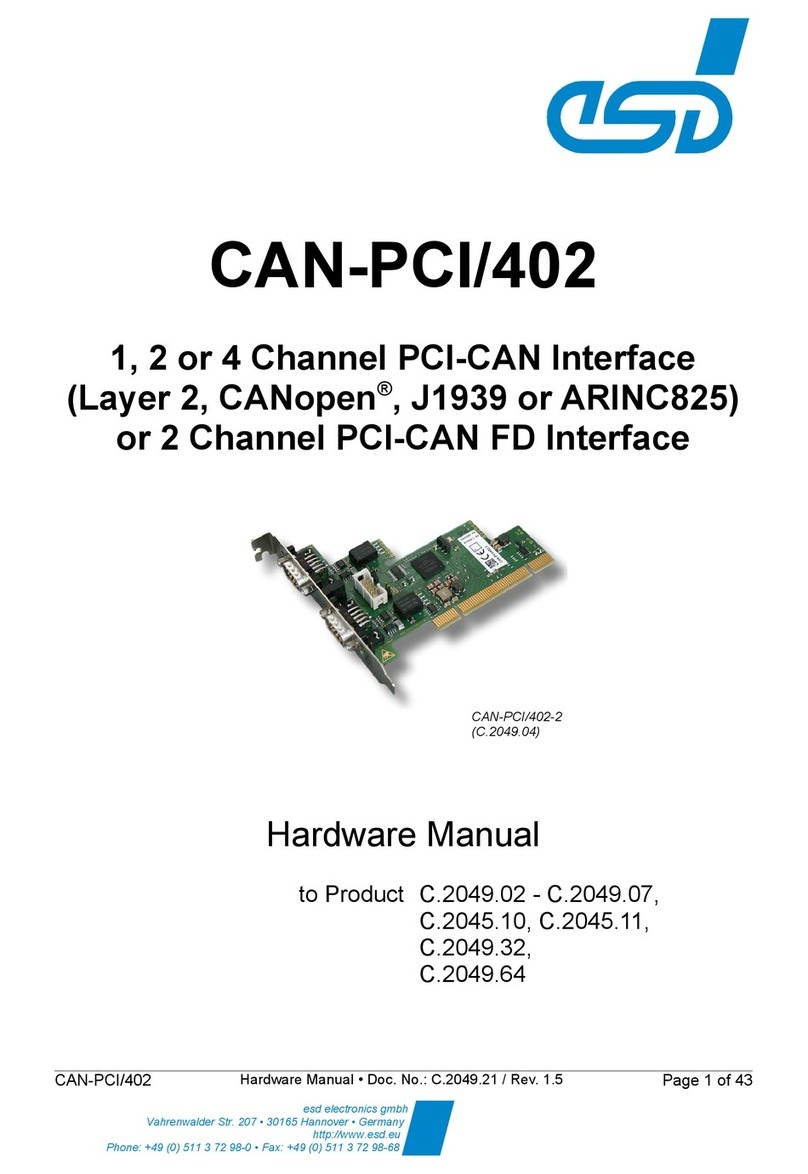
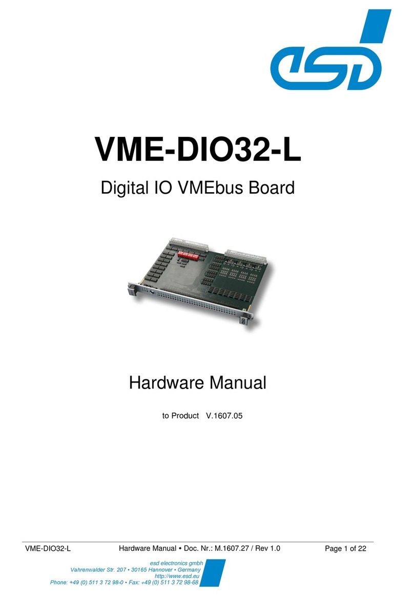
ESD VME-DIO32-C User manual

VME-DIO32-C / VME-DIO32 -F
Hardware Manual Doc. Nr.: M.1607.26 / Rev 1.0
Page 1 of 24
VME-DIO32-C
VME-DIO32-F
Digital IO VMEbus Board
Hardware Manual
to Products V.1607.06
K.0508.68

Page 2 of 24
Hardware Manual Doc. Nr.: M.1607.26 / Rev. 1.0
VME-DIO32-C / VME-DIO32-F
This manual contains important information and instructions on safe and efficient
handling of the VME-DIO32. Carefully read this manual before commencing any work
and follow the instructions.
The manual is a product component, please retain it for future use.
Trademark Notices
All trademarks, product names, company names or company logos used in this manual are reserved by their respective
owners.
Notes
The information in this document has been carefully checked and is believed to be entirely reliable.
esd electronics makes no warranty of any kind with regard to the material in this document and
assumes no responsibility for any errors that may appear in this document. In particular descriptions
and technical data specified in this document may not be constituted to be guaranteed product
features in any legal sense.
esd electronics reserves the right to make changes without notice to this, or any of its products, to
improve reliability, performance or design.
All rights to this documentation are reserved by esd electronics. Distribution to third parties, and
reproduction of this document in any form, whole or in part, are subject to esd electronics' written
approval.
© 2021 esd electronics gmbh, Hannover
esd electronics gmbh
Vahrenwalder Str. 207
30165 Hannover
Germany
Tel.:
+49-511-37298-0
Fax:
+49-511-37298-68
E-Mail:
Internet:
www.esd.eu

VME-DIO32-C / VME-DIO32-F
Hardware Manual Doc. Nr.: M.1607.26 / Rev. 1.0
Page 3 of 24
Document Information
Document file:
I:\Texte\Doku\MANUALS\VME\VME-DIO32-C_-F\Englisch\VME-DIO32-C_-F_Hardware-
Manual_en_10.docx
Date of print:
2021-08-03
Document-type
number:
DOC0800
Hardware version.:
1.0
Document History
The changes in the document listed below affect changes in the hardware as well as changes in the
description of the facts, only.
Rev.
Chapter
Changes versus previous version
Date
1.0
-
First English manual for VME-DIO32-C and VME-DIO32-F
2021-08-03
Technical details are subject to change without further notice.

Page 4 of 24
Hardware Manual Doc. Nr.: M.1607.26 / Rev. 1.0
VME-DIO32-C / VME-DIO32-F
Classification of Warning Messages and Safety Instructions
This manual contains noticeable descriptions, warning messages and safety instructions, which you
must follow to avoid personal injuries or death and property damage.
This is the safety alert symbol.
It is used to alert you to potential personal injury hazards. Obey all safety messages
and instructions that follow this symbol to avoid possible injury or death.
DANGER, WARNING, CAUTION
Depending on the hazard level the signal words DANGER, WARNING or CAUTION are used to
highlight safety instructions and warning messages. These messages may also include a warning
relating to property damage.
DANGER
Danger statements indicate a hazardous situation which, if not avoided, will result in
death or serious injury.
WARNING.
Warning statements indicate a hazardous situation that, if not avoided, could result in
death or serious injury.
CAUTION
Caution statements indicate a hazardous situation that, if not avoided, could result in
minor or moderate injury.
NOTICE
Notice statements are used to notify people on hazards that could result in things other than personal
injury, like property damage.
NOTICE
This NOTICE statement indicates that the device contains components sensitive to
electrostatic discharge.
NOTICE
This NOTICE statement contains the general mandatory sign and gives information that
must be heeded and complied with for a safe use.
INFORMATION
INFORMATION
Notes to point out something important or useful.

VME-DIO32-C / VME-DIO32-F
Hardware Manual Doc. Nr.: M.1607.26 / Rev. 1.0
Page 5 of 24
Safety Instructions
●
When working with the VME-DIO32 follow the instructions below and read the manual carefully
to protect yourself from injury and the VME-DIO32 from damage.
●
The device is a built-in component. It is essential to ensure that the device is mounted in a way
that cannot lead to endangering or injury of persons or damage to objects.
●
Do not use damaged or defective cables to connect the VME-DIO32 and follow the CAN wiring
hints in chapter: "Correct Wiring of Electrically Isolated CAN Networks".
●
In case of damages to the device, which might affect safety, appropriate and immediate
measures must be taken, that exclude an endangerment of persons and domestic animals and
property.
●
Current circuits which are connected to the device must be sufficiently protected against
hazardous voltage (SELV according to EN 60950-1).
●
The VME-DIO32 may only be driven by power supply current circuits, that are contact protected.
A power supply, that provides a safety extra-low voltage (SELV) according to EN 60950-1,
complies with these conditions.
●
The device must be securely installed in the control cabinet before commissioning.
●
Protect the VME-DIO32 from dust, moisture, and steam.
●
Protect the VME-DIO32 from shocks and vibrations.
●
The VME-DIO32 may become warm during normal use. Always allow adequate ventilation
around the VME-DIO32 and use care when handling.
●
Do not operate the VME-DIO32 adjacent to heat sources and do not expose it to unnecessary
thermal radiation. Ensure an ambient temperature as specified in the technical data.
DANGER
Hazardous Voltage - Risk of electric shock due to unintentional contact with uninsulated
live parts with high voltages inside of the system into which the VME-DIO32 is to be
integrated.
→Disconnect all hazardous voltages (mains voltage) before opening the system.
→Ensure the absence of voltage before starting any electrical work
NOTICE
Electrostatic discharges may cause damage to electronic components.
To avoid this, perform the steps described on page 16 before you touch the VME-DIO32,
in order to discharge the static electricity from your body
Qualified Personnel
This documentation is directed exclusively towards personnel qualified in control and automation
engineering. The installation and commissioning of the product may only be carried out by qualified
personnel, which is authorized to put devices, systems, and electric circuits into operation according
to the applicable national standards of safety engineering.
Conformity
The VME-DIO32 is a sub-assembly intended for incorporation into an apparatus by a manufacturer
and NOT by the end user. The manufacturer of the final system must decide whether additional EMC
or EMI protection requirements are necessary.

Page 6 of 24
Hardware Manual Doc. Nr.: M.1607.26 / Rev. 1.0
VME-DIO32-C / VME-DIO32-F
Intended Use
The intended use of the VME-DIO32 is the operation as VME board with digital I/Os.
The guarantee given by esd does not cover damages which result from improper use, usage not in
accordance with regulations or disregard of safety instructions and warnings.
●
The VME-DIO32 is intended for installation in VMEbus systems only.
●
The operation of the VME-DIO32 in hazardous areas, or areas exposed to potentially explosive
materials is not permitted.
●
The operation of the VME-DIO32 for medical purposes is prohibited.
Service Note
The VME-DIO32 does not contain any parts that require maintenance by the user. The VME-DIO32 does
not require any manual configuration of the hardware except of the configuration of the dip switches and
the rotary switch. Unauthorized intervention in the device voids warranty claims.
Disposal
Devices which have become defective in the long run have to be disposed in an appropriate way or must
be returned to the manufacturer for proper disposal. Please, make a contribution to environmental
protection.
Typographical Conventions
Throughout this manual the following typographical conventions are used to distinguish technical terms.
Convention
Example
File and path names
/dev/null or <stdio.h>
Function names
open()
Programming constants
NULL
Programming data types
uint32_t
Variable names
Count
Number Representation
All numbers in this document are base 10 unless designated otherwise. Hexadecimal numbers have a h
appended. For example, 42 is represented as 2Ah in hexadecimal format.

VME-DIO32-C / VME-DIO32-F
Hardware Manual Doc. Nr.: M.1607.26 / Rev. 1.0
Page 7 of 24
Table of Contents
Safety Instructions ..........................................................................................................................5
1Overview.....................................................................................................................................9
1.1 About this Manual.................................................................................................................9
1.2 Description of VME-DIO32-C................................................................................................9
1.3 Description of VME-DIO32-F...............................................................................................10
1.4 Abbreviations...................................................................................................................... 10
2Hardware ..................................................................................................................................11
2.1 PCB View VME-DIO32-C....................................................................................................11
2.2 PCB View VME-DIO32-F....................................................................................................12
2.3 LEDs...................................................................................................................................13
2.4 Coding Switches................................................................................................................. 14
2.4.1 Higher VMEbus Base Address (SW110, SW111)....................................................14
2.4.2 Lower VMEbus Base Address (SW112) ..................................................................15
3Hardware Installation.................................................................................................................16
4Technical Data..........................................................................................................................17
4.1 General Technical Data ......................................................................................................17
4.2 VME Interface..................................................................................................................... 18
4.3 Connectors accessible from Outside...................................................................................18
4.4 Digital Inputs/Outputs..........................................................................................................19
5Description of the Hardware Registers......................................................................................20
5.1 VME-DIO32-C..................................................................................................................... 20
5.1.1 INPUT-Register (read only) .....................................................................................20
5.1.2 OUTPUT-Register (read/ write)................................................................................20
5.2 VME-DIO32-F.....................................................................................................................21
5.2.1 INPUT-Register (read only) .....................................................................................21
5.2.2 OUTPUT-Register (write only)................................................................................. 21
6Connector Assignments............................................................................................................22
6.1 VMEbus P1.........................................................................................................................22
6.2 I/O-Connector P2................................................................................................................23
7Order Information......................................................................................................................24

7.1 Hardware............................................................................................................................ 24
7.2 Manuals..............................................................................................................................24

Page 8 of 24
Hardware Manual Doc. Nr.: M.1607.26 / Rev. 1.0
VME-DIO32-C / VME-DIO32-F
List of Tables
Table 1: Description of the switches.............................................................................................14
Table 2: Description of INV_IN.....................................................................................................14
Table 3: Description of the switches.............................................................................................15
Table 4: General Data of the module............................................................................................17
Table 5: Microprocessor and Memory ..........................................................................................18
Table 6: Connectors, accessible from outside..............................................................................18
Table 7: Digital inputs/outputs ......................................................................................................19
Table 8: Input Register VME-DIO32-C .........................................................................................20
Table 9: Output Register VME-DIO32-C.......................................................................................20
Table 10: Input Register VME-DIO32-F........................................................................................21
Table 11: Output Register VME-DIO32-F.....................................................................................21
Table 12: Order information hardware..........................................................................................24
Table 13: Available Manuals ........................................................................................................24
List of Figures
Figure 1: Block circuit diagram of VME-DIO32-C............................................................................9
Figure 2: Block circuit diagram of VME-DIO32-F...........................................................................10
Figure 3: PCB top view of VME-DIO32-C......................................................................................11
Figure 4: PCB top view of VME-DIO32-F......................................................................................12
Figure 5: Front panel with LEDs and ADDR switch.......................................................................13

Overview
VME-DIO32-C / VME-DIO32-F
Hardware Manual Doc. Nr.: M.1607.26 / Rev. 1.0
Page 9 of 24
1 Overview
In this manual the VME-DIO32-C and the VME-DIO32-F are described together as VME-DIO32.
The descriptions given in this manual apply to both versions, any differences are noted in the text
where they appear.
Figure 1: Block circuit diagram of VME-DIO32-C
The VME-DIO32-C offers a digital process interface containing 32 opto-isolated digital process I/O
channels. It includes all necessary components on a VMEbus 6U board and needs one slot.
The 32 digital I/O channels are programmable in 4 groups of 8 channels as inputs or outputs. The 4
groups are electrically isolated against the system and each other. An external voltage must be fed
individually for each group. The 32 input/outputs and the external voltages are connected to the 64-
pin connector P2.
The digital output channels use a quad channel smart high-side power switch ITS4130Q and accept
an operating voltage range of 12 VDC to 34 VDC (24 VDC nominal voltage) with a nominal current
of 0.5 A.
The current of each channel is limited. Overvoltage and undervoltage protection functions are
integrated in the power switch.
The VME-DIO32-C comes with a green and a red LED in the front panel for each of the 32 I/O-
channels. The green LEDs indicate the input status, and the red LEDs indicate the output short-
circuit.
P1 VMEbus
Error
8 x Input
8 x Output
Error
8x Input
8 x Output
VCC
VCC
4 x
Outputdriver
Output driver
VME
address logic
and AM
decoder logic
VME
databus
driver
Local address bus, data bus and control bus
INPUT /
OUTPUT
Register
P2 4 groups with 8 channels each
Electrical
isolation
1.1 About this Manual
1.2 Description of VME-DIO32-C

Overview
Page 10 of 24
Hardware Manual Doc. Nr.: M.1607.26 / Rev. 1.0
VME-DIO32-C / VME-DIO32-F
Figure 2: Block circuit diagram of VME-DIO32-F
The VME-DIO32-F is designed as the VME-DIO32-C but only 16 output drivers are equipped.
Abbreviation
Term
CPU
Central Processing Unit
HW
Hardware
I/O
Input/Output
LSB
Least Significant Bit
MSB
Most Significant Bit
n.a.
not applicable
OS
Operating System
SDK
Software Development Kit
P1 VMEbus
8 x Input
Error
8x Input
8 x Output
VCC
2 x
2 x
Output driver
VME
address logic
and AM
decoder logic
VME
databus
driver
Local address bus, data bus and control bus
INPUT /
OUTPUT
Register
P2 4 groups with 8 channels each
Electrical
isolation
1.3 Description of VME-DIO32-F
1.4 Abbreviations

Hardware
VME-DIO32-C / VME-DIO32-F
Hardware Manual Doc. Nr.: M.1607.26 / Rev. 1.0
Page 13 of 24
The VME-DIO32 comes with 3 general LEDs (BSY, OOK, OER) and 2 LEDs for each I/O-channel
(STAT0- STAT 31 and I/O0 -I/O31)
LED
Function
Colour
Description (LED on)
BSY
Busy
Yellow
Access to the board via VMEbus
OOK
Output OK
Green
All outputs are working properly –no error
detected
OER
Output
Error
Red
An error occurred on at least one of the
outputs (DOUT0 –DOUT31)
or VccXis not OK.
ADDR -
Rotary Switch (SW112)
for the adjustment of the VMEbus address (lower base address).
See chapter “Lower VMEbus Base Address (SW112)” (page 15) for
further information.
STAT LEDs and I/O LEDs
For each channel of the VME-DIO32 there is a STAT LED and an I/O LED.
The LEDs indicate the status of the corresponding channel X:
LED Name
Colour
Description (LED on)
STAT X
Red
Input signal of channel X“OFF“,
Output signal of channel X“ON“ (short-circuit)
I/O X
Green
Input signal of channel X“ON” (active input)
X= 0 - 31
Figure 5: Front panel with LEDs and ADDR switch
2.3 LEDs

Hardware
Page 14 of 24
Hardware Manual Doc. Nr.: M.1607.26 / Rev. 1.0
VME-DIO32-C / VME-DIO32-F
The VME-DIO32 comeswith two DIP switches and a rotary switch for the adjustment of the VMEbus
address. Furthermore, the digital inputs DIN18 and DIN19 can be inverted via the INV_IN signal on
switch SW110.
2.4.1Higher VMEbus Base Address (SW110, SW111)
The DIP-switches (SW110, SW111) are equipped on the board next to VMEbus connector P1 as
described in Figure 3 page 11.
Example: SW111 SW110
DIP switches (as seen from P1)
Switch
SW111
SW110
Position
1
2
3
4
1
2
3
4
Address bit
A15
A14
A13
A12
A11
A10
A09
INV_IN
ON
0
0
0
0
0
0
0
0
OFF
1
1
1
1
1
1
1
1
Description
Higher VMEbus base address
See Table 2
below
Example:
Adress bit:
1
0
0
0
0
1
1
1
Meaning
Higher VMEbus base address: 86yyh
Inverted
Table 1: Description of the switches
Signal
INV_IN
Switch
SW110
Position
4
Description
of the signal
Position
Setting
Value
Meaning
4
ON
0
Non-inverted
=> Digital Inputs DIN18 and DIN19 are not inverted
OFF
1
Inverted
=> Digital inputs DIN18 and DIN19 are inverted
Table 2: Description of INV_IN
2.4 Coding Switches

Hardware
VME-DIO32-C / VME-DIO32-F
Hardware Manual Doc. Nr.: M.1607.26 / Rev. 1.0
Page 15 of 24
2.4.2Lower VMEbus Base Address (SW112)
The rotary switch (SW112) can be easily accessed via the front panel (see Figure 5, page 13).
The lower VMEbus address can be adjusted from 0 –15 (0h- Fh).
SW112
Rotary switch
Switch
ADDR
Position
0h
1h
:
:
Fh
Lower VMEbus base address
Table 3: Description of the switches

Hardware Installation
Page 16 of 24
Hardware Manual Doc. Nr.: M.1607.26 / Rev. 1.0
VME-DIO32-C / VME-DIO32-F
3 Hardware Installation
NOTICE
Read the safety instructions at the beginning of this document carefully before you
start with the hardware installation!
WARNING
Hazardous Voltage - Risk of electric shock due to unintentional contact with
uninsulated live parts with high voltages inside of the system into which the VME-DIO32
is to be integrated.
→
→
Disconnect all hazardous voltages (mains voltage) before opening the system.
Never carry out work while power supply voltage is switched on!
Ensure the absence of voltage before starting any electrical work.
NOTICE
Electrostatic discharges may cause damage to electronic components.
→
→
To avoid this, please discharge the static electricity from your body before you touch
the VME-DIO32.
Furthermore, you should prevent your clothes from touching the VME-DIO32,
because your clothes might be electrostatically charged as well.
Procedure:
1.
Switch off your system and all connected peripheral devices (monitor, printer, etc.).
2.
Discharge your body as described above.
If necessary, configure the VMEbus address via the rotary switch and the DIP switches as
described in chapter “Coding Switches” from page 14. The lower VMEbus address can also
be easily set later via the rotary switch in the front panel.
3.
Disconnect the VME system from the mains.
Make sure that no risk arises from the system into which the VME-DIO32 shall be inserted.
WARNING
Hazardous Voltage
Risk of electric shock due to unintentional contact with uninsulated live parts with high
voltages.
→
→
→
→
Disconnect all hazardous voltages (mains voltage) before opening the system.
If the system does not have a flexible mains cable, but is directly connected to
mains, disconnect the power supply via the safety fuse and make sure that the fuse
cannot switch on again unintentionally (e.g. with caution label).
Ensure the absence of voltage before starting any electrical work.
Cover or block off adjacent live parts.
4.
Insert the VME-DIO32 board into the selected slot.
Carefully push the board into the slot until it snaps into place.
5.
Fix the module.
6.
Connect the system to mains again (mains connector or safety fuse).
7.
Switch on the system and the peripheral devices. - End of hardware installation.

Technical Data
VME-DIO32-C / VME-DIO32-F
Hardware Manual Doc. Nr.: M.1607.26 / Rev. 1.0
Page 17 of 24
4 Technical Data
Power supply voltage
4.85 V … 5.25V DC
nominal current: IOFF = ca. 250 mA (all Inputs/Outputs OFF),
ION = ca. 625 mA (all Inputs/Outputs ON)
ITypical = ca. 440 mA
Power consumption
typical: POFF = 1.25 W (all Inputs/Outputs OFF)
maximum: PMAX = 3.25 W
Temperature range
Operation: 0 °C ... +70 °C ambient temperature
Storage: -20 °C ... +70 °C ambient temperature
Transport: -20 °C ... +70 °C
Humidity
Operation: max. 90%, non-condensing
Storage: max. 90%, non-condensing
Protection class
IP20 (mounted in VMEbus system)
Electrical isolation of
inputs and outputs
Pollution degree:
maximum permissible according to DIN EN
61131-2: Pollution degree 2
Over voltage category:
II (acc. to DIN EN 61131-2)
Electrical isolation:
functional isolation between I/O circuits and
VMEbus,
dimensioning of air and creepage distances:
max. isolation working voltage Ue= 600 V AC/DC
(acc. to. DIN EN 61131-2, pollution degree 2,
over voltage category II)
max. isolation voltage of optocouplers
Urms = 2500 Vrms for 1 minute
Form factor /
Dimensions
Eurocard Double-height (6U), 1 slot width
/160 mm x 233,35 mm x 20,1 mm (length, width, hight)
Weight
Ca. 470 g
Table 4: General Data of the module
4.1 General Technical Data

Technical Data
Page 18 of 24
Hardware Manual Doc. Nr.: M.1607.26 / Rev. 1.0
VME-DIO32-C / VME-DIO32-F
VME interface
IEEE 1014 / D
Addressing
A16 Slave
Transfer mode
D8O
Base address
Adjustable by DIP-switches and rotary switch
Bit 15 - 9 The higher part of the base address can be adjusted
with 2 DIP-switches (SW110, SW111)
Bit 8 - 5 the lower base address can be adjusted via the
rotary switch (ADDR) in the front panel
Interrupter
none
Table 5: Microprocessor and Memory
Name
Function,
Interfaces
Type
P1
VMEbus
DIN41612, type C, 96-pin., Harting: 09033966921
P2
Inputs/Outputs
DIN41612, type C, 64-pin.,Harting: 09033646921
Table 6: Connectors, accessible from outside
4.2 VME Interface
4.3 Connectors accessible from Outside

Technical Data
VME-DIO32-C / VME-DIO32-F
Hardware Manual Doc. Nr.: M.1607.26 / Rev. 1.0
Page 19 of 24
Number of outputs
VME-DIO32-C: 32, arranged in 4 groups with 8 channels;
VME-DIO32-F: 16, arranged in 2 groups with 8 channels
I/O-configuration
Ports are configurable as inputs or outputs, digital outputs,
VME-DIO32-C only: The status of the outputs (DERR) can be read.
Type of the outputs
Plus switching (High Side Driver)
Power supply
External power supply
18 V ... 32 V
Arranged in 4 groups,
no reverse polarity protection
maximum current per group: 6A
Protective circuits of the
power supply
Safety fuse 6.3 A for each group of 8 channels,
after activation of the fuse, the VME-DIO32 has to be returned to
esd for an expert repair.
Transient protection from 39 V
Digital Inputs
Input voltage range
-3 V ... 32 V (but maximum external power supply)
Note that the maximum reachable voltage value results from the
external power supply.
Input threshold
UON ≥12 V
UOFF ≤3 V
Input current at 24V
Minimum 4 mA,
maximum 6 mA
Digital outputs
Driver module
ITS4130
Output current
Typical: 0.50 A
maximal: 0.75 A
max. overcurrent-limit: 1.5 A
Electrical isolation
Isolation voltage: 5000 Vrms (1 minute)
Connector
See chapter 6.2 “I/O-Connector P2” page 23
Table 7: Digital inputs/outputs
4.4 Digital Inputs/Outputs

Description of the Hardware Registers
Page 20 of 24
Hardware Manual Doc. Nr.: M.1607.26 / Rev. 1.0
VME-DIO32-C / VME-DIO32-F
5 Description of the Hardware Registers
The following registers are supported:
“Status Register”
“Transparent Input-Data”, 32-Bit, read_only
“Output-Data-Register”, 32-Bit, VME-DIO32-C: read/write, VME-DIO32-F: write only
On read access to the other addresses‚ ‘1’will be returned.
A write access will be ignored.
5.1.1INPUT-Register (read only)
Local
Address
D7
D6
D5
D4
D3
D2
D1
D0
01h
1
0
0
0
DERR1215
DERR0811
DERR0407
DERR0003
03h
DIN15
DIN14
DIN13
DIN12
DIN11
DIN10
DIN09
DIN08
05h
DIN07
DIN06
DIN05
DIN04
DIN03
DIN02
DIN01
DIN00
07h
0
0
0
0
0
0
0
0
(CIO
Status)
09h
1
0
0
0
DERR2831
DERR2427
DERR2023
DERR1619
0Bh
DIN31
DIN30
DIN29
DIN28
DIN27
DIN26
DIN25
DIN24
0Dh
DIN23
DIN22
DIN21
DIN20
DIN19
DIN18
DIN17
DIN16
0Fh
0
0
0
0
0
0
0
0
(CIO
Status)
Table 8: Input Register VME-DIO32-C
5.1.2OUTPUT-Register (read/ write)
Local
Address
D7
D6
D5
D4
D3
D2
D1
D0
11h
DOUT07
DOUT06
DOUT05
DOUT04
DOUT03
DOUT02
DOUT01
DOUT00
13h
DOUT15
DOUT14
DOUT13
DOUT12
DOUT11
DOUT10
DOUT09
DOUT08
15h
DOUT23
DOUT22
DOUT21
DOUT20
DOUT19
DOUT18
DOUT17
DOUT16
17h
DOUT31
DOUT30
DOUT29
DOUT28
DOUT27
DOUT26
DOUT25
DOUT24
Table 9: Output Register VME-DIO32-C
5.1 VME-DIO32-C
This manual suits for next models
1
Table of contents
Other ESD Computer Hardware manuals

ESD
ESD XMC-CPU/T10 User manual

ESD
ESD CAN-PCI/402 User manual

ESD
ESD VME-DIO32-L User manual

ESD
ESD CAN-M.2/402-2-FD User manual

ESD
ESD CPCI-ASIO4 User manual

ESD
ESD VME-PMC-CPU/2 User manual

ESD
ESD PMC-CPU/440 User manual

ESD
ESD CPCI-DP-2S User manual

ESD
ESD ECS-CPCIs/FPGA User manual

ESD
ESD CPCI-405 User manual