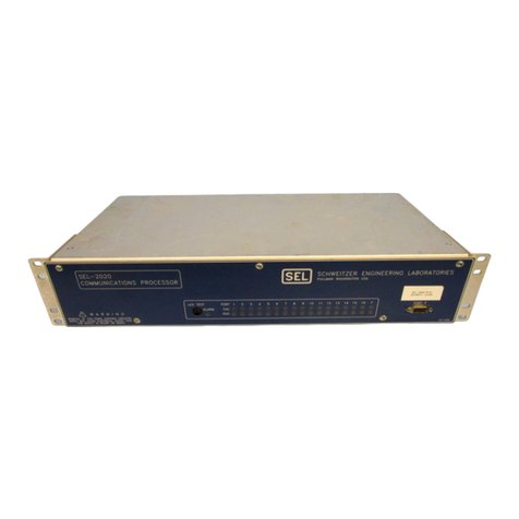
Schweitzer Engineering Laboratories SEL-2711 User manual

SEL-2711
MODBUS PLUS ADAPTER CARD
INSTRUCTION MANUAL
SCHWEITZER ENGINEERING LABORATORIES
2350 NE HOPKINS COURT
PULLMAN, WA USA 99163-5603
TEL: (509) 332-1890 FAX: (509) 332-7990

The software (firmware), schematic drawings, commands, and messages are copyright protected by the United States Copyright Law and
International Treaty provisions. All rights are reserved.You may not copy, alter, disassemble, or reverse-engineer the software. You may not
provide the software to any third party.
All brand or product names appearing in this document are the trademark or registered trademark of their respective holders.
Schweitzer Engineering Laboratories, Inc., , SELOGIC, Connectorized, and Job Done are registered trademarks of Schweitzer Engineering
Laboratories.
The English language manual is the only approved SEL manual.
Copyright © SEL 1997, 1998, 2001 (All rights reserved) Printed in USA.

Date Code 20010105 Manual Change Information i
SEL-2711 Instruction Manual
MANUAL CHANGE INFORMATION
The date code at the bottom of each page of this manual reflects the creation or revision date. Date
codes are changed only on pages that have been revised and any following pages affected by the
revisions (i.e., pagination). If significant revisions are made to a section, the date code on all pages
of the section will be changed to reflect the revision date.
Each time revisions are made, both the main table of contents and the affected individual section
table of contents are regenerated and the date code is changed to reflect the revision date.
Changes in this manual to date are summarized below (most recent revisions listed at top).
Revision
Date Summary of Revisions
The Manual Change Information section has been created to begin a record of revisions to this
manual. All changes will be recorded in this Summary of Revisions table.
20010105 Section 4 - made typographical corrections.
Appendix A - Updated firmware to work with SEL-2030 Communications
Processor interface changes.
981030 Section 4, Target Type - updated information
980601 Section 4 - Added Summary Card
980420 All Sections updated to describe new features in firmware release
SEL-2711-R102
971218 Appendix A - Correction


Date Code 20010105 Table of Contents i
SEL-2711 Instruction Manual
SEL-2711 INSTRUCTION MANUAL
TABLE OF CONTENTS
SECTION 1: INTRODUCTION
SECTION 2: GENERAL DESCRIPTION
SECTION 3: OPERATION AND NETWORK CONFIGURATION
SECTION 4: OPERATION WITHIN SEL-2030
APPENDICES
Appendix A: Firmware Versions in this Manual
Appendix B: Error Codes and Messages
Appendix C: Modbus Plus Message Example


Date Code 980420 Introduction i
SEL-2711 Instruction Manual
TABLE OF CONTENTS
SECTION 1: INTRODUCTION .................................................................. 1-1
References................................................................................................................................1-1
Manual Overview.....................................................................................................................1-1
Background Information....................................................................................................1-1
Section Highlights.............................................................................................................1-2
Conventions..............................................................................................................................1-2
Acronyms, Abbreviations, and Definitions ................................................................................1-2


Date Code 980420 Introduction 1-1
SEL-2711 Instruction Manual
SECTION 1: INTRODUCTION
This section provides an introduction to the manual. This section includes a list of references, an
overview of the manual, a list of conventions used within this manual, and a list of acronyms,
abbreviations, and glossary terms.
We, the employee-owners of Schweitzer Engineering Laboratories, Inc., are devoted to making
electric power safer, more reliable, and more economical. The SEL-2711 Modbus Plus Adapter
Card is designed to assist in meeting this objective.
We appreciate your interest in SEL products and we are dedicated to making sure you are satisfied.
If you have any questions about the SEL-2711 or this manual, please contact us at:
Schweitzer Engineering Laboratories, Inc.
2350 NE Hopkins Court
Pullman, WA USA 99163-5603
Tel: (509)332-1890
Fax: (509)332-7990
We guarantee prompt, courteous, and professional service.
We appreciate any comments or suggestions about new products or product improvements that
would help us make your job easier.
REFERENCES
SEL-2030 Communications Processor User’s Guide
SEL-2020/2030 Communications Processor Reference Manual
Modbus Plus™ Network Planning and Installation Guide
MANUAL OVERVIEW
Background Information
This manual is designed to help you make the most effective use of the SEL-2711 Modbus Plus
Communications Adapter. Each section begins with a detailed table of contents followed by a
short paragraph summarizing the main areas of the section. For more information on the
SEL-2030 or Modbus Plus networks, please see the references listed above.
If you are new to Modbus Plus networks you will want to read sections 2 and 3 to get a good
overview of Modbus Plus and of the SEL-2711. If you are already familiar with Modbus Plus
networks, you can skip directly to section 4 and use section 3 for reference.

1-2 Introduction Date Code 980420
SEL-2711 Instruction Manual
Section Highlights
The following list summarizes the main purpose of each section:
• Section 2: General Description, provides an overview of Modbus Plus networking and a
description of the SEL-2711.
• Section 3: Operation and Network Configuration, describes SEL-2711 operation and
configuration.
• Section 4: Operation Within SEL-2030, provides detailed information on how to use the
SEL-2711 within the SEL-2030 including data maps.
• Appendix A: Firmware Versions, lists the firmware versions this manual applies to.
• Appendix B: Error Codes and Messages, lists the error codes and messages the SEL-2711
generates along with a description of why they might occur.
• Appendix C: Modbus Plus Message Example, illustrates how Modbus Plus application
messages are constructed.
CONVENTIONS
Numbers within this manual are generally shown as decimal values. When a number is shown in
hexadecimal, the letter ‘h’ is appended to the number. For instance, 11 is the decimal number
eleven, but 11h is the hexadecimal number eleven, which is equal to the decimal value 17.
Commands to be entered at a terminal are shown in bold all-caps. Literal terminal screen captures
are shown in a box, like the following example:
*>SET P 17<ENTER>SET P 17<ENTER>
.
.
.
ACRONYMS, ABBREVIATIONS, AND DEFINITIONS
Acronym/
Abbreviation Definition
CPU Central Processing Unit
LED Light Emitting Diode
LSB Least Significant Byte
Modbus Plus™ A 1 Megabit/sec, token-passing network proprietary to Schneider
Automation
MSB Most Significant Byte
node A device connected to the network
RAM Random Access Memory
SEL Schweitzer Engineering Laboratories

Date Code 980420 General Description i
SEL-2711 Instruction Manual
TABLE OF CONTENTS
SECTION 2: GENERAL DESCRIPTION................................................... 2-1
Network Overview....................................................................................................................2-1
Basic Network Topologies.................................................................................................2-1
Modbus Plus Message Routing..........................................................................................2-2
Modbus Plus Routing Paths.......................................................................................2-2
Paths to Programmable Controllers............................................................................2-2
Paths to Network Adapters........................................................................................2-3
Paths to Bridge Multiplexers......................................................................................2-3
Modbus Plus Transactions ................................................................................................2-3
Path Types ................................................................................................................2-3
Path Quantities..........................................................................................................2-4
Queuing ....................................................................................................................2-4
Modbus Data Access Commands ......................................................................................2-4
Modbus Data Addressing..................................................................................................2-5
Product Overview.....................................................................................................................2-5
TABLES
Table 2.1: Modbus Data Access Commands ......................................................................................2-5
FIGURES
Figure 2.1: Application Overview.......................................................................................................2-1
Figure 2.2: Message Frame Routing Path............................................................................................2-2
Figure 2.3: SEL-2711 Block Diagram.................................................................................................2-6


Date Code 980420 General Description 2-1
SEL-2711 Instruction Manual
SECTION 2: GENERAL DESCRIPTION
This section provides overviews of Modbus Plus networks and of the SEL-2711 Modbus Plus
Adapter functionality.
NETWORK OVERVIEW
This subsection provides an overview of Modbus Plus. See Modbus Plus Network Planning and
Installation Guide for a more complete description of Modbus Plus networks.
Basic Network Topologies
Each device on a Modbus Plus network is a peer node, handling the token in its assigned address
sequence. Potentially, any node can exchange data with any other node. Figure 2.1 shows a
typical network configuration. More complex schemes are possible using bridges and repeaters.
See Modbus Plus Network Planning and Installation Guide for more information about Modbus
Plus networks and connection possibilities.
Figure 2.1: Application Overview

2-2 General Description Date Code 980420
SEL-2711 Instruction Manual
Modbus Plus Message Routing
Each device establishes itself as a node on the Modbus Plus network. Up to 64 nodes can be
present on a single network, each with a unique address from 1 to 64. Multiple networks can be
joined through Bridge Plus devices.
Modbus Plus Routing Paths
Nodes address each other using a routing path field of five bytes. The path is embedded in the
Modbus Plus message frame as sent from the originating node. The five bytes of routing allow
destination nodes to be addressed up to four networks away from the originating node. The routing
bytes are used by each type of device in a specific way, as illustrated in Figure 2.2.
Figure 2.2: Message Frame Routing Path
The example in Figure 2.2 shows routing to a controller through three networks that are joined by a
pair of Bridge Plus devices. Using the routing bytes in the example, the message will be sent first
to node 25, a Bridge Plus on the local network. That bridge forwards the message to a second
Bridge Plus at node address 20 on the second network. The second bridge forwards the message to
its final destination, a controller at node address 12 on the third network. The zero contents of
bytes 4 and 5 specify that no further routing will occur.
The routing path contents are specific to the type of device at the destination. Routing path
methods for various networked devices are outlined below. For further details about message
routing paths, see your Modbus Plus Network Planning and Installation Guide
(GM-MBPL-001).
Paths to Programmable Controllers
For 984 programmable controllers, including the AT-984 and M-984, the last non-zero byte in the
routing specifies the network node address of the controller (range: 1 ... 64). For example, the path
5.0.0.0.0 specifies a controller node at address 5 on the local network (the network to which the
host is attached).

Date Code 980420 General Description 2-3
SEL-2711 Instruction Manual
Paths to Network Adapters
For host-based network adapters such as the SA85, and SM85, the next-to-last non-zero byte
specifies the adapter's network node address (range: 1 … 64). The last non-zero byte specifies an
application task number (range: 1 … 8) to which the message is to be assigned. For example, if an
adapter is at node address 35 on the local network, the path 35.8.0.0.0 specifies routing to task 8 in
that adapter.
Paths to Bridge Multiplexers
For BM85 bridge multiplexers, the routing field contents are specific to the slave device configu-
ration at the multiplexer's Modbus port. Either a single slave device or a network of slave devices
can be connected at the port.
A single slave device at a multiplexer's Modbus port is addressed using two bytes. The next-to-last
non-zero byte addresses the multiplexer node (range: 1 … 64). The last non-zero byte specifies the
port (range: 1 … 4) to which the slave device is attached. Specifying the port automatically
addresses the device at that port. For example, if a BM85 is at node address 25 on the local
network, 25.1.0.0.0 routes a message to the single slave device at the multiplexer's port 1.
A networked slave device at the multiplexer's port is addressed using three bytes. The third-from-
last non-zero byte addresses the multiplexer node (range: 1 ... 64). The next-to-last non-zero byte
specifies the port (range: 1 ... 4) to which the network is attached. The last non-zero byte specifies
the Modbus address of the slave device (range: 1 ... 247). For example, 25.2.200.0.0 routes a
message to multiplexer node address 25, port 2, slave device 200.
Modbus Plus Transactions
With multiple node devices processing messages asynchronously on the network, an individual
device might have several concurrent transactions in process. Each device has multiple internal
paths of various types to allow concurrent processing of transactions. It opens a path when a
transaction begins, keeps it open during processing of the transaction, and closes it when the
transaction terminates. When the path is closed, it becomes available to another transaction.
Both the originating and destination devices open paths for a mutual transaction and maintain the
paths until the transaction completes. If the transaction passes through Bridge Plus devices to a
destination on another network, each bridge opens and maintains a path at each of its two network
ports. Thus, a logical path is established between the originating and destination devices and
maintained until the transaction is finished. When the transaction is completed, all of the paths it
has used will be freed.
Path Types
Each Modbus Plus device contains the following types of paths:
Data Master (DM) Path This type of path is opened for data reads and writes, and for get and
clear remote statistics, as they are originated in the device.
Data Slave (DS) Path This type of path is opened for data reads and writes as they are received
by the device.

2-4 General Description Date Code 980420
SEL-2711 Instruction Manual
Program Master (PM) Path This type of path is opened for programming commands as they are
originated in the device.
Program Slave (PS) Path This type of path is opened for programming commands as they are
received by the device.
Each path is independent of the others. Activity in one path does not affect the performance of the
other paths.
Path Quantities
The following path quantities are available in the Modbus Plus devices:
Path Host Based 984s BM85 BP85 SA85/SM85/SQ85 SEL-2711
Data Master 8* 4 8 8 8
Data Slave 4 4 8 8 8
Program Master 8* 4 8 8 0
Program Slave 1 4 8 8 0
*Because the host-based controllers have a virtual network adapter capability built in, their path
quantities are different from other types of 984 controllers.
Queuing
If all DS paths are active in a device, new incoming transactions will be queued. Transactions will
remain queued until a path is available, and will then be removed from the queue and given the
path. A final data response will not be returned to the originating application until a full path is
available from origin to destination.
When the destination node removes a transaction from its queue, it will wait for the network token
and then will request the command again from the originating node. The originator will retransmit
the command while the destination retains the token. This process occurs transparently,
eliminating the need for polling between the origin and destination devices in the application.
BP85 Bridge Plus Queuing Messages which must pass through multiple bridges will be queued
(if necessary) within the first bridge, but will not be queued within any subsequent bridges. An
attempt to queue in a second bridge will return an error code, which can be tested by the
application program in the originating node. This prevents unpredictable delays from queuing
across several networks. The originating application can determine how to proceed with
outstanding tasks, rather than having to wait through multiple levels of queuing. Tasks that are
currently in progress can be allowed to continue or can be aborted in favor of a higher priority
task.
Modbus Data Access Commands
Transactions to or from programmable controller nodes are based on Modbus data access com-
mands that are embedded into Modbus Plus frames. These commands are recognized by con-
trollers for reading and writing coils and registers and for reporting status. The following Modbus
commands are used:

Date Code 980420 General Description 2-5
SEL-2711 Instruction Manual
Table 2.1: Modbus Data Access Commands
Function Code (Decimal) Command Name
1** Read Discrete Output Status (0xxxx)
2Read Discrete Input Status (1xxxx)
3** Read Output Register (4xxxx)
4** Read Input Register (3xxxx)
5** Force Single Coil (0xxxx)
6Preset Single Register (4xxxx)
7Read Exception Status
8* Get/Clear Network Statistics (Subfunction 21)
15 Force Multiple Coils (0xxxx)
16 Preset Multiple Registers (4xxxx)
17 Report Slave ID
*Use only subfunction 21 of function 8 for Modbus Plus networking data.
** These function codes are supported by the SEL-2711
Modbus Data Addressing
Modbus Plus addresses typically have the following ranges:
Coils (Output Status) 1-9999
Input Status 10001 -19999
Input Registers 30001 -39999
Holding (Output) Registers 40001 -49999
These address ranges imply what function codes can be used on the data. For instance, holding
registers can be accessed using function codes 3, 6, and 16 (see Table 2.1).
The actual addresses passed in the Modbus Plus messages start at 0. For example, for holding
registers, the address within the message is 40001 less than what is viewed by the user.
See Appendix C: Modbus Plus Message Example to see how an actual Modbus Plus message is
structured.
PRODUCT OVERVIEW
The SEL-2711 allows a remote Modbus Plus device to read meter, demand meter, target, and
history information available from the host system. It also allows User Region data to be read.
The SEL-2711 can be configured to send user-configurable Modbus Plus global data. The
SEL-2711 captures all Modbus Plus global data from the network and stores it to a data region so
it is available to the host system. The SEL-2711 accepts control operations; the host system

2-6 General Description Date Code 980420
SEL-2711 Instruction Manual
defines their specific function. The SEL-2711 can also issue control commands to other nodes
based on control indications from the host system.
In Section 3: Operation and Network Configuration, there is a complete description of data
access methods and SEL-2711 operation. In Section 4: Operation Within SEL-2030, there is a
description of the register addresses applicable to this data.
Figure 2.3: SEL-2711 Block Diagram
Figure 2.3 shows a block diagram of the SEL-2711. To communicate with the host system, the
SEL-2711 talks to a block of shared memory that is resident on the host system. The SEL-2711
can then operate on the data using its local CPU and memory. The Modbus Plus Peer Processor
controls the Modbus Plus network operations. It interacts with the local CPU using a small dual-
port RAM.

Date Code 980420 Operation and Network Configuration i
SEL-2711 Instruction Manual
TABLE OF CONTENTS
SECTION 3: OPERATION AND NETWORK CONFIGURATION............. 3-1
Introduction..............................................................................................................................3-1
Data Access .............................................................................................................................3-1
LED Usage...............................................................................................................................3-2
Self-Tests.................................................................................................................................3-3
Device Configuration................................................................................................................3-3
Network Configuration.............................................................................................................3-4
TABLES
Table 3.1: SEL-2711 Settings............................................................................................................3-3
FIGURES
Figure 3.1: SEL-2711 Panel with Label ..............................................................................................3-4

Table of contents
Other Schweitzer Engineering Laboratories Computer Hardware manuals