Schweizer Solrif User manual

Solar systems by Schweizer:
Mounting Instructions – Solrif®
Ernst Schweizer AG
Bahnhofplatz 11
8908 Hedingen, Switzerland
Telephone +41 44 763 61 11
solar@ernstschweizer.ch
www.ernstschweizer.ch
Mounting Instructions – Solrif ®
Technical data subject to change
November 2022
© Ernst Schweizer AG
Page 1/15

Solar systems by Schweizer:
Mounting Instructions – Solrif
®
Ernst Schweizer AG
Bahnhofplatz 11
8908 Hedingen, Switzerland
Telephone +41 44 763 61 11
solar@ernstschweizer.ch
www.ernstschweizer.ch
Mounting Instructions – Solrif ®
Technical data subject to change
November 2022
© Ernst Schweizer AG
Page 2/15
Contents
Scope of application ��������������������������������������������������������������������������� 3
Exclusion of liability ���������������������������������������������������������������������������� 3
Explanation of symbols ���������������������������������������������������������������������� 4
Requirements for the roof ����������������������������������������������������������������� 4
Hazards due to electrical energy������������������������������������������������������� 5
Transport and packaging������������������������������������������������������������������� 5
Supplementary information���������������������������������������������������������������� 5
Mounting inside corners �������������������������������������������������������������������� 5
Preparation ��������������������������������������������������������������������������������������� 6
Working area ������������������������������������������������������������������������������������ 6
Solrif
®N to Solrif
®D�������������������������������������������������������������������������� 6
Earthing ��������������������������������������������������������������������������������������������� 6
Overview ������������������������������������������������������������������������������������������� 7
Materials and tools ��������������������������������������������������������������������������� 7
Safety ����������������������������������������������������������������������������������������������� 7
Horizontal and vertical section ���������������������������������������������������������� 8
Mounting the Solrif
® eld ������������������������������������������������������������������ 9
Maintenance and cleaning ���������������������������������������������������������������� 15
Replacing modules ��������������������������������������������������������������������������� 15
Disinstallation and disposal �������������������������������������������������������������� 15

Solar systems by Schweizer:
Mounting Instructions – Solrif
®
Ernst Schweizer AG
Bahnhofplatz 11
8908 Hedingen, Switzerland
Telephone +41 44 763 61 11
solar@ernstschweizer.ch
www.ernstschweizer.ch
Mounting Instructions – Solrif ®
Technical data subject to change
November 2022
© Ernst Schweizer AG
Page 3/15
Scope of application
– This system has been designed solely for the generation of electricity from solar energy
and as weather protection�
– The mounting of full-surface PV installations, where the PV eld extends to the roof edges,
is possible, but is not covered by these mounting instructions�
– Solrif
®modules are solely designed for in-roof mounting in accordance with this manual�
– Information on electrical connections, earthing and wiring can be found in the relevant plans
and component instructions�
– Correct use includes observing all the information in this manual�
– These instructions apply to the Solrif
®N as well as to the Solrif
®D system�
– The sheet metal surround is designed and tested for typical interlocking tiles� Its suitability for other
roof coverings or connection to roof edges and roof superstructures must be assessed by a specialist;
if necessary, transition sheets must be made by a roong materials specialist. Suggested solutions
can be found at www�solrif�com�
Any use of the system that goes beyond correct use, as well as any different use of the system or of the
Solrif
®modules, counts as incorrect use and can lead to dangerous situations�
Illustrations in this manual are intended for basic understanding, and may deviate from the actual design
of the system�
Exclusion of liability
– The information and safety instructions in this manual have been compiled taking into account the
currently applicable norms, guidelines and regulations, the latest technology and the accumulated
experience of Ernst Schweizer AG�
– The shipment contents, or the design of the system, can deviate from the descriptions and diagrams
specied in this manual because of optional items ordered, manufacture of customised designs or
the latest technological changes�
– Apart from the contractually agreed obligations, the manufacturer's General Terms and Delivery Conditions
apply� These are subject to the laws that were valid at the juncture when the contract was concluded�
– Ernst Schweizer AG reserves the right to make technical changes to the system as part of further
development to improve performance characteristics and safety�
– Ernst Schweizer AG accepts no liability for damages and accidents arising from the following causes:
– Inappropriate use of the mounting system
– Non-observance of the information and instructions in this manual
– Work carried out on or with the system by non-qualied or unauthorised personnel
– Yield losses due to electrical defects of the modules

Solar systems by Schweizer:
Mounting Instructions – Solrif
®
Ernst Schweizer AG
Bahnhofplatz 11
8908 Hedingen, Switzerland
Telephone +41 44 763 61 11
solar@ernstschweizer.ch
www.ernstschweizer.ch
Mounting Instructions – Solrif ®
Technical data subject to change
November 2022
© Ernst Schweizer AG
Page 4/15
Explanation of symbols
Warning of electric shock
Note
proMSP
Follow SPT software report
Use a harness Wear safety goggles
Wear working gloves Wear safety shoes
Wear a helmet Wear ear protection
Sawing/cutting work step Make electrical connection
Requirements for the roof
– Roof pitch: 10° to 75° (with foil underroof)
– Underlay, sub-roof membrane against condensate and moisture according to ZVDH/SIA 232/1,
temperature resistance up to 80° C
– Wooden substructure: analogous to tiled roof or on vertical counter battens�
– Wood quality: Strength category C24
Allow an additional requirement of 10% for wood offcuts compared to the batten plan� In addition,
keep a range of auxiliary material to hand to smooth out any irregularities in the roof construction or
to be able to implement connections or linings�
Note
Permissible deviation from the atness of the substructure 0,5 % (5 mm per metre)
Note
Stepping on modules that have already been laid can lead to cell breakage and, in the long term,
to a reduction in performance� If unavoidable, please follow the manufacturer’s instructions or only
use the appropriate devices�
proMSP

Solar systems by Schweizer:
Mounting Instructions – Solrif
®
Ernst Schweizer AG
Bahnhofplatz 11
8908 Hedingen, Switzerland
Telephone +41 44 763 61 11
solar@ernstschweizer.ch
www.ernstschweizer.ch
Mounting Instructions – Solrif ®
Technical data subject to change
November 2022
© Ernst Schweizer AG
Page 5/15
Hazards due to electrical energy
WARNING
– Solar modules produce electricity when light falls on them�
– Have work on the electrical system carried out only by qualied electricians.
– Observe the regulations applicable at the installation site�
– If modules are found to be damaged, please contact the supplier�
– In case of damage to the cable insulation, immediately disconnect the power circuit
and arrange for repair�
– Do not connect or disconnect cable assemblies if they are carrying current�
– Make sure that the maximum permissible system voltage is not exceeded when connecting
the modules in series�
Note
– Make sure that when modules are connected in parallel, each row is individually protected
by a fuse�
– Observe the instructions of the module manufacturer and of the system planner�
– Observe the information sheet on equipotential bonding and lightning protection at
www�solrif�com�
Transport and packaging
Please observe the handling instructions on the packaging� If the goods or the packaging show any defects,
please contact the supplier�
– Do not set the module down on its glass rim� Risk of damage to property!
– Leave the module in its original packaging until immediately prior to insertion into the PV array�
– Never hold or carry the module under any circumstances by its connection cables or junction box�
Supplementary information
You will nd further information at www.solrif.com in the following documents:
– Application range of Solrif with regard to watertightness and minimum requirements for the roof underlay
– Lightning protection concept
– Information sheet for lightning and overvoltage protection with Solrif
®
– Fire protection requirements with Solrif
®in Switzerland
– Application range for Solrif
®with elevated snow loads
– Leaet on the use of Solrif
®on curved roofs
– Blind Modules leaet for Solrif
®in-roof PV system
Mounting inside corners
The mounting of the sheet metal surround for PV elds with inner corners is
described in the supplementary document ‘Short mounting instructions – Solrif
®,
supplementary information for the installation of inner corners’�
Ernst Schweizer AG
Bahnhofplatz 11
8908 Hedingen, Switzerland
Telephone +4144 763 61 11
ernstschweizer.ch
Short installation manual – Solrif® Inner corners
Technicaldata subject to change
November 2021
© Ernst Schweizer AG
Page 1/10
Solar systems by Schweizer:
Short installation manual – Solrif®
Additional information for the mounting of inner corners
Scope of application
These Short installation manual form part of the currently valid
‘Installation manual PV Roof Integration Solrif®’ of 6.5.2019.
They describe a partial roof solution and can also be applied
by analogy for whole-roof solutions.

Solar systems by Schweizer:
Mounting Instructions – Solrif
®
Ernst Schweizer AG
Bahnhofplatz 11
8908 Hedingen, Switzerland
Telephone +41 44 763 61 11
solar@ernstschweizer.ch
www.ernstschweizer.ch
Mounting Instructions – Solrif ®
Technical data subject to change
November 2022
© Ernst Schweizer AG
Page 6/15
Preparation
Before installation, the following documents must be checked for completeness and taken into account:
– Solar�Pro�Tool documentation (SPT), incl� parts list and CAD plan
– Electrical planning (cable routing plan)
– Protection concepts (lightning protection, earthing, equipotential bonding)
– Roof Plan
Working area
– Safety equipment such as scaffolding etc� must be professionally installed before installation�
– Observe the local and national regulations for the installation of PV systems, safety equipment and
electrical systems�
– Check goods and auxiliary equipment for completeness and damage�
Solrif
®N to Solrif
®D
The mounting of the two systems is identical. The systems differ in the module frame and edge prole
geometry, which means that different mounting brackets are required� The same grid dimensions are
assumed for both systems�
Solrif
® N proles Solrif
® D proles
Earthing
If the modules are earthed, then attach the earthing terminal* (article number 21899) as follows:
Preparation: Screw on earthing terminal To connect: Remove 30 mm insulation of the
earthing cable and press into earthing terminal
ANSICHT76 (1 : 2)
30
ANSICHT74 (1 : 5)
K ( 1 : 1 ) M ( 1 : 1 )
17.1
20
K ( 1 : 1 ) M ( 1 : 1 )
17.1
20
*Alternative: Earthing cable set 10mm2 (15092)

Solar systems by Schweizer:
Mounting Instructions – Solrif
®
12
3
4
5
8
12
10
16
7
6
14
13
15
911
①Solrif
®batten
②Wedge plank
③Supporting batten
④Connecting sheet
Materials needed for assembly
– Suitable wood screws for fastening the battens
– ①Solrif
®battens 120 × 30 mm
– ②Wedge plank
– ③Supporting batten
– SPT project report
Tools required
– Cordless screwdriver with Torx T20 bit insert
– Hammer
– Measuring equipment
(e�g� tape measure and chalk line)
– Mounting gauge (recommended)
– Guide line
– Metal saw
Overview
⑤ Eaves prole
⑥ Mounting clamp prole
⑦Mounting clamp glass
⑧Solrif
®PV module
⑨ Flashing prole right
⑩ Flashing prole left
⑪ Side ashing right
⑫ Side ashing left
⑬ Top ashing
⑭ Top ashing joiner
⑮ Corner ashing right
⑯ Corner ashing left
Ernst Schweizer AG
Bahnhofplatz 11
8908 Hedingen, Switzerland
Telephone +41 44 763 61 11
solar@ernstschweizer.ch
www.ernstschweizer.ch
Mounting Instructions – Solrif ®
Technical data subject to change
November 2022
© Ernst Schweizer AG
Page 7/15
Safety

24 RhorRhorRhor
BGR + 240
18
BGR
BGR + 100
BOL BOR
120120
H
K
10
120
20
60
S
ver
30
*
60*
Valley sealing strip (06736)
(if working without an eaves prole).
S
ver
H
K
120
R
ver
R
ver
R
ver
10020
31050
30*
H
G
240
H
G
+240
Solar systems by Schweizer:
Mounting Instructions – Solrif
®
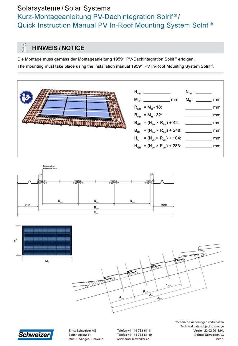
Horizontal section Reference line vertical
Illustration: horizontal section Solrif®
These measurements may be found in the SPT report:
BGR: PV eld width = (Rhor × no� of modules horizontal) +42 mm
BOL: peripheral distance left
BOR: peripheral distance right
HG: PV eld height = (Rver × no� of modules vertical) +100 mm
Rhor horizontal grid measurement = module width -18 mm
Rver vertical grid measurement = module height - 32 mm
Sver: distance 1st Solrif
® batten
proMSP
SPT
Illustration: vertical section Solrif®
* The height of the Solrif
®battens must
be adapted to the tile battens.
Vertical section
Reference line horizontal:
Front edge batten
Roof slope HKWidth
connecting sheet
≥ 30° 50 mm 300 mm
≥ 22° 80 mm 300 mm
≥ 15° 120 mm 2 × 300 mm
≥ 12° 160 mm 2 × 300 mm
≥ 10° 240 mm 3 × 300 mm
Ernst Schweizer AG
Bahnhofplatz 11
8908 Hedingen, Switzerland
Telephone +41 44 763 61 11
solar@ernstschweizer.ch
www.ernstschweizer.ch
Mounting Instructions – Solrif ®
Technical data subject to change
November 2022
© Ernst Schweizer AG
Page 8/15

ANSICHT55 (1 : 10)
ANSICHT52 (1 : 20)
ANSICHT84 (1 : 10)
m
a
x
.
20
0
m
m
Solar systems by Schweizer:
Mounting Instructions – Solrif
®
Remove tiles and, if necessary, also the tile
battens in the area of the module surface on a
generous scale�
Assemble Solrif
®battens, wedge plank and
supporting batten in accordance with instructions�
Fix Solrif
®battens with suitable wood screws in
the vertical grid Rver�
Additional supporting battens 30 × 50 mm
for high snow loads if required�
Attention: Avoid collision with module junction box
Place wedge plank� Lay and install the eaves skirting� If the eaves
skirting is composed of several sections of
ashing tape, the sections must overlap by at
least 100 mm�
ANSICHT82 (1 : 100)
1
3
5
2
4
6
ANSICHT54 (1 : 100)
Mounting the Solrif
® eld
proMSP
SPT
proMSP
SPT
proMSP
SPT
proMSP
SPT
Ernst Schweizer AG
Bahnhofplatz 11
8908 Hedingen, Switzerland
Telephone +41 44 763 61 11
solar@ernstschweizer.ch
www.ernstschweizer.ch
Mounting Instructions – Solrif ®
Technical data subject to change
November 2022
© Ernst Schweizer AG
Page 9/15

Solar systems by Schweizer:
Mounting Instructions – Solrif
®
Position the eaves prole and prole xing.
ANSICHT90(1:20)
Szene 2, Ansicht88
8
ANSICHT91 (1 :2)
Szene 2, Ansicht89
Align eaves prole with reference (blue) and
prole xing to BOR. Insert eaves prole up to the
stopping point of the prole xing.
ANSICHT100 (1 :2)
Szene 2, Ansicht90
BORBGR
9
proMSP
SPT
ANSICHT96 (1 :2)
Szene 2, Ansicht96
B
GR
B
OR
ANSICHT93(1:20)
Szene 2, Ansicht92
Slide the next eaves prole under the prole xing
to the stopping point and align with the reference�
Repeat until the end of the PV eld.
11
ANSICHT102 (1 :2)
Szene 2, Ansicht94
ANSICHT92 (1 :20)
Szene 2, Ansicht91
Turn and screw the prole xing.
Observe position marks: approx� 3 mm clearance
to the end of the eaves prole.
10
ANSICHT101 (1 :2)
Szene2,Ansicht 91
ANSICHT94(1:2)
Szene 2, Ansicht93
Overview of eaves prole installation.
ANSICHT122 (1:10)
Szene 2, Ansicht 100
7
Ernst Schweizer AG
Bahnhofplatz 11
8908 Hedingen, Switzerland
Telephone +41 44 763 61 11
solar@ernstschweizer.ch
www.ernstschweizer.ch
Mounting Instructions – Solrif ®
Technical data subject to change
November 2022
© Ernst Schweizer AG
Page 10/15
Shorten last eaves prole compared to BGR
by a minimum of 11 mm�
ANSICHT103 (1 :2)
Szene2,Ansicht 98
11
BOL BGR
12
proMSP
SPT

Solar systems by Schweizer:
Mounting Instructions – Solrif
®
ANSICHT42 (1 : 20)
Screw on further prole mounting brackets
and glass mounting brackets (number as per
SPT report)�
15
proMSP
SPT
Attach further mounting brackets for the following
modules�
ANSICHT44 (1 : 30)
16
proMSP
SPT
ANSICHT56 (1 : 20)
Insert right side ashing with ashing prole into
bracket�
17
ANSICHT64 (1 : 2)
ANSICHT57 (1 : 30)
First place the module with the left frame prole in
the mounting bracket, then lay it down�
18
ANSICHT65 (1 : 2)
ANSICHT66 (1 : 2)
ANSICHT50 (1 : 10)
18
Fasten the mounting gauge to the eaves prole,
place the mounting clamp prole with the help
of the mounting gauge�
14
proMSP
SPT
ANSICHT40(1:2)
Szene2,Ansicht 25
ANSICHT41(1:3)
Szene 2, Ansicht26
ANSICHT104 (1 :2)
Szene 2, Ansicht34
Ernst Schweizer AG
Bahnhofplatz 11
8908 Hedingen, Switzerland
Telephone +41 44 763 61 11
solar@ernstschweizer.ch
www.ernstschweizer.ch
Mounting Instructions – Solrif ®
Technical data subject to change
November 2022
© Ernst Schweizer AG
Page 11/15
Place and screw the last prole xing.
Have regard to the position marks�
ANSICHT95(1:5)
Szene2,Ansicht 95
13
ANSICHT99(1:2)
Szene 2, Ansicht99
B
OL
B
GR

Solar systems by Schweizer:
Mounting Instructions – Solrif
®
ANSICHT59 (1 : 20)
Close off at the left edge with side ashing and
ashing prole.
20
ANSICHT68 (1 : 2)
ANSICHT51 (1 : 20)
Mount the next row of mounting clamps�
If you are working without a mounting gauge,
leave 15 mm distance between mounting clamp
and module�
21
proMSP
SPT
ANSICHT63 (1 : 30)
Close off on the left with side ashing and ashing
prole.
24
Insert the connection plate and edge prole in the
prole bracket as far as they will go.
ANSICHT61 (1 : 30)
22
ANSICHT60 (1 : 5)
ANSICHT62 (1 : 30)
Lay further modules and connect electrically�
23
ANSICHT60 (1 : 5)
ANSICHT58 (1 : 50)
Lay further modules and connect electrically�
19
ANSICHT67 (1 : 2)
Ernst Schweizer AG
Bahnhofplatz 11
8908 Hedingen, Switzerland
Telephone +41 44 763 61 11
solar@ernstschweizer.ch
www.ernstschweizer.ch
Mounting Instructions – Solrif ®
Technical data subject to change
November 2022
© Ernst Schweizer AG
Page 12/15

ANSICHT87 (1 : 10)
ANSICHT69 (1 : 30)
3
1
0
Solar systems by Schweizer:
Mounting Instructions – Solrif
®
Insert top ashing.
Insert the corner plate on the right and x it with
a wide-headed pin�
26
27
Push in the bumper plates and x them with a
wide-headed pin�
ANSICHT70 (1 : 10)
28
ANSICHT45 (1 : 20)
Lay top prole bracket row (‘top row’ position).
25
proMSP
SPT
ANSICHT47 (1 : 10)
Ernst Schweizer AG
Bahnhofplatz 11
8908 Hedingen, Switzerland
Telephone +41 44 763 61 11
solar@ernstschweizer.ch
www.ernstschweizer.ch
Mounting Instructions – Solrif ®
Technical data subject to change
November 2022
© Ernst Schweizer AG
Page 13/15

ANSICHT72 (1 : 2)
ANSICHT48 (1 : 85)
Solar systems by Schweizer:
Mounting Instructions – Solrif
®
Attach sheet metal clamps and x them
with a wide-headed pin�
Flashing xing positions:
2 per side ashing;
3 per top ashing;
1 per corner ashing.
Replace tiles on roof, where necessary adjust
and x the tiles in a professional manner.
30
32
31
ANSICHT71 (1 : 10)
Push in the corner plate on the left and x it
with a wide-headed pin�
29
Ernst Schweizer AG
Bahnhofplatz 11
8908 Hedingen, Switzerland
Telephone +41 44 763 61 11
solar@ernstschweizer.ch
www.ernstschweizer.ch
Mounting Instructions – Solrif ®
Technical data subject to change
November 2022
© Ernst Schweizer AG
Page 14/15

Solar systems by Schweizer:
Mounting Instructions – Solrif
®
Ernst Schweizer AG
Bahnhofplatz 11
8908 Hedingen, Switzerland
Telephone +41 44 763 61 11
solar@ernstschweizer.ch
www.ernstschweizer.ch
Mounting Instructions – Solrif ®
Technical data subject to change
November 2022
© Ernst Schweizer AG
Page 15/15
Maintenance and cleaning
Unless otherwise specied by the module manufacturer, it is recommended to check the PV array for
damage annually and after severe weather events such as storms or hailstorms� In case of heavy soiling, it is
recommended to clean the modules and module drainage channels� If the yield changes, the electrical
installation must be checked by a specialist�
Replacing modules
1� Move the module to the left of the defective module upwards, e�g� with the aid of glass suction cups,
until it comes free from the mounting brackets at the lower edge (when replacing modules at the left edge
of the generator eld, the edge prole must be pushed upwards).
2� Lift up the right-hand corner of the module to the left of the defective module by about 3 to 5 cm and
secure the module in this position using a wooden wedge�
3� Shift the defective module upwards until it detaches from the mounting clamps on the bottom edge�
4� Lift up the defective module by the bottom edge and pull it downward and out�
5� Disconnect the connections to the neighbouring modules in the cable group and secure the loose cable
ends of the neighbouring modules so that these do not ‘disappear’ between the PV array and the roof
underlay�
6� Disconnect the equipotential bonding cable�
7� Remove the defective module�
8. Thread the replacement module under the lifted module or edge prole to the left of it until the equipoten-
tial bonding cable can be placed in the earthing terminal, and clamp it in place again�
9� Establish connections to the neighbouring modules in the cable group�
10� Now push the replacement module further under the module above it (at the upper edge of the generator
eld: under the connection plate) until the stop point is reached and lay it down.
11� Pull the replacement module downwards until it clicks into place into the bottom mounting clamps�
12� Remove the wooden wedge under the right-hand bottom corner of the module to the left of the replace-
ment module�
13. Pull the module or the edge prole to left of the replacement module downwards until it clicks into place
in the lowermounting clamps�
Disinstallation and disposal
Disinstallation and disposal of PV systems may only be carried out by qualied specialist rms. Have
dismantling and disposal carried out only by a specialist company for roof-integrated photovoltaic systems�
Other manuals for Solrif
4
Table of contents
Other Schweizer Solar Panel manuals
Popular Solar Panel manuals by other brands

Tsun
Tsun TSOL-ESK350 Quick installation guide

LUTEC
LUTEC ARROW 6910601335 user manual

NEO TOOLS
NEO TOOLS 90-140 Original manual

AEG
AEG AS-M 7-S Series installation manual

Plug-In Solar
Plug-In Solar Sheet Metal/Flat Roof Mount Kit installation instructions

Third Wave Power
Third Wave Power mPOWERPAD XPAND user guide