Scientific Aviation SOOFIE User manual

Installation
Guide
Version 1.0
July 2020

SOOFIE parts list
Label Qty. Description
A x1 SOOFIE enclosure with Unistrut channel
B x1 solar panel
C x1 solar panel upper bracket
D x2 solar panel lower brackets
E x4 Unistrut clamps
F x2 1.5-foot-long Unistrut channel
G x4 square Unistrut washers
Bag: x4 10-32 x 2”pan head Phillips machine screws
x4 ¼”-20 x⅝” hex head bolts
x4 ¼”-20 x 1-¾” hex head bolts
x8 ¼” screw size split ring lock washers
x8 ¼”-20 hex nuts
x2 splashproof fuse receptacle caps
x2 10 Amp medium-blow cartridge fuses
ABC
E
F
G
Bag
D

Anemometer parts list
Label Qty. Description
Sx1 sonic anemometer
Tx1 cable
Ux1 mounting stub
Vx3 10-32 x 3/8” pan head
Phillips machine screws
Wx2 hose clamps
S
U
T
V
W

Needed for installation:
Phillips screwdriver, 2-point tip
Slotted screwdriver, 1/4” tip
3/8” drive ratchet handle
5/16”, 7/16” and 1/2” sockets
9/16” deep socket
7/16” and 1/2” open-ended wrenches
6” diagonal cutting pliers
8” slip-joint pliers
Tape measure
Marker pen
MC4 solar connector tool
Optional:
Electric screwdriver set with Phillips
tip, slotted tip, and hex sockets as
listed above
Adjustable wrench
Multimeter
Installation tools (supplied by the user)
Tools

Installation procedure

1a. (if applicable) Attach the anemometer to the stub.
1) Attach the cable to the anemometer;
ensure bayonet connector is locked.
2) Pass the cable through the mounting stub
and attach the stub to the anemometer
using three 10-32 x 3/8” pan head Phillips
machine screws.

1b. (if applicable) Attach the anemometer to the pole.
4) Position the anemometer & stub assembly
at the top of the pole on the South side.
Install two hose clamps around the stub
and the pole and spaced 3” apart.
5) Orient the assembly so the measurement
plane is horizontal and the North arrows
and colored security seal (circled below)
point to true North after the hose clamps
are securely tightened.

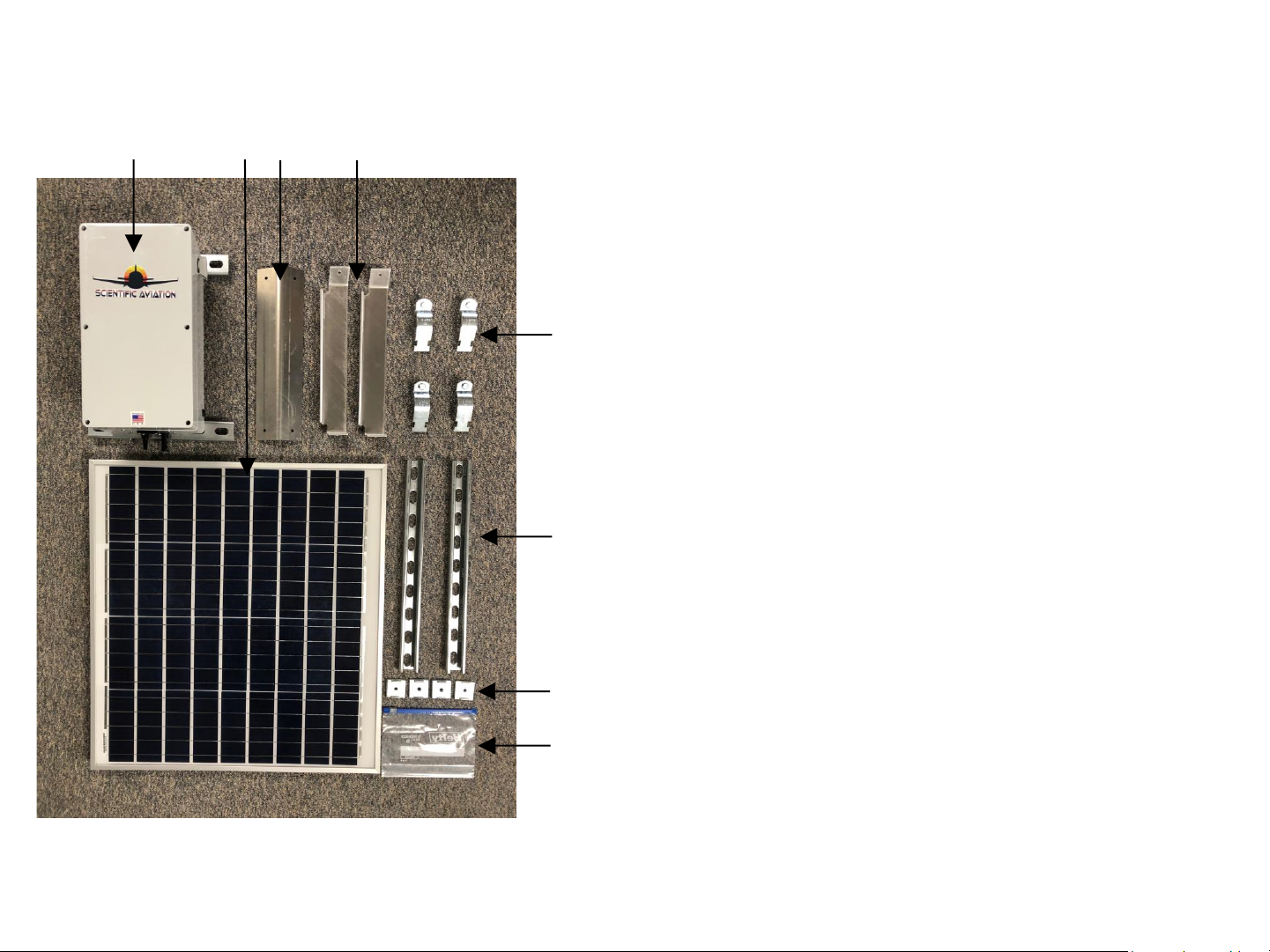
2a. Attach the solar panel to its mounting frame.
1) Measure & mark the pole at 6”, 14”, and 31” from the top.
2) Position the solar panel upper mounting bracket with the bend
facing the solar panel and attach with two ¼-20 x 5/8” hex head
bolts, lock washers, and nuts.
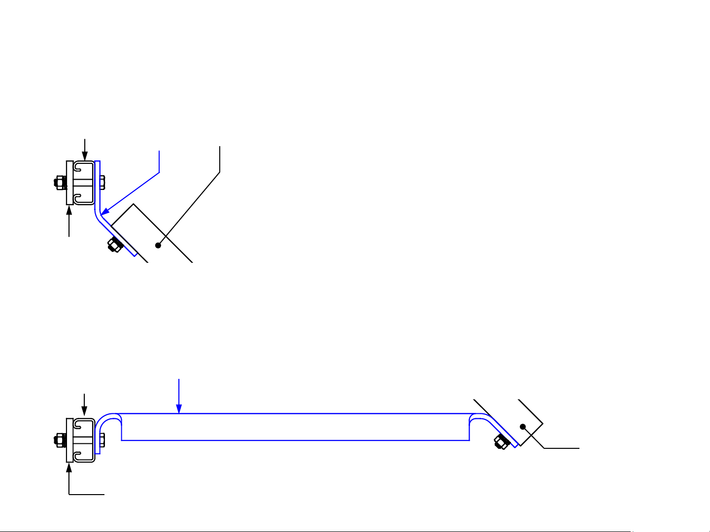
3) Attach one 1.5-foot-long Unistrut channel to the upper
mounting bracket with two ¼ -20 x 2” hex head bolts, square
Unistrut washers, lock washers, and nuts. See detail at left.
4) Attach two solar panel lower mounting brackets to the other
edge of the solar panel with two ¼-20 x 5/8” hex head bolts,
lock washers, and nuts. See detail below.
5) Attach the other ends of the two lower mounting brackets to
another 1.5-foot-long Unistrut channel with two ¼ -20 x 2” hex
head bolts, square Unistrut washers, lock washers, and nuts.
Support the assembly to avoid bending the solar panel frame.
Unistrut
channel
Upper
mounting
bracket
Solar
panel
Square
Unistrut
washer
Lower
mounting
bracket
Solar
panel
Unistrut
channel
Square
Unistrut
washer

2b. Attach the solar panel assembly to the pole.
6) Place the solar panel and frame assembly at the base of the
pole and facing South.
7) Attach a Unistrut clamp to the upper Unistrut channel and
around the pole, install the pole clamp bolt and nut, and
leave loose.
8) Attach a Unistrut clamp to the lower Unistrut channel and
around the pole, install the pole clamp bolt and nut, and
leave loose.
9) Slide the solar panel assembly up the pole to position the
upper Unistrut clamp at the 14” mark and the lower Unistrut
clamp at the 31” mark below the top of the pole. Support
the assembly to avoid bending the solar panel frame.
10) Ensure the panel is facing South; tighten the Unistrut clamps
to secure the solar panel to the pole.

3. Attach the SOOFIE enclosure to the pole.
1) Position the top of a Unistrut clamp at the 6.0” mark below
the top of the pole and insert into the upper Unistrut
channel on the SOOFIE enclosure. Slide the enclosure to the
side closest to the solar panel junction box and its wires.
2) Position another Unistrut clamp around the pole and insert
into the lower Unistrut channel on the SOOFIE enclosure.
3) Tighten both Unistrut clamps securely.

4. Power up the system and connect the cables.
1) Insert a 10A medium-blow fuse into a fuse receptacle cap;
push in firmly and turn clockwise to install in the left-hand
(battery) fuse receptacle. Confirm fuse cap is locked and
confirm audible fan operation. This fuse completes the
battery circuit; SOOFIE is now operating!
2) Insert the (+) and (–) connectors from the solar panel into
the MC4 receptacles on the SOOFIE enclosure. Confirm both
connectors are fully inserted and locked.
3) Insert a 10A medium-blow fuse into a fuse receptacle cap;
push in firmly and turn clockwise to install in the right-hand
(solar panel) fuse receptacle. Confirm fuse cap is engaged
and locked. This fuse completes the solar panel charging
circuit.
4) (if applicable) Insert the anemometer cable connector into
the M8 receptacle on the SOOFIE enclosure and rotate the
barrel on the cable connector until finger-tight.

Troubleshooting

1. Open the SOOFIE enclosure.
1) Loosen all 6 recessed cover screws and remove cover.
NOTE:
Cover screws are not captive; do not flip the cover over.
CAUTION:
High-current DC voltage up to 25v is exposed with cover off.

2. Check fusing and wiring.
NOTE:
The two fuses are interchangeable, but their removal/reinsertion
order is important. The solar panel fuse MUST be removed first
AND reinserted last, following the sequence below.
1) Remove the solar panel fuse from right-hand fuse holder by
pushing in firmly and turning counter-clockwise ½ turn;
ensure fuse is intact or replace with a new 10A 250V
medium-blow 1/4" x 1-1/4” glass cartridge fuse.
2) Remove the battery fuse from left-hand fuse holder by
pushing in firmly and turning counter-clockwise ½ turn;
ensure fuse is intact or replace with a new 10A 250V
medium-blow 1/4" x 1-1/4” glass cartridge fuse.
3) Reinsert the battery fuse into left-hand fuse holder.
4) Reinsert the solar panel fuse into right-hand fuse holder.
5) Confirm that all cables are firmly captured in MPPT solar
controller screw terminals.
6) Confirm that crimp terminals are fully engaged on battery
and fuse holder tabs.
7) Confirm that the MTA connectors on the sensor board are
properly seated.

3. Check and record voltages.
With a voltmeter, check and record DC voltages between:
1) Terminals on LiFePO4battery: vDC
2) BATT terminals on MPPT charge controller: vDC
3) PV terminals on MPPT charge controller: vDC
Note: PV terminal voltage will be zero unless the
solar panel is connected and exposed to the sun
4) LOAD terminals on MPPT charge controller: vDC

4. Check operation
1) Check that the intake fan is running.
2) Check the two LEDs on the MPPT solar charge controller:
a. Green LED on or blinking? (power from battery)
b. Yellow LED on or blinking? (charging from panel)
3) Check the status LED on the Particle Boron/Argon
microprocessor:
a. pulsing cyan? (connected to Internet)
b. blinking green? (looking for cellular/wifi service)
c. magenta? (firmware update in progress)
If these steps haven’t identified an obvious problem with an immediate solution,
please call Scientific Aviation technical support at (xxx) xxx-xxxx
Other manuals for SOOFIE
1
Table of contents
Popular Inverter manuals by other brands

WEG
WEG bacnet CFW701 Addendum to the programming and troubleshooting manual

Magnum Energy
Magnum Energy MagnaSine Hybrid Mobile Series owner's manual

Victron energy
Victron energy Quattro instruction manual

Sungrow
Sungrow SG3.0RT Quick installation guide

Rigol
Rigol DG952 user guide

Envertech
Envertech EVT2000 user manual