SCIFIT DC1000 Intelli-Fit User manual
Owner’s Manual
DC1000 Intelli-Fit Treadmill
SALES:
1-800-278-3933
CUSTOMER SERVICE:
1-800-745-1373
Order online 24/7 at www.SCIFIT.com
TM

This page purposely left blank

SCIFIT • Scientic Solutions for Fitness • SCIFIT • Scientic Solutions for Fitness • SCIFIT
Important Safety Instructions
Read all instructions before using your SCIFIT exercise machine!
Save these instructions!
Connect to a properly grounded outlet only. See Power Requirements
below. Also, always unplug this machine from the electrical outlet
immediately before cleaning and any servicing of the machine.
DANGER!
To minimize the risk of electric shock:
WARNING!
To reduce risk of burns, re, electric
shock, or injury to persons:
1. Close supervision is necessary when exercise machine is used
near children or disabled persons. Keep children away from
treadmill deck, especially when in operation.
2. Use the exercise machine only for its intended use as described
in this manual. Do not use attachments not recommended by
the manufacturer.
3. To make any adjustment during your workout, STOP the
machine and make the necessary adjustments.
4. Never operate the exercise machine if it has a damaged electrical
power cord or plug, if it is not working properly, or if it has been
damaged. Call the SCIFIT product support department for
further information about repair options.
5. Keep the electrical power cord away from heated surfaces, and
from the elevation mechanism.
6. Never operate the machine with the air openings blocked. Keep
the air openings free of lint, hair and other debris.
7. Never drop or insert any object into any opening.
8. Do not use outdoors.
9. Do not operate where aerosol (spray) products are being used
or in an oxygen rich environment.
10. To disconnect, turn o the power switch and unplug from the
wall outlet
SCIFIT • Scientic Solutions for Fitness • SCIFIT • Scientic Solutions for Fitness • SCIFIT
Important Safety Instructions
1. SCIFIT’s DC1000-INT(100-110V) treadmill requires a 110 Volt/ 15
AMP circuit. The circuit must have a minimum of 12 gauge wire.
Contact a qualied electrician to have one installed if needed.
Insucient power may cause your treadmill to function
improperly and will void the warranty.
2. DANGER: Improper connection of the equipment
grounding conductor can result in a risk of electric shock. Check
with a qualied electrician or serviceman if you are in doubt as
to whether the product is properly grounded. Do not modify
the plug provided with the product - if it will not t the outlet,
have a proper outlet installed by a qualied electrician
If you or your electrician have any questions, contact SCIFIT Product
Support at 1-800-745-1373.
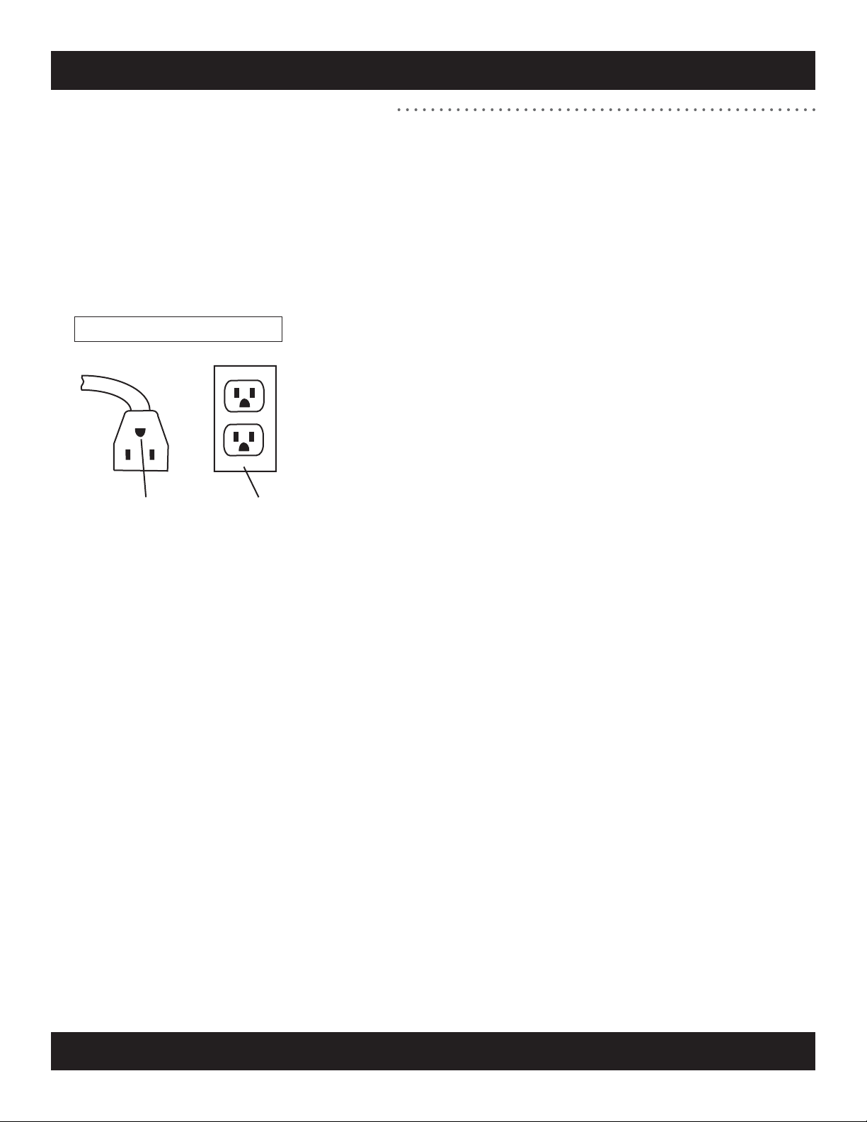
Power Requirements – DC1000-INT (100-110V)
Figure A: Grounded Outlet Diagram
Plug grounding
pin
Grounded outlet

Introduction
Installation and Maintenance
Heart Rate Transmitter Strap
Keypad Functions
Program Descriptions
Troubleshooting
Warranty Policy and Service Procedures
Warranty card
1.1 to 1.2
2.1
3.1 to 3.16
4.1 to 4.2
5.1
6.1 to 6.2
7.1 to 7.5
8.1 to 8.2
9.1
10.1 to 10.5
11.1
Table of Contents
Set-Up Mode
Product Components
Specications
Assembly
12.1

SCIFIT • Scientic Solutions for Fitness • SCIFIT • Scientic Solutions for Fitness • SCIFIT
Thank you for your purchase of the SCIFIT treadmill. We have incorporated
the nest technology and ergonomic design into this machine to assist you
in achieving your tness goals. However, for your safety, please adhere to
the following recommendations before you begin to exercise.
FITKEY™
Warm Up and Cool Down
Exercise at Your Own Level
Stay Within Your Target Heart Rate Zone
CAUTION: When To Stop Exercising
Train Intelligently
Consult Your Physician
Introduction 1.1
Your SCIFIT treadmill may be equipped with a FITKEY receptical. Contact
SCIFIT to learn more about this exercise protocol and documentation
software.
Consult your physician or medical specialist before participating in any
exercise program, especially if you are pregnant, or if you are suering
from: heart disease, respiratory disease, diabetes, hypertension, high
blood pressure, elevated cholesterol, arthritis or any other diseases or
physical complaints.
To prevent muscle injuries and soreness, you should always warm up
(at least 5 minutes) and cool down (at least 5 minutes) by doing a series
of stretches before and after each workout.
Increase your exercise level gradually, and avoid sudden, erratic,
or careless exercise. The key to a successful exercise program is
consistency.
For healthy beginners, start exercising two to four days a week with
your heart rate in the target zone for about twenty (20) minutes each
day.
Your approximate maximum heart rate (MHR) is equal to 220 minus
your age. The upper limit of your target zone is equal to 0.85 times
your MHR. The lower limit of your target zone is equal to 0.60 times
your MHR.
For example, if you are 40 years old, your approximate MHR is equal to
180 (220 minus 40). Therefore, your target zone is between 60% of 180
(0.60 x 180) = 108, and 85% of 180 (0.85 x 180) = 153. So for a 40 year
old, the target heart rate zone is between 108 and 153.
Try to stay within the target heart rate zone to achieve optimal tness
training. Avoid exceeding your maximum target heart rate as this
may cause stress, fatigue, and/or injuries to your body. At the same
time, you need to sustain the intensity level of your exercise above the
minimum target heart rate in order to achieve
Stop exercising immediately if you feel nausea, dizziness, sharp pain,
or any other physical discomfort. Do not resume until you consult with
a physician.
To ensure a future of good health, you should always eat well balanced
meals, drink plenty of uid/water during a workout, and stay t by
exercising intelligently.
SCIFIT • Scientic Solutions for Fitness • SCIFIT • Scientic Solutions for Fitness • SCIFIT
Introduction 1.2
• The safest position is with your feet on each top side cover,
straddling the running belt. Step onto the running belt after
you have started the treadmill to prevent injury.
• To balance yourself look straight ahead and hold on to the
side handlebars or front handlebar.
• It is common to feel slightly dizzy after getting o the treadmill
after a workout. This is because the ground has been moving
under you. To help avoid this, turn the treadmill down to a
slow speed and cool down for several minutes before getting
o.
• A treadmill is not for children to play on. Use common sense
when operating this treadmill and observe all caution stickers.
• Keep hand and ngers away from all areas that could cause
injury such as the front and back rollers.
• Never place rear of the treadmill near an obstruction.
• Never put any substance underneath the treadmill running
belt
• Do not spill any liquid on the treadmill running belt.
• Maximum user weight is 375 lbs/ 170 kg.
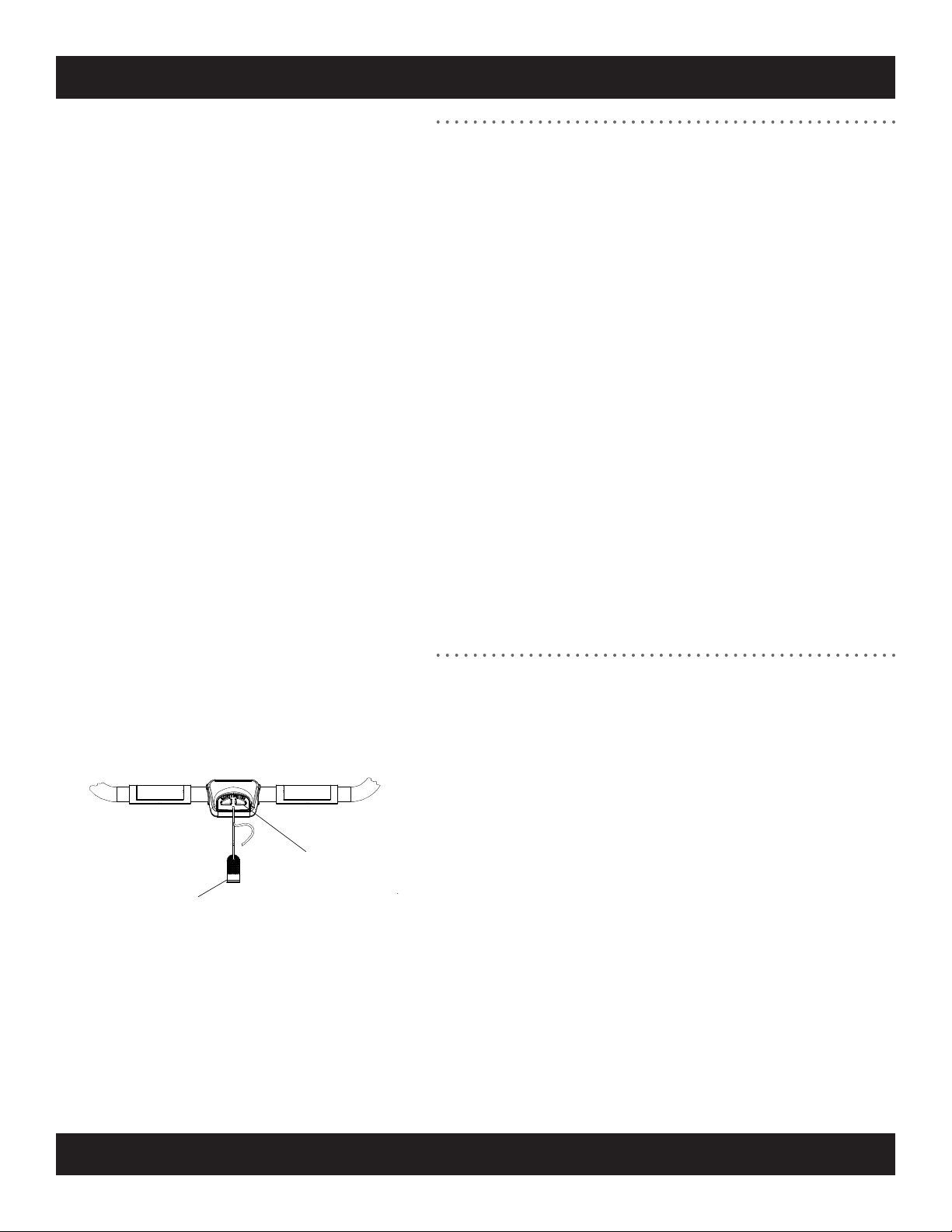
The Emergency Stop Magnet/Clip
• To stop the treadmill quickly in emergency situations pull the
magnet from the Emergency Stop housing.
Attach the Emergency Stop Clip to your clothing, in the front
chest area, using the Grip Teeth (see Figure to left) before
beginning your workout. If you should fall or slip backward
during the workout, the magnet will pull away from the
Emergency Stop housing and the running belt will come to a
rest
Safe Use of Treadmill
Emergency Stop Magnet is
located on the front handlebar
MAGNET
CLIP

SCIFIT • Scientic Solutions for Fitness • SCIFIT • Scientic Solutions for Fitness • SCIFIT
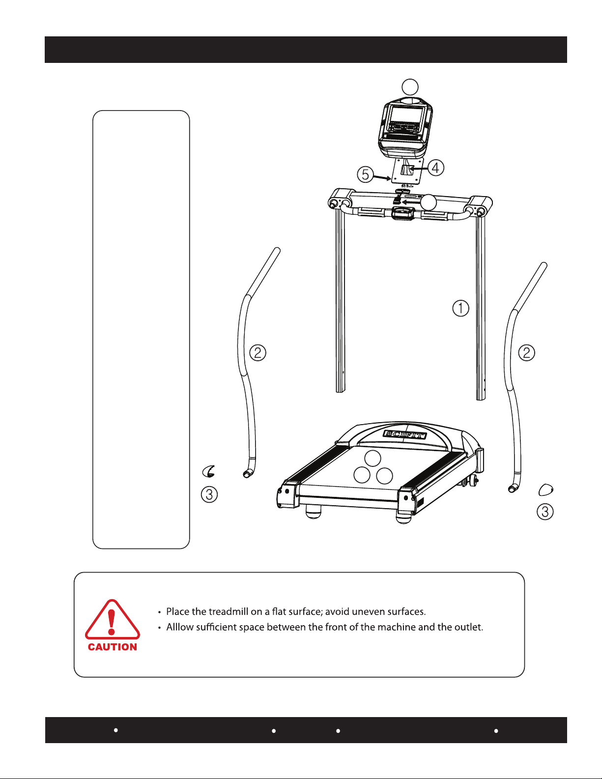
Product Components 2.1
1. External components
2. Internal components
Water Bottle Holder
LCD Intelli-Fit Console
Contact Heart Rate
Emergency Stop
Magnet/Clip
Easy Grip L & R
Side Handlebars
Non-Skid
Side Covers
L & R End Caps with
Walkbelt Alignment
Bolt Access
Motor Cover
Adjustable
Rear Feet
Walkbelt
LH & RH
Uprights
Drive
Belt
Front Roller
& Pulley
3hp Motor
110V Actuator
110V Motor
Controller Board
On/O
Power Switch
Thermal Fuse
AC Inlet
Transformer
Speed Sensor
Assembly
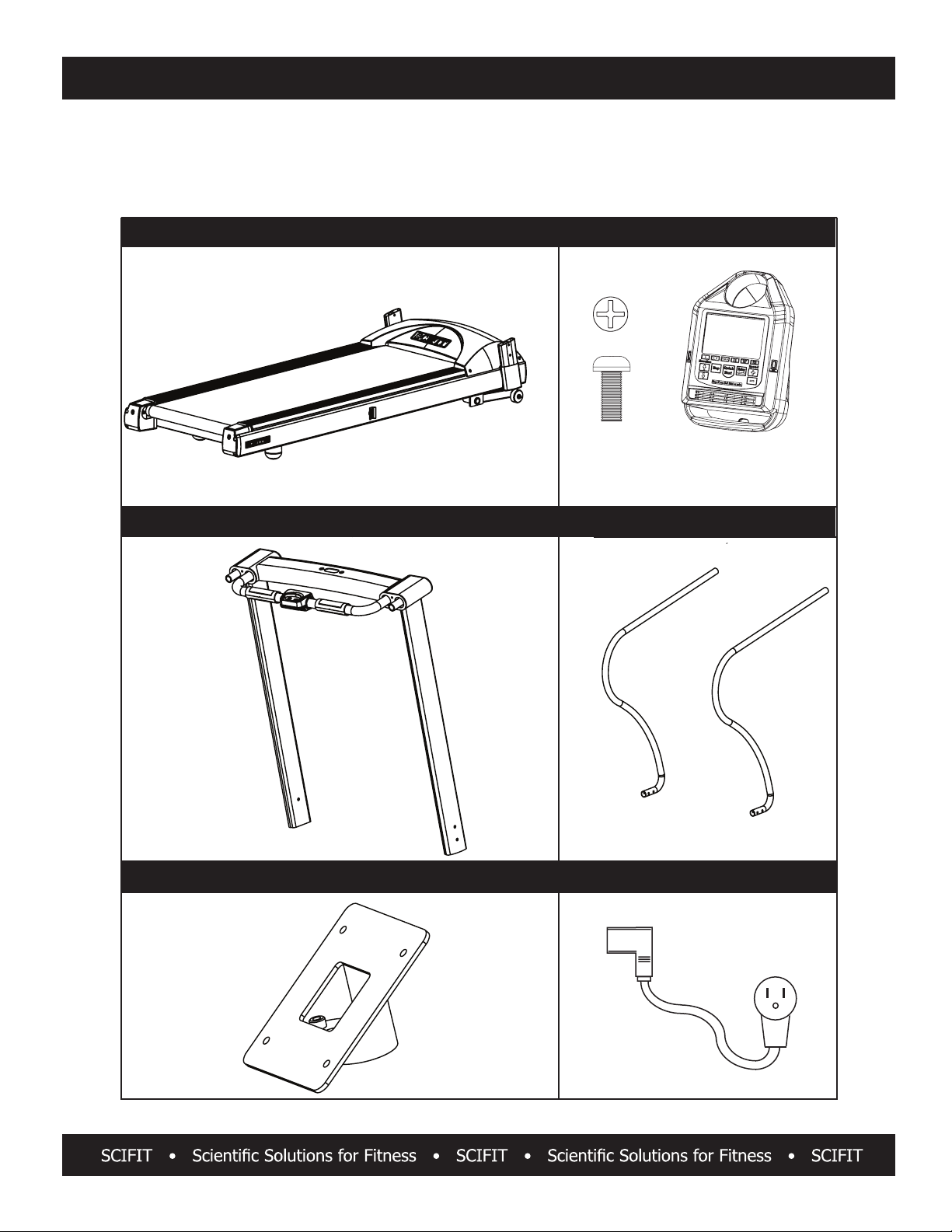
PARTS LIST
Please make sure all parts below are in the box before assembly.
Order online 24/7 at www.SCIFIT.com
NO
C
MAIN UNIT WITH MOTOR COVER
UPRIGHT WELDMENT ASSEMBLY
CONSOLE
SIDE HAND RAILS
POWER CORD
M5 x 12mm
Screw (Qty. 4) Console
CONSOLE MOUNT WELDMENT
3.1

PARTS LIST CONT’D
Please make sure all parts below are in the box before assembly.
Order online 24/7 at www.SCIFIT.com
MAGNET/CLIP LOWER SIDE RAIL COVERS
2-WIRE E-STOP CABLE
EXTENSION
4-WIRE CHR CABLE
EXTENSION
10-WIRE MAIN CABLE
EXTENSION
Assembly 3.2

Assembly
PARTS LIST CONT’D
ASSEMBLY BAG CONTAINING
M5 x 12mm
Screw (Qty. 2)
M8 Lock
Washer
(Qty. 6)
M8 Flat
Washer
(Qty. 6)
M6 T-Handle (Qty.1)
Order online 24/7 at www.SCIFIT.com
M8 x 16mm
w/Blue Loctite
Patch Screw
(Qty. 6)
M6 x 15mm
Screw (Qty. 4)
M8 x 50mm
Screw
(Qty. 2)
M8 x 45mm
Bolt
(Qty. 2)
M4 Hex Wrench
(Qty. 1)
M5 Hex Wrench
(Qty. 1)
Combination M6
Hex and Phillips
Wrench
(Qty. 1)
SCIFIT Scientific Solution for Fitness SCIFIT Scientic Solutions for Fitness SCIFIT
3.3
.
Assembly Procedures
Unpack
and assemble
as follows:
1. Install upright
weldment
2. Install side hand
rails
3. Attach lower side
hand rail covers
4. Attach cable
extensions to
console
5.
Attach console
mount weldment
to console
6. Attach console
w/weldment to
upright assembly
7. Attach magnet
and clip to the
machine
8. Power-Up
Assembly Note
• All power cables should be grounded.
• Verify dust and debris are removed from the machine before using.
Assembly 3.4
77
6
SCIFIT Scientific Solution for Fitness SCIFIT Scientic Solutions for Fitness SCIFIT
9. Belt Alignment
9
10
10. Belt Tension
11
11. Incline Calibration
Assembly 3.5
SCIFIT Scientic Solutions For Fitness SCIFIT Scientic Solutions For Fitness SCIFIT
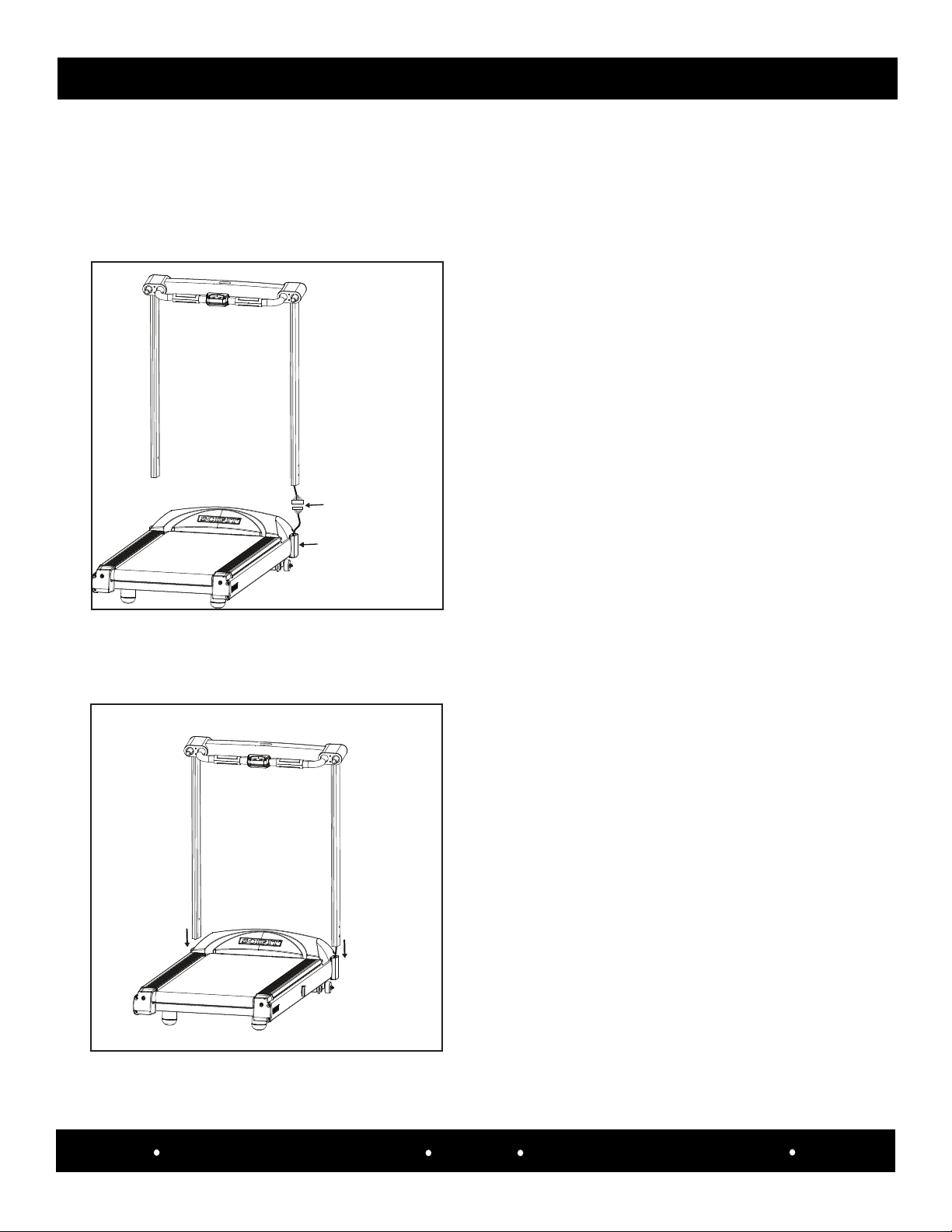
NOTE:
STEP 1: UPRIGHT WELDMENT INSTALLATION
1a. Carefully hold the upright weldment assembly over the
treadmill main body frame and attach the 10-wire connector
from the right upright to the 10-wire connector coming
from the treadmill main body frame upright extension.
1b. Push the connected cables back into the frame and
carefully slide the left and right uprights onto the frame
upright extensions of the main treadmill body.
.
3.4
1. The following assembly instructions for the DC1000 will require two people
2. Refer to section 3.3 for hardware indentication
.
3.4
Frame
Upright
Extension
Connect
Cables Here
SCIFIT Scientic Solutions For Fitness SCIFIT Scientic Solutions For Fitness SCIFIT
Assembly 3.6
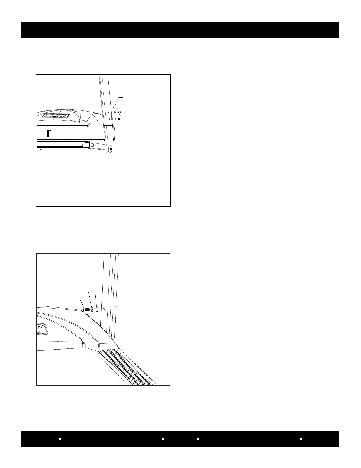
Hardware Required:
STEP 1: UPRIGHT WELDMENT INSTALLATION CONT’D
1f. Repeat steps 1c, 1d and 1e for the left upright. NOTE: The
screws will be secured properly in a later step.
(Qty. 2) M8 Split Washers
1c. Slide in order (Qty. 1) M8 Split washer, then (Qty. 1) M8 Flat
washer onto the rst M8 screw, then LOOSELY tighten the
screw into the upper mounting hole located on the outside
of the right upright with a M6 T-handle hex wrench. NOTE:
The screw will be secured properly in a later step.
(Qty. 2) M8 Flat Washers
(Qty. 2) M8 x 1.25 x 16mm Socket Button HD Screws
1d. Slide in order (Qty.1) M8 Split washer, then (Qty. 1) M8 Flat
washer onto the second M8 screw, then LOOSELY tighten the
screw into the lower mounting hole located on the outside of
the right upright with a M6 T-handle hex wrench as. NOTE:
The screw will be secured properly in a later step.
M8 Flat Washer
M8 Split Washer
M8 x 16mm Socket
HD Screw
Hardware Required:
(Qty. 1) M8 Split Washer
(Qty. 1) M8 Flat Washer
(Qty. 1) M8 x 1.25 x 16mm Socket Button HD Screw
M6 T-Handle Hex Wrench
Tool Required:
1e. Slide in order (Qty.1) M8 Split washer, then (Qty. 1) M8 Flat
washer onto the M8 screw, then LOOSELY tighten the screw
into the mounting hole located on the inside of the right
upright with a M6 T-handle hex wrench as shown. NOTE: The
screw will be secured properly in a later step.
M8 Flat Washer x 2
M8 Split Washer x 2
M8 x 16mm
Socket HD Screw x 2
Assembly 3.7
SCIFIT Scientic Solutions For Fitness SCIFIT Scientic Solutions For Fitness SCIFIT
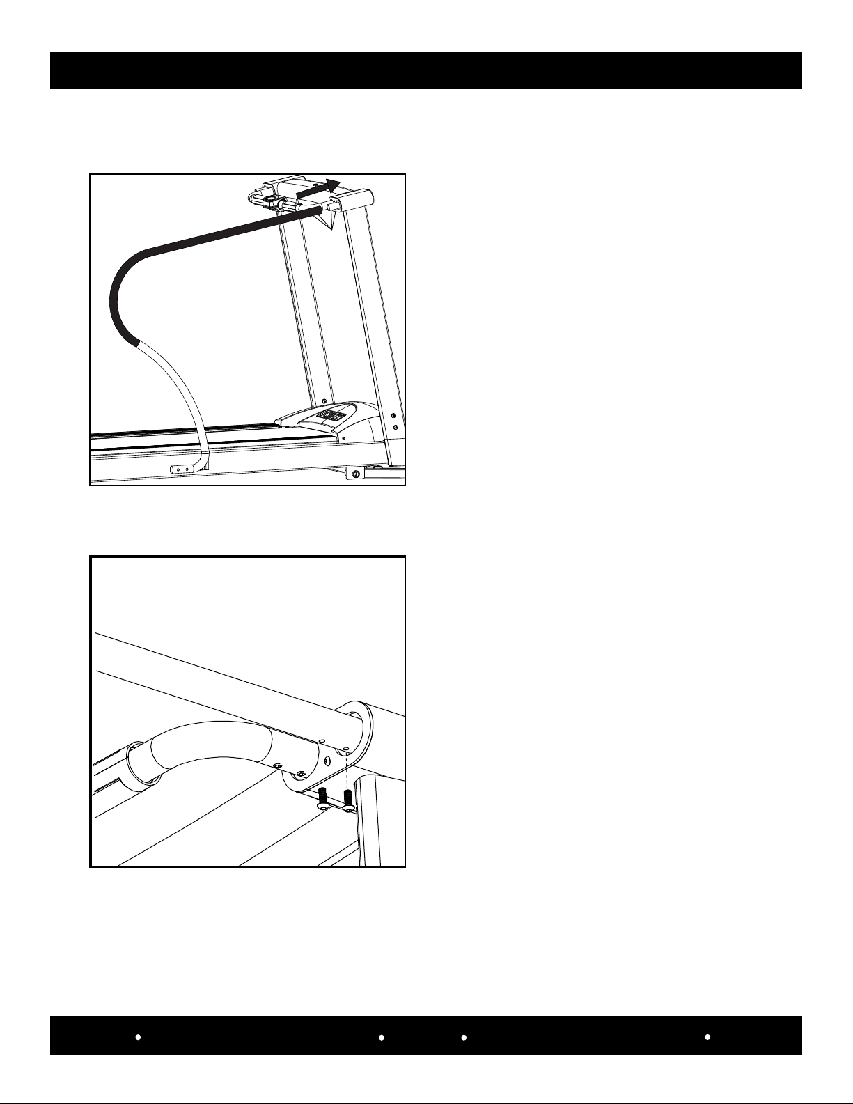
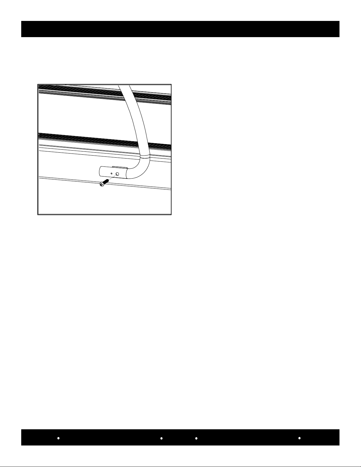
STEP 2: SIDE HAND RAIL INSTALLATION
2a. Starting on the right side, take one of the side hand rails
and slide the upper end (has two holes on bottom side of
tube) onto the extended tube coming from the upright
weldment and align the holes of the hand rail with the holes
of the tube extension from the upright.
Align
Holes
(Qty. 2) M6 x 1.0 x 15mm
Socket Button HD Screws
M4 Hex Wrench
2b. Use a M4 Hex wrench to LOOSELY secure the hand rail
with (Qty.2) M6 x 15mm socket button head screws.
Tool Required: Hardware Required:
SCIFIT Scientic Solutions For Fitness SCIFIT Scientic Solutions For Fitness SCIFIT
Assembly 3.8
2c. Align the larger screw hole of the lower side hand rail
with the hole of the frame mounting bracket, then use a M5
hex wrench to LOOSELY attach a M8 x 50mm socket button
head screw .
Tool Required: Hardware Required:
M5 Hex Wrench (Qty. 1) M8 x 1.25 x 50mm
Socket Button HD Screw
2d. Repeat steps 2a, 2b and 2c for the left side.
2e. Return to the screws attaching the lower part of the upright
weldment assembly from step 1 and using a M6 T-handle hex wrench
tightly secure the three screws on both the right and left uprights.
2f. Using a M4 hex wrench tightly secure the two screws on
both the upper right and left side hand rails .
2f. Using a M5 hex wrench tightly secure the screw on both the
lower right and left side hand rails .
STEP 2: SIDE HAND RAIL INSTALLATION CONT’D
Assembly 3.9
SCIFIT Scientic Solutions For Fitness SCIFIT Scientic Solutions For Fitness SCIFIT
4a. Place the console face down on a at surface.
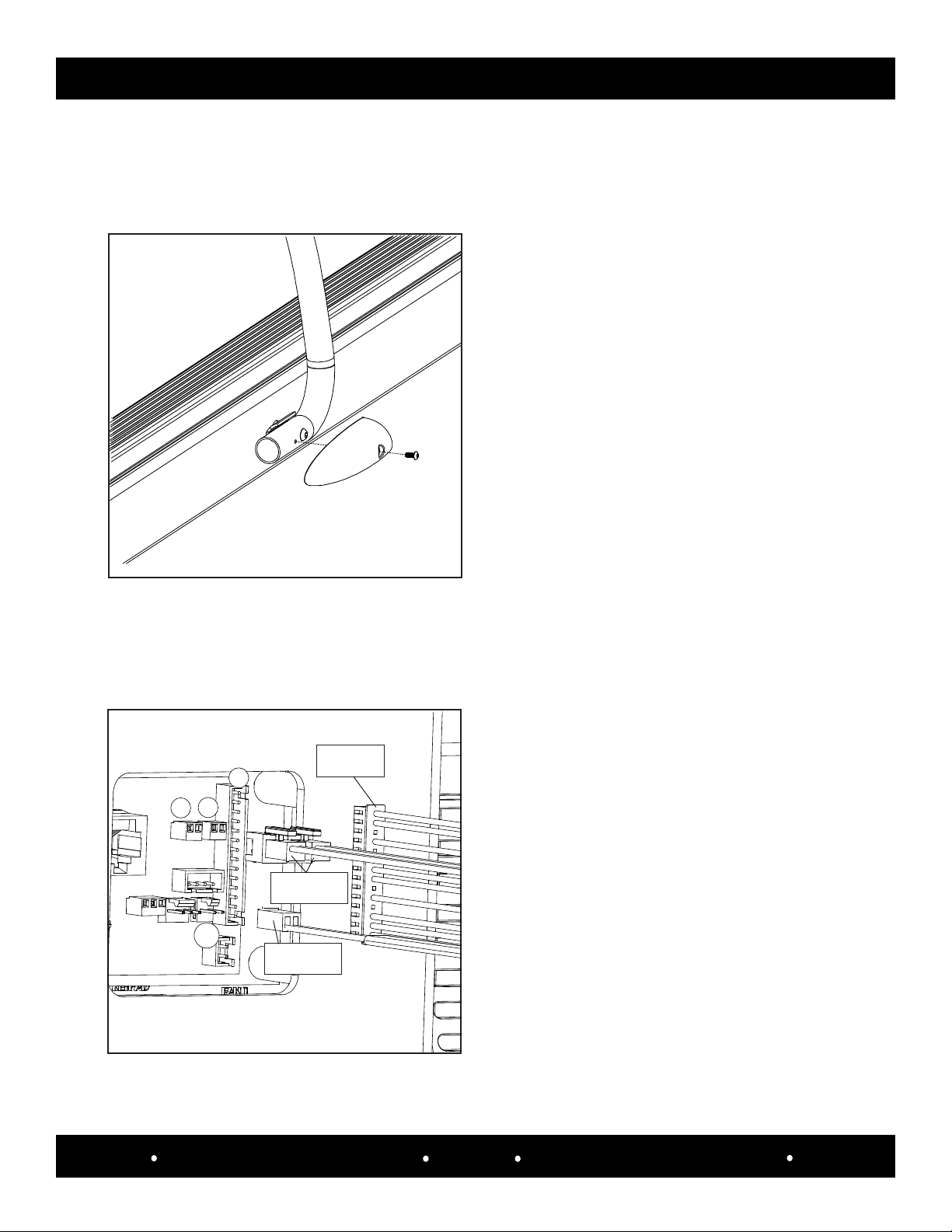
STEP 3: ATTACH LOWER SIDE HAND RAIL COVERS
3a. Starting on the right side take the rst of the two lower
side hand rail covers and align the cover screw hole with
lower side hand rail screw hole, then using the phillips end
of the combo wrench and secure the cover with a M5 x
12mm Phillips screw.
Tool Required: Hardware Required:
M6/Phillips combo hex
wrench
(Qty.1) M5 x .8 x 12mm
Phillips HD Screw
3b. Repeat step 3a for the left side.
STEP 4: ATTACH CABLE EXTENSIONS TO CONSOLE (See section 3.2 for cable identication)
Cables Required:
(Qty.1) 10 wire MAIN cable
(Qty.1) Dual 2 wire CHR cable
(Qty.1) 2 wire E-STOP cable
4b. Looking in from the rear of the console, attach the 10
wire female end of the main cable to connector P1 .
4c. Attach the Dual 2 wire CHR (Dual male housing end)
cable to connectors P3 and P4.
4d. Attach the 2 wire E-Stop cable to connector P11.
10 - Wire
Main Cable
Dual 2 - Wire
CHR Cable
P4
P3
P1
P11
2 - Wire
E-Stop Cable
Assembly 3.10
SCIFIT Scientic Solutions For Fitness SCIFIT Scientic Solutions For Fitness SCIFIT
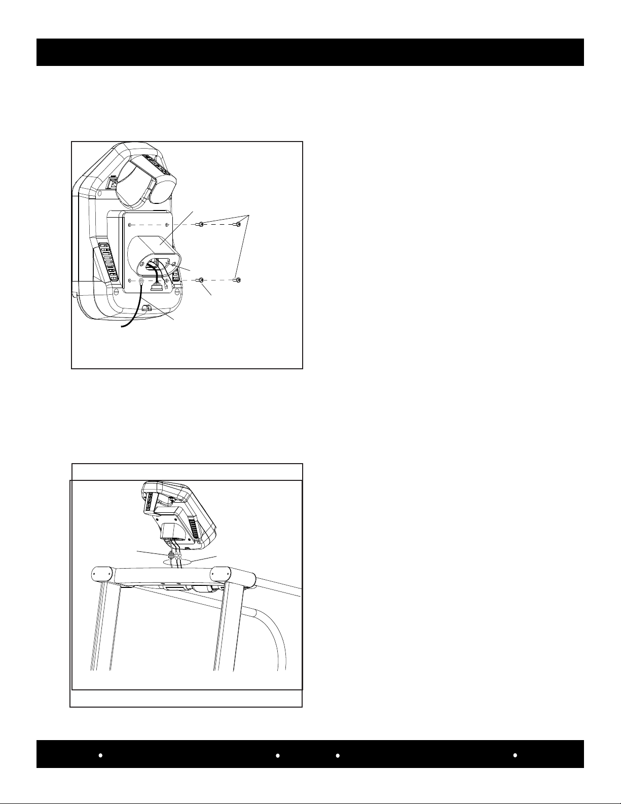
5b. Route the Main, CHR and E-Stop cables through the
exit hole on the console mounting bracket, then align the
mounting bracket holes with the console mounting holes .
Tool Required: Hardware Required:
Phillips screw driver(Qty. 4) M5 x .8 x 12mm
Phillips HD Screw
5c. Take the ring lug end of the Magnet/Clip tether and
using a phillips screw driver secure it to the lower left corner
of the console mount weldment with (Qty. 1) M5 x 12mm of
the screws previously removed in step 5a .
6a. Pull out the Main, CHR and E-Stop cables from the
machine center frame and connect them to the Main, CHR
and E-Stop extension cables coming from the console.
6b. After connecting, push all the cables back into the
center frame and align the two console mounting bracket
holes with the two center frame mounting holes..
STEP 5: ATTACH THE CONSOLE MOUNT WELDMENT TO CONSOLE
5a. Remove the four screws that are inserted into the rear
enclosure of the console and place to the side.
STEP 6: ATTACH CONSOLE WITH MOUNTING BRACKET TO THE UPRIGHT ASSEMBLY
5d. Using a phillips screw driver nish securing the console
mount weldment with (Qty. 3) M5 x 12mm phillips head
screws previously removed in step 5a.
Pull cables out
from center frame
Connect cables here,
then push them into
the center frame
Console
Mounting
Bracket
M5 x 12mm Screw
To Secure Ring Lug
Exit Hole
Magnet/Clip
Ring Lug
Secure Console
Mount With
Remaining
M5 x 12mm
Screws
SCIFIT Scientic Solutions For Fitness SCIFIT Scientic Solutions For Fitness SCIFIT
Assembly 3.11
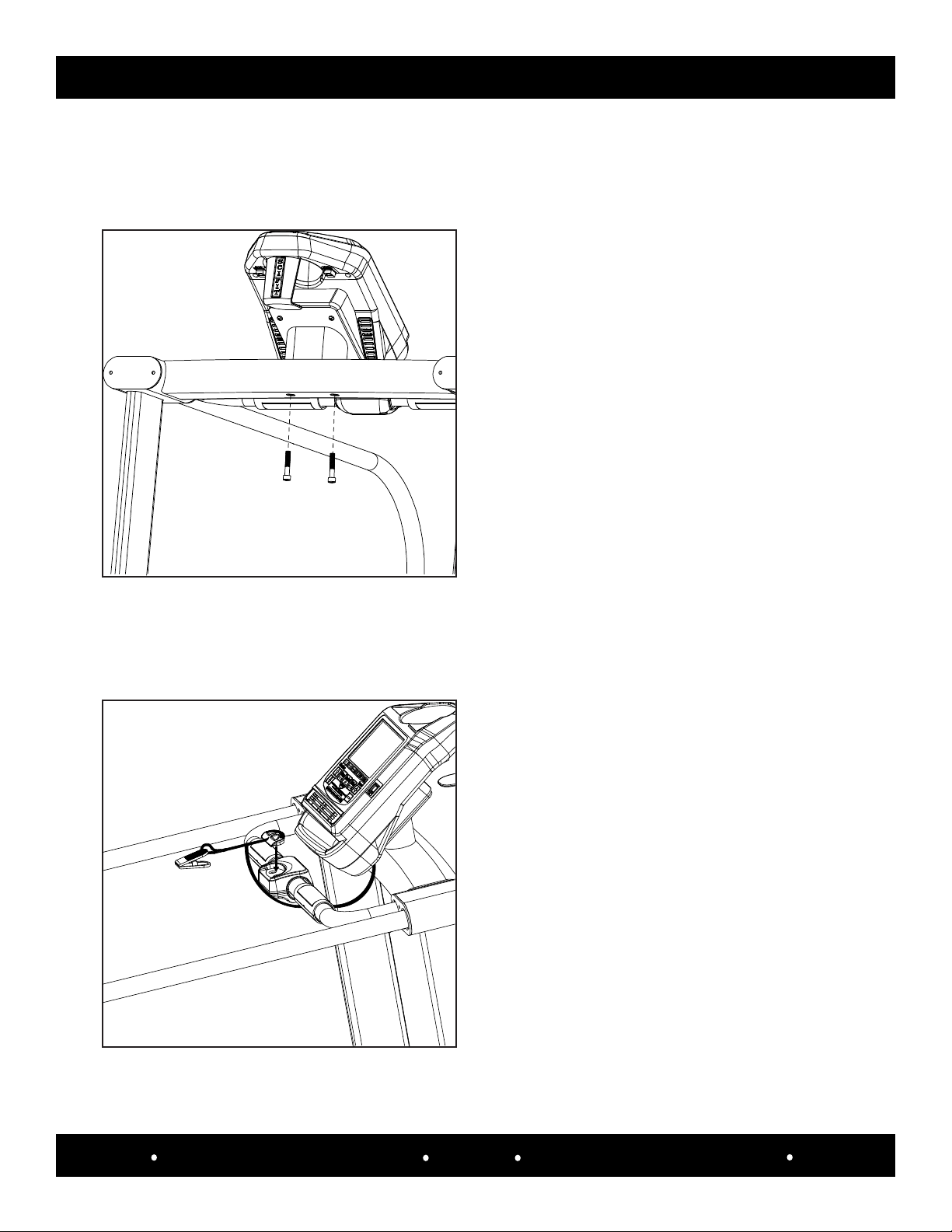
STEP 6: ATTACH CONSOLE WITH MOUNTING BRACKET TO THE UPRIGHT ASSEMBLY CONT’D
Tool Required: Hardware Required:
M6 T-handle wrench(Qty. 2) M8 x 1.25 x 45mm
Socket Cap HD screws
6c. After aligning the console mount weldment holes with
the center frame mounting holes, use a M6 T-handle and
(Qty. 2) M8 x 45mm socket cap screws to secure it in place.
STEP 7: ATTACH MAGNET AND CLIP TO THE MACHINE
Part Required:
(Qty. 1) Magnet/Clip
7a. Place the magnet end of the tether onto the Emergency
stop housing.
Assembly 3.12
SCIFIT Scientic Solutions For Fitness SCIFIT Scientic Solutions For Fitness SCIFIT
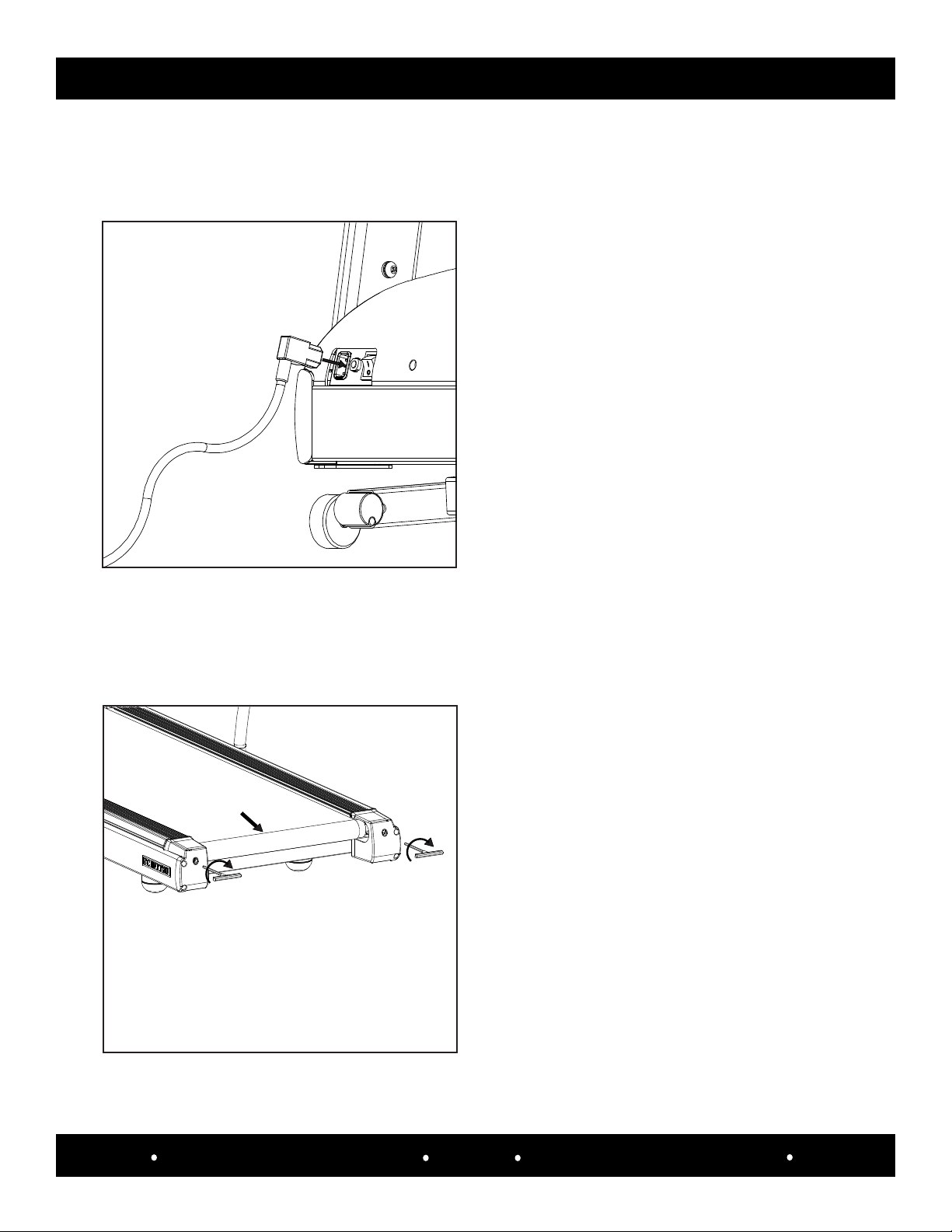
STEP 8: POWER-UP
Part Required:
(Qty. 1) AC Power Cord
8a. Verify the On/O switch is in the “OFF” position, then
plug in the right angle end of the AC power cord into the AC
power inlet located at the front of the machine.
8b. Plug the other end of the AC power cord into the wall
outlet, then ip the On/O switch to the “ON” position and
the console turn on .
STEP 9: BELT ALIGNMENT AND TENSION
Tool Required:
M6 T-Handle Wrench
Clockwise
Tightens Belt
Clockwise
NOTE: If belt had been replaced begin at step 9a.
If you are just making making minor adjustments
begin at step 9c.
9a. Center the walkbelt manually between the side covers.
9b. Insert an M6 T-Handle wrench into the right end cap
and turn the handle clockwise, then place the T-handle
into the left end cap and equally turn the handle clockwise.
Continue doing this until the walk belt becomes taunt
Other manuals for DC1000 Intelli-Fit
1
Table of contents
Other SCIFIT Treadmill manuals


