SCIFIT AC5000 series User manual

Operations Manual
AC5000/AC5000M Intelli-Fit Treadmills
SALES:
800-278-3933
CUSTOMER SERVICE:
800-745-1373 or 918-359-2040
www.SCIFIT.com
Order online 24/7 at www.SCIFIT.com

This page purposely left blank

SCIFIT SCIFIT SCIFITSCIFIT
Important Safety Instructions
Read all instructions before using your SCIFIT exercise machine!
Save these instructions!
DANGER!
To minimize risk of electric shock:
Connect to a dedicated, properly grounded outlet only. See Power
Requirements below. Also, always unplug this machine from the
electtrical outlet immediately after using and before cleaning.
WARNING!
To reduce risk of burns, 1. Close supervision is necessary when exercise machine is used
by or near children or disabled persons. Keep children away
from treadmill deck, especially when in operation.
2. Use the exercise machine only for its intended use as described
in this manual. Do not use attachments not recommended by the
manufacturer.
3. To make any adjustment during your workout, STOP the machine
and make the necessary adjustments.
4. Never operate the exercise machine if it has a damaged electrical
power cord or plug, if it is not working properly, or if it has been
damaged. Call the dealer the exercise machine was purchased
from for further information about repair options.
4. Keep the electrical/power cord away from heated surfaces, and
from the elevation mechanism.
5. Never operate the machine with the air openings blocked. Keep
the air openings free of lint, hair and other debris.
6. Never drop or insert any object into any opening.
7. Do not use outdoors.
8. Do not operate where aerosol (spray) products are being used or
in an oxygen rich environment.

Directives de sécurité importantes
DANGER !
AVERTISSEMENT !

SCIFIT SCIFIT SCIFIT SCIFIT
Important Safety Instructions
Power Requirements – AC5000 and
AC5000M (220V) 1. SCIFIT’s AC5000 and AC5000M treadmill requires a 208-265 Volt
10 AMP dedicated circuit. The circuit must have a minimum
of 12 gauge wire. A dedicated circuit is a power outlet reserved
for the exclusive use of your treadmill. This requires a power
line to be routed from the main breaker box or subpanel to the
power outlet for the treadmill.The outlet should not be shared
with any other piece of equipment. Isolated grounds are highly
recommended. If you have not previously arranged for such an
An
improperly and will void the warranty.
2. DANGER:
Improper connection of the equipment-
grounding conductor can result in a risk of electric shock. Check
with
to whether the product is properly grounded. Do not modify the
plugprovided with the product - if it will not t the outlet, have a
If you or your electrician have any questions, contact SCIFIT Product
Support at 800-745-1373 or 918-359-2040.
Power Requirements – AC5000 and 1. SCIFIT’s AC5000 and AC5000M (100-110V)treadmill requires
a 120 Volt/ 15 AMP dedicated circuit.The circuit must have a
minimum of 12 gauge wire. A dedicated circuit is a power outlet
reserved for the exclusive use of your treadmill. This requires a
power line to be routed from the main breaker box or subpanel
to the power outlet for the treadmill.The outlet should not be
shared with any other piece of equipment.If you have not pre-
to have one installed.
your treadmill to function improperly and will void the warranty.
2.
grounding conductor can result in a risk of electric shock. Check
whether the product is properly grounded.Do not modify the
plug outlet, have
If you or your electrician have any questions, contact SCIFIT Product
Support at 800-745-1373 or 918-359-2040.
AC5000M (100 -110V)
Figure A: Grounded Outlet Diagram
Grounded outlet
Plug grounding
pin
DANGER: Improper connection of the equipment-
a qualied electrician or serviceman if you are in doubt as
with a qualied electrician or serviceman if you are in doubt as to
a

SCIFIT SCIFIT SCIFITSCIFIT
Directives de sécurité importantes
Alimentation requise – 5000 CA (220 V)
et 5000M (220V) 1. Les tapis roulants5000 CA et (220 V) exigent uncircuit spécialisé
de 208-265 volts, 10A ayant un calibre minimal de 12 . Par circuit
spécialisé, on entend une prise réservée pour l’usage exclusif du
cipal des disjoncteurs ou du panneau secondaire jusqu’à la prise
du tapis. Aucun autre dispositif ne doit être branché sur la prise. On
recommande par ailleurs fortement une mise à la terre isolée. Si
une telle prise n’est pas déjà à sa disposition, on doit contacter
tionnement du tapis et annuler la garantie.
2. DANGER:
un raccordement inadéquat du conducteur de
terre de l’appareil peut causer un choc électrique. En cas de doute
concernant la mise à la terre correcte de l’appareil, consulter
un électricien ou technicien. fournie avec
l’appareil ; si elle ne convient pas à la prise, demander à un élec
L’acheteur ou l’électricien peut adresser toute question au service
d’assistance de SCIFIT en appelant le (aux Etats-Unis) (918) 359-2040,
(800) 745-1373 or 918-359-2040.
Alimentation requise – 5000 CA (110V) 1. Les tapis roulants 5000 CA (100-110 V) exigent uncircuit spécialisé
de 120 volts, 15A ayant un calibre minimal de 12 . Par circuit spécial
isé, on entend une prise réservée pour l’usage exclusif du tapis. Il
faut donc acheminer une ligne électrique du boîtier principal des
disjoncteurs ou du panneau secondaire jusqu’à la prise du tapis.
Aucun autre dispositif ne doit être branché sur la prise. Si une telle
prise n’est pas déjà à sa disposition, on doit contacter un élec
du tapis et annuler la garantie.
2.
terre de l’appareil peut causer un choc électrique. En cas de doute
concernant la mise à la terre correcte de l’appareil, consulter
un électricien ou technicien. fournie avec
l’appareil ; si elle ne convient pas à la prise, demander à un élec
L’acheteur ou l’électricien peut adresser toute question au service
d’assistance de SCIFIT en appelant le (aux Etats-Unis) (918) 359-2040,
(800)745-1373 or 918-359-2040.
Figure A : diagramme de la prise mise à
la terre
BROCHE
(TERRE)
BOITIER DE
PRISE
et
5000M CA (100-110V)
tapis. Il faut donc acheminer une ligne électrique du boîtier prin
DANGER: un raccordement inadéquat du conducteur de

SCIFIT SCIFIT SCIFIT SCIFIT
Table of Contents
Introduction 1.1 to 1.2
Product Components 2.1
Assembly 3.1 to 3.8
Installation and Maintenance 4.1 to 4.2
5.1
Warranty card 11.1
Heart Rate Transmitter Strap
Program Descriptions 7.1 to 7.5
Keypad Functions 6.1 to 6.2
Specifications 10.1 to 10.2
Troubleshooting 8.1
Warranty Policy and Service Procedures 9.1 to 9.5

SCIFIT SCIFIT SCIFIT SCIFIT
Introduction 1.1
Thank you for your purchase of the SCIFIT treadmill. We have incorporated
machine to assist you
afety, please adhere to
the following recommendations before you begin to exercise.
FITKEY™
Consult Your Physician gnitapicitraperofebtsilaicepslacidem
ronaicisyhpruoytlusnoC
in any exercise program, especially if you are pregnant, or if you
hypertension, high blood pressure, elevated cholesterol, arthritis,
or any other diseases or physical complaints.
Warm Up and Cool Down mrawsyawladluohsuoy,ssenerosdnaseirujnielcsumtneverpoT
up (at least 5 minutes) and cool down (at least 5 minutes) by
doing a series of stretches before and after each workout.
Exercise at Your Own Level ,citarre,neddusdiovadna,yllaudarglevelesicrexeruoyesaercnI
or careless exercise. The key to a successful exercise program is
consistency.
Stay Within Your Target Heart Rate Zone For healthy beginners, start exercising two to four days a week
with your heart rate in the target zone for about twenty (20) min
utes each day.
Your approximate maximum heart rate (MHR) is equal to 220
minus your age. The upper limit of your target zone is equal to
0.85 times your MHR. The lower limit of your target zone is equal
to 0.60 times your MHR.
For example, if you are 40 years old, your approximate MHR
is equal to 180 (220 minus 40). Therefore, your target zone is
between 60% of 180 (0.60 x 180) = 108, and 85% of 180 (0.85
x 180) = 153. So for a 40 year old, the target heart rate zone is
between 108 and 153.
-
ness training. Avoid exceeding your maximum target heart rate
as this may cause stress, fatigue, and/or injuries to your body.
At the same time, you need to sustain the intensity level of your
exercise above the minimum target heart rate in order to achieve
CAUTION: When To Stop Exercising Stop exercising immediately if you feel nausea, dizziness, sharp
uoylitnuemusertonoD.trofmocsidlacisyhprehtoynaro,niap
consult with a physician.
Train Intelligently llewtaesyawladluohsuoy,htlaehdoogfoerutufaerusneoT
Your SCIFIT treadmill may be equipped with a FITKEY receptical.
Contact SCIFIT to learn more about this exercise protocol and
documentation software.

SCIFIT SCIFITSCIFITSCIFIT
Introduction 1.2
Safe Use of TreadmillThe safest position is with your feet on each top side frame,
straddling the running belt. Step onto the running belt after
you have started the treadmill to prevent injury.
To balance yourself look straight ahead and hold on to the
side rails or handlebar.
It is common to feel slightly dizzy after getting o the
treadmill after a workout. This is because the ground has be
been moving under you. To help avoid this, turn the treadmill
down to a slow speed and cool down for several minutes
before getting o.
A treadmill is not for children to play on. Use common sense
when operating this treadmill and observe all caution stickers.
ld cause
injury such as the front and back rollers.
Never place rear of the treadmill near an obstruction.
Never put any substance underneath the treadmill running
Do not spillany liquid on the treadmill running belt.
Maximum user weight is 550 pounds (250kg).
The unique Emergency Stop Push button/Pull magnet can be
activated in one of two ways:
Energency Stop Button/Magnet
located on center handlebar
To stop the treadmill quickly in emergency situations by
pulling the magnet from the control panel.
Attach the Emergency Stop Clip to your clothing, in the front
chest area, using the Grip Teeth (see Figure to left) before
beginning your workout. If you should fall or slip backward
during the workout, the magnet will pull away from the
control panel and the running belt will come to a rest.
CLIP Pull magnet
Lanyard option
(Push Button option)The Pull Magnetoption:
The Push Buttonoption
To stop the treadmill quickly in emergency situations you may
the belt will come to a rest.
belt.
also push the emergency button (see gure to the left) and
SCIFIT SCIFIT SCIFITSCIFIT
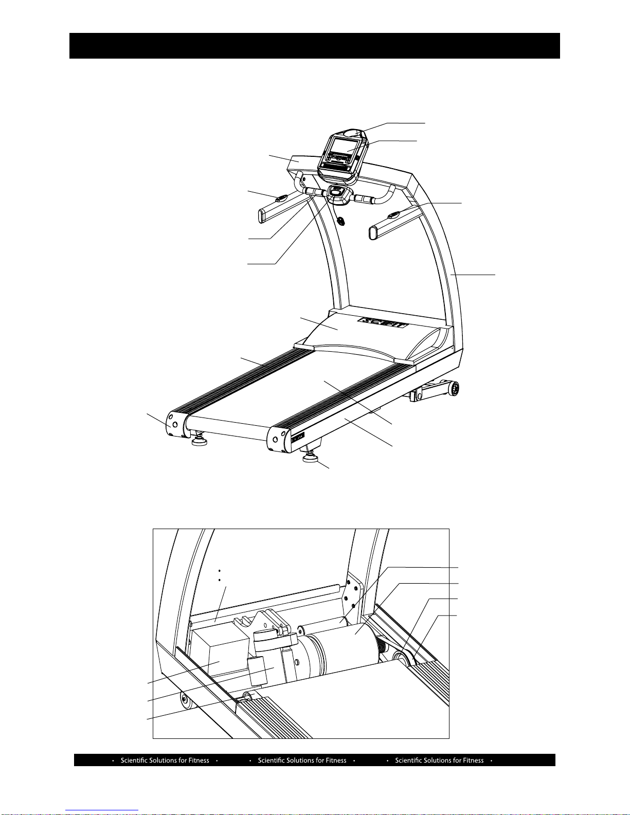
Product Components 2.1
2. Internal components
1. External components
Liquid Crystal Display Console
Water Bottle Holder
Speed Switch
LH & RH
Upright Frames
Running Belt
Main Frame
Leveling Pad
Center Weldment
Incline Switch
Contact Heart Rate
Emergency Stop
Motor Cover
Side Rails
LH & RH
End Caps
Power Resistor
Main Motor
Front Roller Pulley
Drive Belt
Front Roller
Actuator Motor
Inverter
Components located
behind the inveter:
Combination Inlet & Breaker
Noise Filter
SCIFIT SCIFIT SCIFITSCIFIT
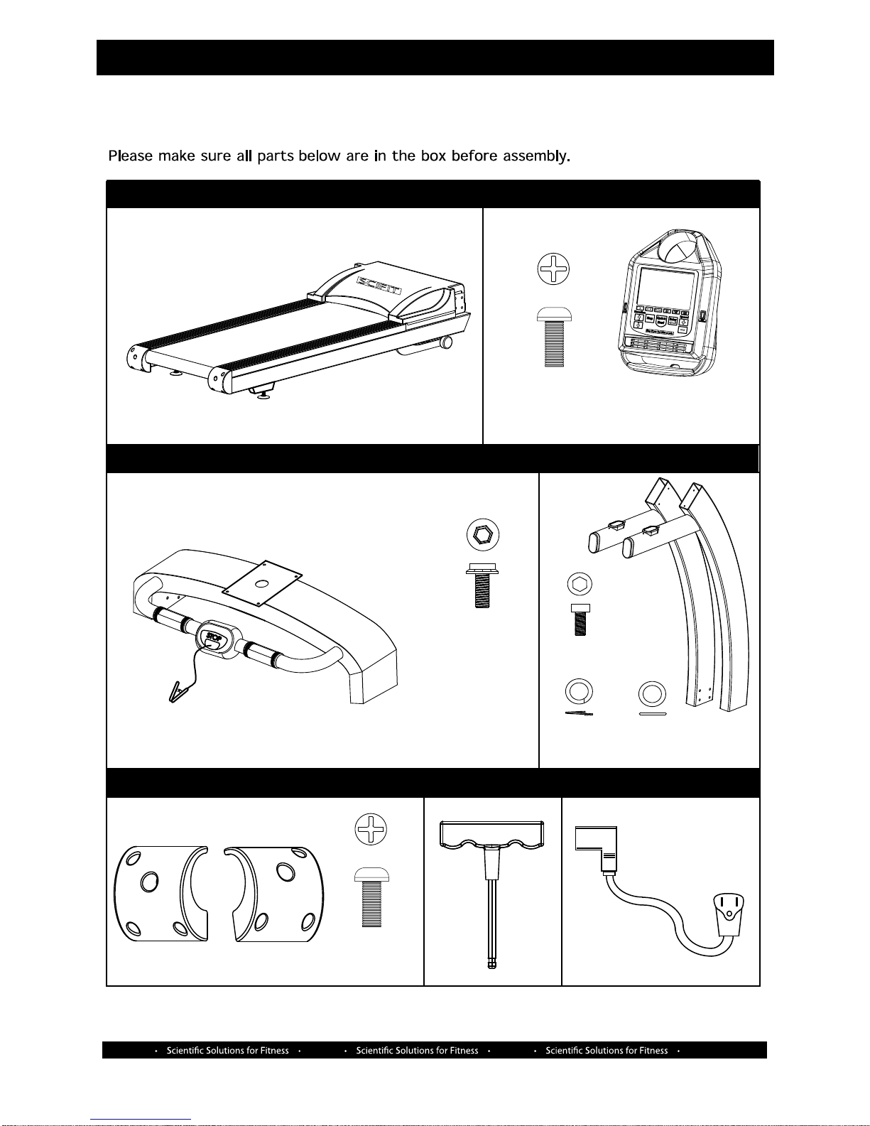
Assembly 3.1
PARTS LIST
ELOSNOCMAIN UNIT WITH MOTOR COVER
M5 x 12mm
Screw (Qty. 4) Console
CENTER FRAME LH/RH UPRIGHTS
POWER CORD
M10 x 20mm
Screw (Qty. 4)
M12 Lock
Washer
(Qty. 8)
M12 Flat
Washer
(Qty. 8)
M12 x 30mm
Screw (Qty. 8)
SCIFIT
5/16 T-HANDLE
Order online 24/7 at www.SCIFIT.com
M5 x 12mm
Screw (Qty. 6)
LH/RH END CAPS
SCIFIT SCIFIT SCIFITSCIFIT
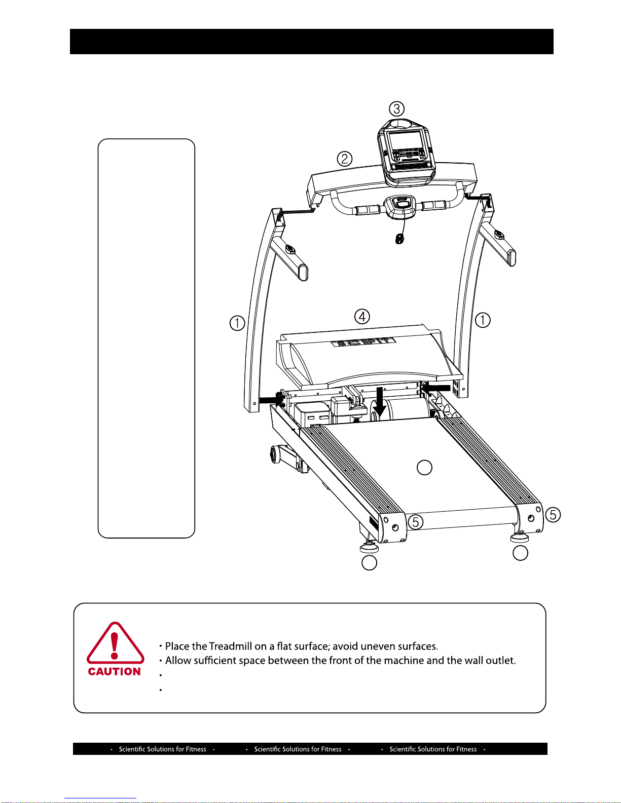
Assembly 3.2
Upack the carton,
assemble as
follows:
1. Install left and
right Uprights
2. Install center
weldment
3. Install console
to center
weldment
4. Install motor
cover
5.
Level pads
6.
Connect
power cord
(not shown)
7.
Align
running belt
Assembly Procedures
Assembly Note
All power cables should be grounded.
Verify dust and debris are removed from the machine before using.
8
End Caps
8.
66
SCIFIT SCIFIT SCIFITSCIFIT
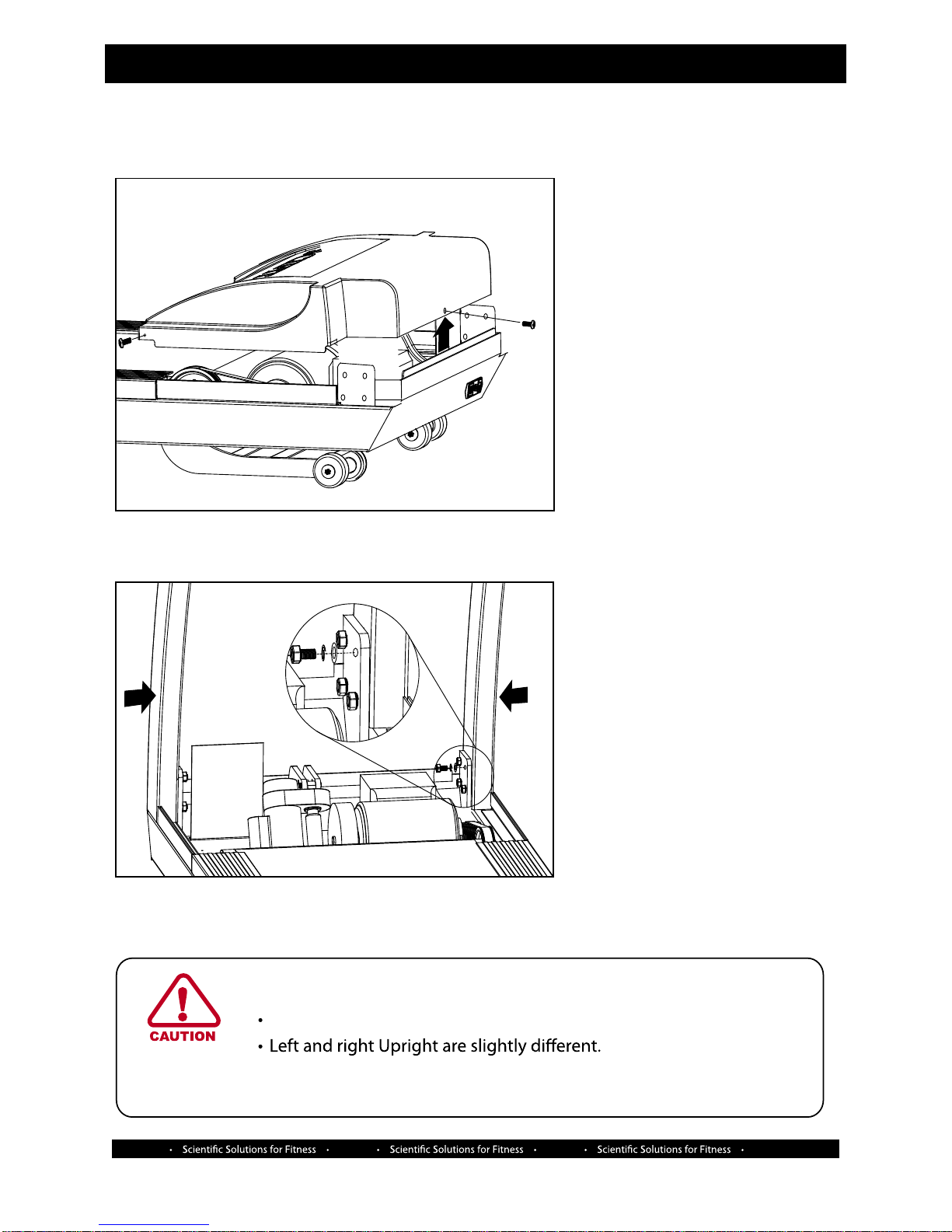
Assembly 3.3
1. Install LH/RH Uprights
STEP 1 - Using a phillips
screw driver remove the three
screws (2 on the side, 1 in the front)
securing the motor cover, then
place the cover to the side.
STEP 2 - Align the holes of the
right upright to the holes on the
upright mounting plate of the
frame, then with a 10mm Hex bit
loosely secure with the upright
with (Qty. 4) M12 Flat washers,
(Qty. 4) M12 Lock washers
and (Qty. 4) M12 x 30mm Screws
STEP 3 - Connect the internal
communication RJ45 cable of the
left upright to the communication
cable coming from the main frame
before repeating STEP 2 for the
left side.
CAUTION
Fasten hardware securely to eliminate noise due to looseness
- The left Upright has a small cut-out at the bottom to allow for
cable routing.
SCIFIT SCIFIT SCIFIT SCIFIT
Assembly 3.4
STEP 1- Carefully lay the center weldment on the uprights and connect the Speed cable from the
center weldment to the Speed cable coming from the right upright.
Then connect the Incline and Communication cables of the weldment to the left upright cables.
STEP 2- Align the holes of the center weldment with the holes of the left and right uprights.
Using a 9/16 socket begin with the left side and loosely attach (Qty. 2) M10 x 20mm screws.
Repeat the same process for the right upright.
NOTE: Be careful not to pinch the cables inside the uprights.
When all bolts are attached, then securely tighten.
At this time return to the bolts securing the LH/RH uprights and firmly tighten them.
Incline
3-pin female
Speed
3-pin male
E-stop
2-pin female
2. Install Center Weldment
CHR
2-pin male
CHR
2-pin male
Communication
RJ45
Speed
InclneCommunication

SCIFIT SCIFIT SCIFIT SCIFIT
Assembly 3.5
1
To
No: Console Description
1 P11 E-Stop
2 P10 Incline
3 P9 Speed
4 P4 CHR
5 P3 CHR
6 P6 Communication
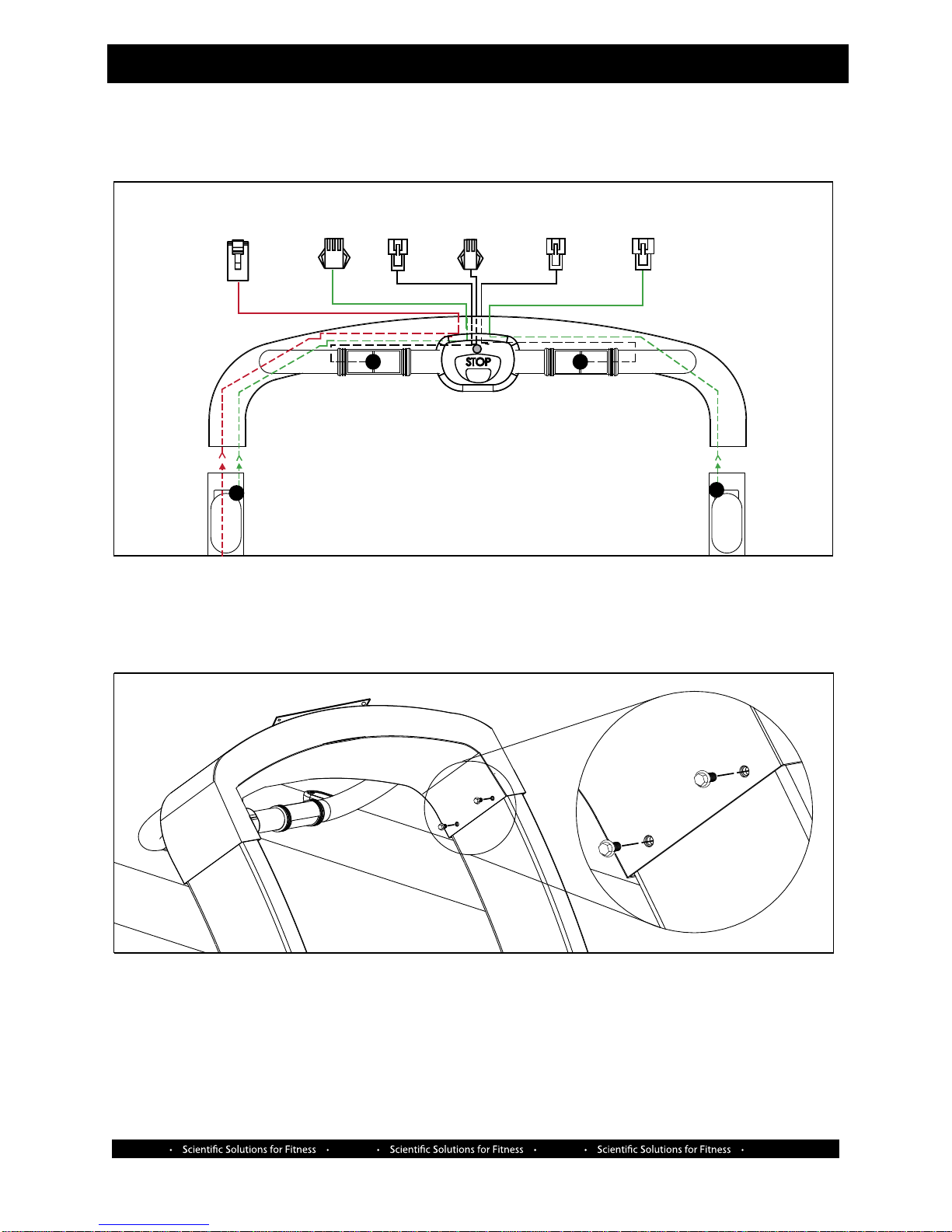
STEP 1- Connect the cables from the center weldment to the back of the console.
NOTE: Use the above chart for cable connection designation.
STEP 2- Carefully push the connected cables back into the opening of the center weldment and align the
console mounting holes with the holes of the weldment mounting plate
STEP 3- Using a phillips screw driver secure the console the the center weldment with (Qty. 4)
M5 x 12mm screws. NOTE: A ring lug extension from the emergency tether will need to be secured under one
of the screws as shown above.
3. Install Console To Center Weldment
Rear view of console
connection board
P11
P10
P9
P4P3
P6
2-pin
female
2
3-pin
female 2-pin
male
3
3-pin
male
2-pin
male
RJ45
4
5
6
SCIFIT SCIFIT SCIFIT SCIFIT
Assembly 3.6
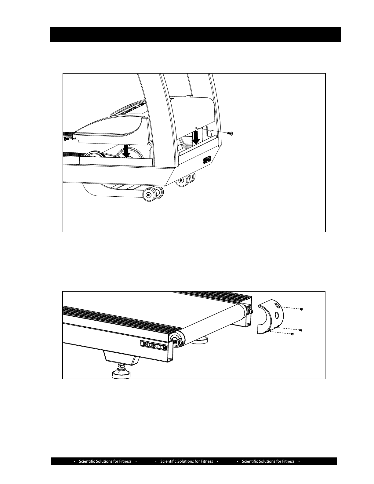
4. Install Motor Cover
STEP 1 - Place the motor cover onto the motor area and secure with the three supplied cover screws
(one screw not shown).
5. End Caps
STEP 1 - Beginning on the right side use a Phillips screw driver to attach the right end cap with
three M5 x 12mm screws
STEP 2 - Repeat step 1 for the left end cap.

SCIFIT SCIFIT SCIFITSCIFIT
Assembly 3.7
7. Connect Power Cord
STEP 1 - Verify the On/O switch is in the “OFF” position located at the front of the machine, then
attach the supplied power cord and plug the other end into the wall socket.
On/O switch location
CautionCaution
Clockwise turn
raises frame
Counterclockwise turn
lowers the frame
Lock Nut
Counter
clockwise
6. Adjust Level Pads
STEP 1 - Turn the level pad Height adjustment nut clockwise (raises frame) or counterclockwise
(lowers frame) on both right and left side until the acceptable height is achieved .
REQUIRED TOOLS: Leveler and Cresent wrench that will open up to 32mm.
STEP 2 - When the machine is level, secure the Lock nut up against the Adjustment nut so it can’t
move.
Height adjustment Nut
An unlevel machine may cause the Walkbelt not to be properly centered.
Clockwise
SCIFIT SCIFIT SCIFITSCIFIT
Assembly 3.8
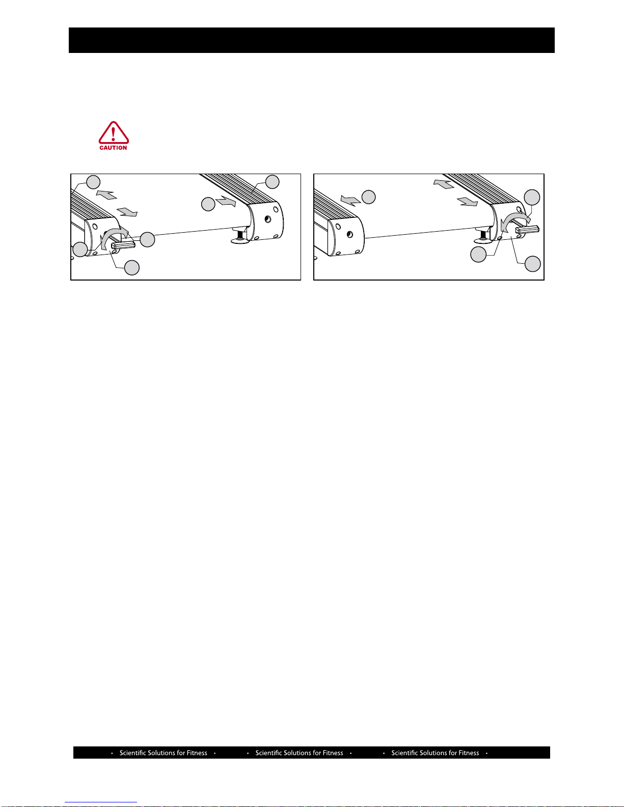
STEP 6 - Watch the tracking of the belt:
* If the belt tracks to the right, place the wrench in the right end cap (C) and turn clockwise (E)
a 1/4 turn at a time to make the belt move to the left (F).
* If the belt tracks to the left, place the wrench in the left end cap (B) and turn clockwise (E)
a 1/4 turn at a time to make the belt move right (G).
STEP 7 - When the belt is tracking in the center consistantly, than increase the speed to 5 mph and
adjust the belt according to the process in step 6.
STEP 8 - Stop the machine and proceed to the “Belt Tension Test”
Belt Tension Test
STEP 1 - With the machine in the idle mode, place you feet on the siderails of the frame to stradle the
belt.
STEP 2 - Press the “Quick Start” key and increase the speed to 2 mph.
STEP 3 - Grab hold of both left and right handrails, then begin to walk on the belt.
STEP 4 - Stomp one foot in front of the other just in front of the motor cover to try to make the belt
stop.
*If the belt slips, then more tension is needed and step 6 will need to be repeated.
*If the belt does not slip, then no further tensioning is required.
STEP 5 - Reattach the side rails previously removed.
CautionCaution
8. Belt Alignment
STEP 1 - Remove the left and right siderails (A)
STEP 2 - Located in the left (B) and right (C) end caps, use the supplied 5/16 (8mm) T-handle wrench
to turn the belt adjustment bolt (D) counter clockwise to loosen the belt.
STEP 3 - Center the walk belt manually within the walk deck.
STEP 4 - Turn the belt adjustment bolt clockwise (E) equally for both endcaps until the belt is tuant.
STEP 5 - Press the “Quick Start” key and set the speed to 2 mph.
An unlevel machine may cause the Walkbelt not to be properly centered.
B
GF
A
A
C
D
E
D
E
CC turns loosens
C turns tighten
CC turns loosens
C turns tighten

SCIFIT SCIFIT SCIFIT SCIFIT
Placement
Installation and Maintenance 4.1
Aviod placing the treadmill in direct sunlight, in areas of extreme
temperature or humidity or where the equipment may be splashed
with any uid. This treadmill is intended for indoor use only. Position
the treadmill so the plug is easily accessible.
Allow a minimum of 20” (508mm) between the wall and other
treadmills when in use.
Allow a safety area of 79” (2000mm) x 36” (914mm) square
behind the treadmill when in use.
Moving
The treadmill has wheels at the front of the machine attached to
the incline weldment assembly for easy handling.
These built-in wheels are designed for short distance relocation of
the treadmill, not for moving or delivery.
To move a short distance, incline the machine to 10%, then uplug
from the wall outlet, lift the rear of the treadmill and move.
CAUTION:
*When moving the machine it is strongly recommended that two
people be used.
*Please use furniture dollys to move the treadmill longer distances.
Treadmill Maintenance Schedule
Any mechanical or electrical work conducted
within the main body of a medical CE class IIa
unit MUST be recalibrated. The generic
maintenance schedule below should be applied
to medical CE and non-medical CE products
After intense training, always clean your SCIFIT product. Perspiration that stays in contact with the frame, casing, and
console may cause rust or other damage. Clean surfaces with water and mild soap, then dry with a towel.
Follow the schedule below to maintain optimal performance of a SCIFIT treadmill
Frame, Motor Cover, Damp Cloth Daily Club Maintenance
Console
LCD Screen LCD TV Screen Weekly Club Maintenance
soft cleaning cloth
Inside Motor Cover Vacuum Monthly Club Maintenance
Inspect Drive Belt Tension Gauge Monthly Club Maintenance
80-90 ftlbs
(119 - 134 Kg/m)
COMPONENT USE WHEN BY WHOM
Inspect Walkbelt Belt Tension Test Monthly Club Maintenance
(Assembly. section 3.8)
Replace if damaged
Inspect Walk Deck Flip once a year Yearly Club Maintenance
Replace if Damaged As Needed
Front/Rear Rollers Damp cloth As Needed Club Maintenance
Replace if Damaged
Actuator Elevation General purpose Annually Club Maintenance
Screw Shaft grease

SCIFIT SCIFIT SCIFIT SCIFIT
4.2
Installation and Maintenance
UNITED STATES CUSTOMER SERVI CE
For assistance in the service of SCIFIT products;
phone : (800) 745-1373 or (918) 359-2040
fax : (918) 359-2045
e-mail: service@scifit.com
The Product Support department is staffed from 7:00
AM to 6:00 PM CST Monday through Friday.A voice
mail service is available 24 hours a day for recording
messages to request technical support and to order
replacement parts.Our mailing address is:
SCIFIT Systems Inc.
5151 S.110th E.Ave.
Tulsa, OK 74146
USA
UK & EUROPEAN CUSTOMER SERVICE
phone : +44 1344 300022
fax: +44 1344 868838
e-mail: info@scifit.uk.com
SCIFIT LTD (UK)
Lexham House
Forest Road
Binfield
Berkshire, RG42 4HP
UK
Company Number: 5970624 (UK)
* COUNTRIES OUTSIDE OF UK & EUROPE
PLEASE USE USA CONTACT NUMBERS*
Order online 24/7at www.SCIFIT.com
Other manuals for AC5000 series
3
This manual suits for next models
3
Table of contents
Other SCIFIT Treadmill manuals


Popular Treadmill manuals by other brands


Pro-Form
Pro-Form 725 proform Model No. 831.297780 user manual

FREE MOTION
FREE MOTION Incline trainer user manual

SereneLife
SereneLife SLFTRD45 user manual

Life Span
Life Span TR1200i owner's manual

BH Hipower
BH Hipower SK Series Instructions for assembly and use

Pro-Form
Pro-Form 1195 Zlt Cwl Treadmill Gebruiksaanwijzing