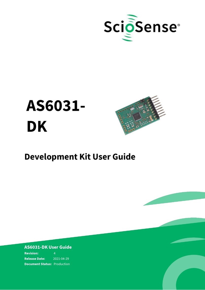
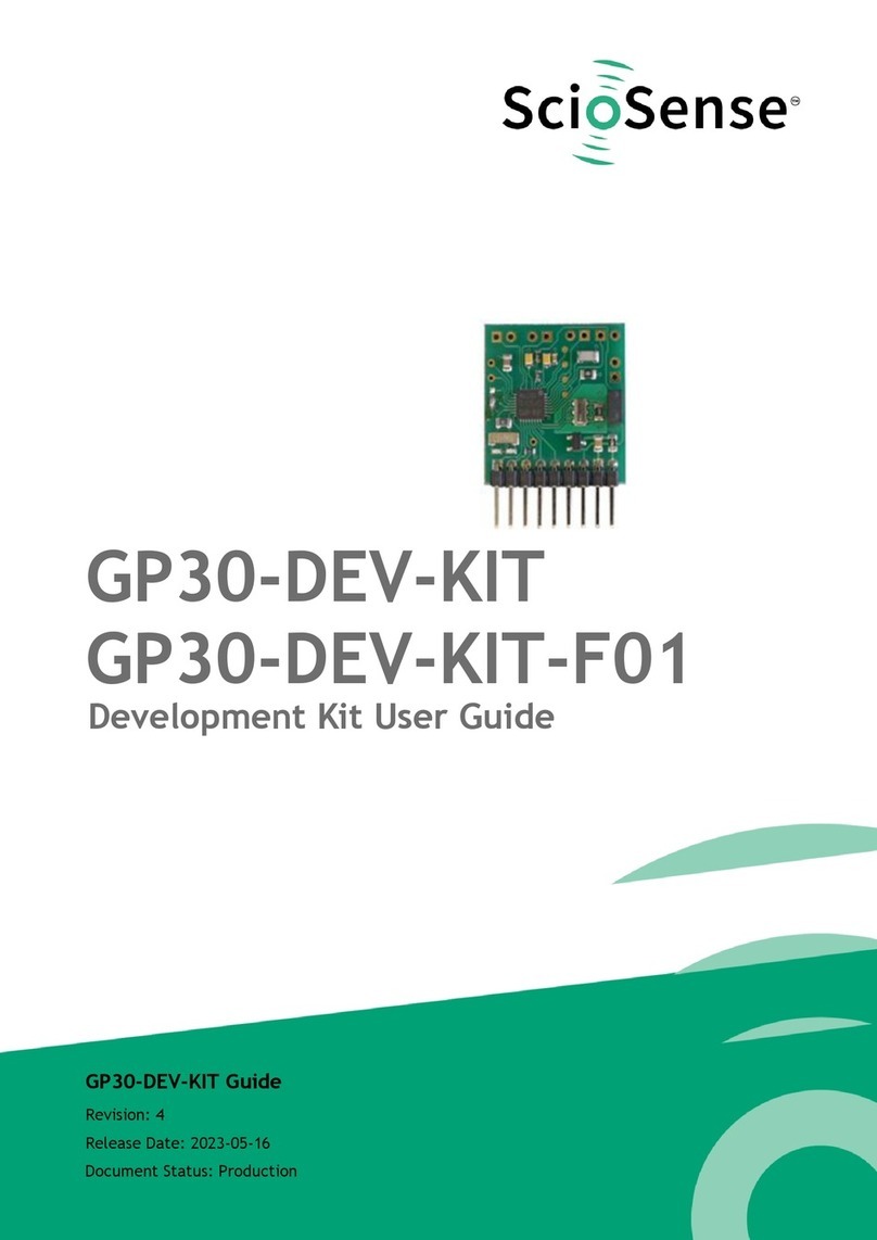
ScioSense AS6040-QF DK User manual

Development Kit User Guide
AS6040-QF_DK
AS6040-QF_DK User Guide
Revision: 4
Release Date: 2021-10-22
Document Status: Production

2
AS6040-DK User Guide SC-000865-UG 4 / 2021-10-22 / Production
CONTENTS PAGE
Content Guide
Content Guide .................................................................................................... 2
1Introduction ................................................................................................. 3
1.1 Ordering Codes .........................................................................................3
2Quick Start Guide .......................................................................................... 4
3Hardware Description ..................................................................................... 5
3.1 Introduction .............................................................................................5
3.2 Series Load Resistors...................................................................................5
3.3 Filter for PGA ...........................................................................................6
3.4 Communication Interface .............................................................................6
4Measurements in Practice ................................................................................ 7
5Schematics, Layers & BOM ............................................................................... 8
6Transducers ................................................................................................ 11
7RoHS Compliance & ScioSense Green Statement.................................................... 14
8Copyrights & Disclaimer.................................................................................. 14
9Revision information ..................................................................................... 15

AS6040-DK User Guide SC-000865-UG-4 / 2021-10-22 / Production
3
CONTENTS PAGE
1Introduction
The AS6040-DK development kit allows customers a quick and intuitive approach to using the AS6040
UFC in ultrasonic flow meter applications.
The kit includes of four elements:
AS6040-QF_DK_RB reference board V2.0, based on
AS6040-BQFM in QFN48 package
Cable to connect the PICOPROG USB-to-SPI interface
with the reference board
PICOPROG V3.0 programmer
USB cable to connect the PICOPROG with a PC
Figure 1: Functional Blocks
Please download the software for the kit from https://downloads.sciosense.com/AS6040 and look
for the latest revision of UfcEvaluationSoftware….zip
1.1 Ordering Codes
Table 1: Pin description
Ordering code
Part Number
Description
AS6040-QF_DK V1.0
221010003
AS6040 Demo kit including PICOPROG and cables
AS6040-QF_DK_RB V2.0
221010003
AS6040 reference board

4
AS6040-DK User Guide SC-000865-UG-4 / 2021-10-22 / Production
CONTENTS PAGE
2Quick Start Guide
This section describes how to quickly set up the AS6040 development kit, to establish basic operation
and to make first measurements.
It is crucial to install the software before connecting the evaluation kit to your computer. The
software can be downloaded here:
https://downloads.sciosense.com/AS6040
•Unzip the package to the desired directory, open directly “UfcEvaluationSoftware.exe” and
follow the instructions on the screen.
•Connect the PICOPROG V3.0 to the computer when requested, using the USB cable. And connect
the board to the PICOPROG using the DB15 connector cable.
•Connect your spool piece to US_UP and US_DOWN. US_UP fires upstream, means versus flow.
US_DOWN fires downstream, with the flow.
The following screen will appear:
Figure 2: Opening page
•Verify that the right device is selected.
•Select one of the available projects or configuration files, press “Load Project” or “Load Config”
and then on the left press “Write Config”.
•Press “Start Measurement” to begin measuring.

AS6040-DK User Guide SC-000865-UG-4 / 2021-10-22 / Production
5
CONTENTS PAGE
3Hardware Description
3.1 Introduction
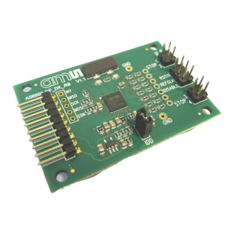
The AS6040-QF_DK_RB board, shown in figure 3, is a front-end mainly for gas meters but also water
meters. The transducers and temperature sensors are directly connected to this board. It comes with
a 32.768 kHz quartz (X2) and a 8 MHz ceramic oscillator (X1).
TP5 – RECEIVE_SIG
TP7 – GPIO5
TP8 – LPMODE
J4 – COMP_IN
Transducers:
—— US_DOWN
—— GND
—— GND
—— US_UP
Icc
—— GND
—— TPI_GND2
—— TPI_GND1
—— TPI_M2_A
—— TPI_M2_B
—— TPI_M1_A
—— TPI_M1_B
TP3 – GPIO0
TP2 – GPIO1
TP1 – GPIO2
TP10 – GPIO3
TP11 –
GPIO4
INTN ——
MISO ——
SCK ——
MOSI ——
SSN ——
- ——
VCC_LEVEL ——
GND ——
VCC ——
J6 – US_VREF
Figure 3: AS6040-QF_DK_RB
3.2 Series Load Resistors
The series load resistors, sometimes also called matching resistors, are assembled by default with
680 Ohm. In case the impedance of the transducers differs a lot those can be replaced.
Load resistor FIRE_DOWN
Load resistor FIRE_UP
Figure 4: Series load or matching resistors

6
AS6040-DK User Guide SC-000865-UG-4 / 2021-10-22 / Production
CONTENTS PAGE
In application for water with typical frequencies of 1 or 2 MHz the series resistors might better be
lower, like 330 Ohm. From experience, the matching does not need to be precise but a rough fit.
3.3 Filter for PGA
In applications with high gain (> 20V/V, like in gas meters) the PGA noise may be reduced by an
external filter. The filter is configured by setting TI_PGA_CON_MODE = 2 in the evaluation software.
This controls the internal switch to the pad INVERT_IN. The filter has to be connected between the
INVERT_IN and COMP_IN pins.
The choices for the external resistors and capacitor depend on the fire frequency for the ultrasonic
transducer. For gas meters we recommend the following recommended values:
Ri= 5.6 kΩ (R13), C = 10 nF (C31), Ro= 2.2 kΩ (R20)
R20 = C31 R13 =
Ro = 2.2 kΩ 10 nF Ri = 5.6 kΩ
Figure 5: AS6040-QF_DK_RB
The T-filter only becomes effective with high amplification. It then reduces the gain and noise of
the PGA at low frequencies. From PGA_TRIM >= 7 on the filter reduces the standard deviation of TOF
values. But it also overrides the auto-zero function, and therefore the auto-zero should be disabled
when a filter is used, TI_PGA_AZ_DIS = 1.
3.4 Communication Interface
The PICOPROG device is a USB-to-SPI converter box that interfaces all UFC evaluation systems. The
PICOPROG is registered by the operating system initially as “PICOPROG v2.0 unprogrammed” (for
both PICOPROG V2.0 and V3.0). As soon as the UFC evaluation software starts, a special firmware is
written into the PICOPROG to handle the SPI communication with the AS6040-QF_DK_RB board. The
PICOPROG is now listed as “UNIPRO” in the device manager.
The flat connector connecting the PICOPROG and the AS6040-QF_DK_RB includes the power lines and
the SPI communication lines. VCC_LEVEL is the voltage feedback for the PICOPROG level shifters.

AS6040-DK User Guide SC-000865-UG-4 / 2021-10-22 / Production
7
CONTENTS PAGE
4Measurements in Practice
We propose to start with one of the example configurations. The most important parameters to
review and set are:
•Fire pulse frequency (typically 100kHz, 200kHz or 500kHz)
•Number of fire pulses (20 is a good start)
•Number of TOF hits (10 is a good start)
•Noise mask Window should be =1. Then directly after the fire burst, with about 10µs delay, the
chip switches to receive. Typically you see a short oscillation due to the switching between the
send and receive transducer.
•Charge pump voltage and PGA gain of receiving amplitude (to get a receive amplitude of 200 to
400mV)
In general, we recommend to have a look at the receive signal by means of an oscilloscope. This
clearly helps to find the right settings.
If the signal is measured at the PGA output, at test pin J4 (pin 17, COMP_IN) then there is no influence
of the probe to the measured time values. In Figure 3 this point is marked. Another probe should be
connected to US_UP for the trigger signal. When looking at minimum noise then this probe of course
needs to be removed.
Figure 6: Typical send and receive signals
When working with real gas there might be the need for an external amplification with higher gain
than offered by the internal PGA. In this case, please refer to application note SC-000942-AN,
“AS6040 with external amplifier” for details.
NOISE_MASK
TOF_MH_RLS_DLY_x
Starthit

AS6040-DK User Guide SC-000865-UG-4 / 2021-10-22 / Production
9
CONTENTS PAGE
Figure 8: AS6040-QF_DK_RB layout 2:1t
Figure 9: AS6040-QF_DK_RB assembly 2:1
Table 2: Bill of materials for AS6040-QF_DK_RB V2.0
Quantity
Designator
Value
Comment
Footprint
3
C1, C10, C11
10p
CHIP-CAPACITOR 0603
0603
1
C18
22p
CHIP-CAPACITOR 0603
0603
1
C31
10n
CHIP-CAPACITOR 0603
0603
5
C4, C5, C9, C25, C28
100n
CHIP-CAPACITOR 0603
0603

10
AS6040-DK User Guide SC-000865-UG-4 / 2021-10-22 / Production
CONTENTS PAGE
1
C6
680n
CHIP-CAPACITOR 0603
0603
1
C3
100n/25V
CHIP-CAPACITOR 0603
0603
2
C12, C32
100u/6V3
CHIP-CAPACITOR 0805
0603
1
C29
100n C0G
CHIP-CAPACITOR GRM31C5C1E104JA01L
1206
3
C7, C19, C22
2u2/16V
CHIP-CAPACITOR 603
0603
1
C8
22u/20V
Tantal BF. B TAJB226K020RNJ AVX
7
C2, C13, C14, C15,
C16, C17, C20
CHIP-CAPACITOR 0603
0603
3
R1, R2, R3
4R7
CHIP-RESISTOR 0603
0603
1
R20
2k2
CHIP-RESISTOR 0603
0603
1
R13
5k6
CHIP-RESISTOR 0603
0603
1
R10
560k
CHIP-RESISTOR 0603
0603
1
R8
10M
CHIP-RESISTOR 0603
0603
2
R9, R12
680R
CHIP-RESISTOR 0805
0805
1
R16
1K
CHIP-RESISTOR 0805 RN73C2A1K0B
4
R4, R11, R14, R19
CHIP-RESISTOR 0603
0603
3
R5, R6, R15, R18
CHIP-RESISTOR 0805
0805
1
U1
AS6040-BQF
QFN48
2
U3, U4
LMP7711
1
U2
3,0V
XC6206P302MR-G Torex
1
X1
8Mhz
CERAMIC RESONATOR CSTNE8M00G550000R0
1
X2
32,768kHz
Quartz Crystal KX-327XS
1
J1
Male Connector 7x1x180° 2,54
1
J2
Male Connector 2x1x180° 2,54
1
J4
Male Connector 2x1x90° 2,54

AS6040-DK User Guide SC-000865-UG-4 / 2021-10-22 / Production
11
CONTENTS PAGE
6Transducers
For transducers we can recommend products from Zhejiang Jiakang Electronics Co., Ltd.:
Table 3: Ordering information
Sensor
Raw Value
Range
Gas meters
PSC500K018060H2AD2-B1
f: 500 ± 10 kHz
Cp 470 pF ± 10%
Top -35 to 70 °C
PSC200K018102H3AD0-B
f: 200 ± 10 kHz
Cp 2000 pF ± 20%
Top -35 to 70 °C
PSC200K018102H3AD1-B1
f: 200 ± 10 kHz
Cp 430 pF ± 20%
Top -35 to 70 °C
Angle 12° (average)
Q 2.9 ± 0.3 g
PSC200K016191H2AD1-B1
f: 200 ± 10 kHz
Cp 600 pF ± 20%
Top -35 to 70 °C
Angle > 6° (half angle)
Water meters
PSC1.0M020100H2AD0-
B0/PSC1.0M020107H2AD0-
B0
f: 1.0 ± 0.1 MHz
R1MHz 100 to 350 Ω
Cp 1300 pF ± 20%
Top -40 to 85 °C
S >800mV
(@ 2Vpp, 110mm)
φ20.6±0.2 10.2±0.2
φ16.8±0.2
7.6±0.2

12
AS6040-DK User Guide SC-000865-UG-4 / 2021-10-22 / Production
CONTENTS PAGE
PSC1.0M019168H2AD2-B0
f: 1.0 ± 0.1 MHz
R1MHz 150 to 400 Ω
Cp 1000 pF ± 20%
Top -40 to 85 °C
S >700mV
(@ 2Vpp, 110mm)
PEEK
PSC1.0M020160H2AD1-B0
f: 1.0 ± 0.1 MHz
R1MHz 150 to 350 Ω
Cp 1200 pF ± 20%
Top -40 to 85 °C
S >800mV
(@ 2Vpp, 110mm)
塑料外壳
PSC1.0M014083H2AD2-B0
f: 1.0 ± 0.1 MHz
R1MHz 500 to 1500 Ω
Cp 600 pF ± 20%
Top -40 to 85 °C
S >450mV
(@ 2Vpp, 110mm)
塑料外壳
PSC1.0M022300H2AD4-B0
f: 1.0 ± 0.1 MHz
R1MHz 150 to 500 Ω
Cp 1300 pF ± 20%
Top -40 to 85 °C
S >700mV
(@ 2Vpp, 110mm)
PSC2.0M014083H2AD2-B0
f: 2.0 ± 0.1 MHz
R2MHz 100 to 400 Ω
Cp 1200 pF ± 20%
Top -40 to 85 °C
S >450mV
(@ 2Vpp, 110mm)
PSC2.0M018223H2AD2-B0
f: 2.0 ± 0.1 MHz
R2MHz 150 to 500 Ω
Cp 1100 pF ± 20%
Top -40 to 85 °C
S >200mV
(@ 3Vpp, 140mm)
PSC4.0M018223H2AD2-B0
f: 4.0 ± 0.2 MHz
R2MHz 30 to 150 Ω
Cp 2050 pF ± 20%
Top -40 to 85 °C
S >200mV
(@ 3Vpp, 140mm)
Tstrg = -40° to 85°C for all parts

14
AS6040-DK User Guide SC-000865-UG-4 / 2021-10-22 / Production
CONTENTS PAGE
7RoHS Compliance & ScioSense Green Statement
RoHS: The term RoHS compliant means that Sciosense B.V. products fully comply with current RoHS
directives. Our semiconductor products do not contain any chemicals for all 6 substance categories,
including the requirement that lead does not exceed 0.1% by weight in homogeneous materials.
Where designed to be soldered at high temperatures, RoHS compliant products are suitable for use
in specified lead-free processes.
ScioSense Green (RoHS compliant and no Sb/Br): ScioSense Green defines that in addition to RoHS
compliance, our products are free of Bromine (Br) and Antimony (Sb) based flame retardants (Br or
Sb do not exceed 0.1% by weight in homogeneous material).
Important Information: The information provided in this statement represents Sciosense B.V.
knowledge and belief as of the date that it is provided. Sciosense B.V. bases its knowledge and belief
on information provided by third parties, and makes no representation or warranty as to the accuracy
of such information. Efforts are underway to better integrate information from third parties.
Sciosense B.V. has taken and continues to take reasonable steps to provide representative and
accurate information but may not have conducted destructive testing or chemical analysis on
incoming materials and chemicals. Sciosense B.V. and Sciosense B.V. suppliers consider certain
information to be proprietary, and thus CAS numbers and other limited information may not be
available for release.
8Copyrights & Disclaimer
Copyright Sciosense B.V High Tech Campus 10, 5656 AE Eindhoven, The Netherlands. Trademarks
Registered. All rights reserved. The material herein may not be reproduced, adapted, merged,
translated, stored, or used without the prior written consent of the copyright owner.
Devices sold by Sciosense B.V. are covered by the warranty and patent indemnification provisions
appearing in its General Terms of Trade. Sciosense B.V. makes no warranty, express, statutory,
implied, or by description regarding the information set forth herein. Sciosense B.V. reserves the
right to change specifications and prices at any time and without notice. Therefore, prior to designing
this product into a system, it is necessary to check with Sciosense B.V. for current information. This
product is intended for use in commercial applications. Applications requiring extended temperature
range, unusual environmental requirements, or high reliability applications, such as military, medical
life-support or life-sustaining equipment are specifically not recommended without additional
processing by Sciosense B.V. for each application. This product is provided by Sciosense B.V. “AS IS”
and any express or implied warranties, including, but not limited to the implied warranties of
merchantability and fitness for a particular purpose are disclaimed.
Sciosense B.V. shall not be liable to recipient or any third party for any damages, including but not
limited to personal injury, property damage, loss of profits, loss of use, interruption of business or
indirect, special, incidental or consequential damages, of any kind, in connection with or arising out
of the furnishing, performance or use of the technical data herein. No obligation or liability to
recipient or any third party shall arise or flow out of Sciosense B.V. rendering of technical or other
services.

AS6040-DK User Guide SC-000865-UG-4 / 2021-10-22 / Production
15
CONTENTS PAGE
9Revision information
Table 4: Revision history
Revision
Date
Comment
Page
1.0
2019
Initial version, preliminary
All
2.0
2020 Jun 06
Release
All
3.0
2021 Apr 20
Part description corrected, reference to new UfcEvaluation Software
All
4.0
2021 Oct 22
Reference to update schematics and layout of reference board.
PICOPROG picture. Transfer into new ScioSense layout
All
Note(s) and/or Footnote(s):
1. Page and figure numbers for the previous version may differ from page and figure numbers in
the current revision.
2. Correction of typographical errors is not explicitly mentioned.

ScioSense is a Joint Venture of ams AG
Address: Sciosense B.V.
High Tech Campus 10
5656 AE Eindhoven
The Netherlands
Contact: www.sciosense.com
info@sciosense.com
This manual suits for next models
3
Table of contents
Other ScioSense Microcontroller manuals
Popular Microcontroller manuals by other brands

Nuvoton
Nuvoton NuMicro NuTiny-SDK-NUC029KGE user manual

Cypress
Cypress PSOC CY8CKIT-146 quick start guide

Motorola
Motorola AT Commands G24-L technical information

Silicon Laboratories
Silicon Laboratories C8051F41 Series user guide

Altera
Altera DE5-NET user manual

Dialog Semiconductor
Dialog Semiconductor DA1458 Series user manual

NXP Semiconductors
NXP Semiconductors Freescale Semiconductor MPC8308 Errata sheet

Fujitsu
Fujitsu MB86R01 Application note

InterNiche Technologies
InterNiche Technologies PIC32MX user guide

Intel
Intel Euclid Getting started guide

Dialog
Dialog DA1468 Series user manual

Nuvoton
Nuvoton NuMicro M483 Series user manual