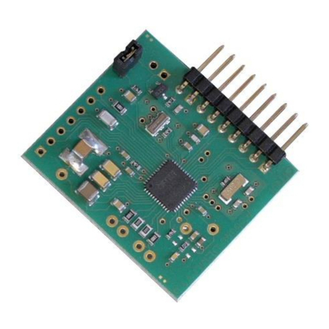
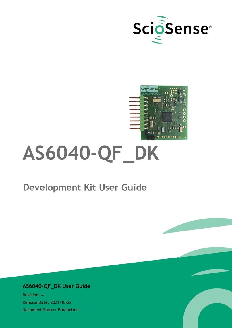
ScioSense AS6500-QF DK User manual

Development Kit User Guide
AS6500-QF_DK
AS6500-QF_DK User Guide
Revision: 2
Release Date: 2021-10-22
Document Status: Production

2
AS6500-DK User Guide SC-001504-UG 2 / 2021-10-22 / Production
CONTENTS PAGE
Content Guide
Content Guide .................................................................................................... 2
1Introduction ................................................................................................. 3
1.1 Ordering Codes .........................................................................................3
2Quick Start Guide .......................................................................................... 4
2.1 Install the Software ....................................................................................4
2.2 Install the Hardware: ..................................................................................4
2.3 Start Software ..........................................................................................5
3Hardware Description ..................................................................................... 5
4Software Description ...................................................................................... 6
4.1 Main Window ............................................................................................6
4.1.1 Stop Page ...........................................................................................6
4.1.2 REFCLK/SPI Page...................................................................................7
4.2 Menu & Support Windows .............................................................................7
4.2.1 File...................................................................................................7
4.2.2 Tools.................................................................................................8
5Schematics, Layers & BOM .............................................................................. 10
6RoHS Compliance & ScioSense Green Statement.................................................... 13
7Copyrights & Disclaimer.................................................................................. 13
8Revision information ..................................................................................... 14

AS6500-DK User Guide SC-001504-UG-2 / 2021-10-22 / Production
3
CONTENTS PAGE
1Introduction
The AS6500-DK development kit allows customers a quick and intuitive approach to using the AS6500
TDC applications.
The kit includes of four elements:
AS6500-QF_DK_RB reference board V2.0, based on
AS6500-BQFM in QFN48 package
Cable to connect the PICOPROG USB-to-SPI interface
with the reference board
PICOPROG V3.0 interface
USB cable to connect the PICOPROG with a PC
Figure 1: Functional Blocks
Please download the latest software for the kit from
https://www.downloads.sciosense.com/AS6500
1.1 Ordering Codes
Table 1: Pin description
Ordering code
Part Number
Description
AS6500-QF_DK V1.0
221050003
AS6500 Demo kit including PICOPROG and cables
AS6500-QF_DK_RB V2.0
221050003
AS6500 reference board

4
AS6500-DK User Guide SC-001504-UG-2 / 2021-10-22 / Production
CONTENTS PAGE
2Quick Start Guide
This section describes how to set up the GPX2-EVA-KIT, establish basic operation and make
measurements quickly.
2.1 Install the Software
Please download the latest software for the kit from:
Link: https://downloads.sciosense.com/as6500
It is crucial to install the software before connecting the evaluation kit to your computer. A default
driver loading of your OS may interfere with correct installation.
Table 2: Software installation
Step
Screen
Download the latest software installation
package to the desired directory.
Unzip the package to the desired directory.
Open “setup.exe” from the unzipped directory.
Follow the instructions on the screen. The the
software will be available from the Program
Files folder or the Start menu.
When connecting the PicoProg to the USB port
it will be listed first as “picoprog v2.0 un-
programmed” device. This is true also for
PicoProg V3.0.
In the drivers folder you find the driver for a
manual installation.
Starting the software will download a special
firmware into the PICOPROG,
picoprog_gpx2_v005.hex or higher, and the
device will now be listed as “UNIPRO”:
2.2 Install the Hardware:
•Make sure software is installed correctly before proceeding with this step!
•Connect your computer with the PicoProg V3.0 using USB cable.
•Connect PicoProg V3.0 and the evaluation board DB15 cable or directly. The board is supplied via
the USB.
•The green LED on the evaluation kit should be on.
•Connect your signal source.

AS6500-DK User Guide SC-001504-UG-2 / 2021-10-22 / Production
5
CONTENTS PAGE
2.3 Start Software
•Execute the AS6500 front panel Software. The communication status should be green
•The software starts with an initial configuration, that can be opened the default configuration
file config_default.cfg.
•Press “Power On Reset! – “Write Config” – “Init Reset”
•Press “Start Measurement”
The measurement should run and results should be displayed now.
3Hardware Description
The AS6500-QF_DK_RB board, shown in Figure 2, is a basic board for the 4-channel time-to-digital
converter AS6500. The reference clock can be applied from external via pin or from the on-board
5 MHz quartz oscillator (X1).
INTN ——
MISO ——
SCK ——
MOSI ——
SSN ——
- ——
VCC_LEVEL ——
GND ——
VCC ——
Icc
Signal source:
—— STOP1
—— STOP2
—— REFCLK
—— STOP3
—— STOP4
Figure 2: Reference board
The board is connected to the PC via the PICOPROG, a USB-to-SPI converter. The PICOPROG is
registered by the operating system initially as “PICOPROG v2.0 unprogrammed”. As soon as the
AS6500-QF_DK_RB evaluation software starts, a special firmware is written into the PICOPROG to
handle the SPI communication with the AS6500-DK. The PICOPROG is now listed as “UNIPRO” in the
device manager. For SPI communication only, PICOPROG version 2.0 is sufficient.
The flat connector connecting the PICOPROG and the AS6500-QF_DK_RB. includes the power lines
and the SPI communication lines. VCC_LEVEL is the voltage feedback for the PICOPROG level shifters.

6
AS6500-DK User Guide SC-001504-UG-2 / 2021-10-22 / Production
CONTENTS PAGE
4Software Description
This section describes how to quickly set up theAS6500-DK, establish basic operation and make
measurements.
4.1 Main Window
The main windows shows two pages, one for configuration and one for results display:
4.1.1 Stop Page
On this window major settings are made:
•1. Selects the input pins that are used in the application
•2. Enable the internal measurement channels. Each pin refers to minimum one internal channel.
Two will be needed in case of channel combination.
•3. Select the resolution. High resolution achieves a betters single-shot rms noise, but at the cost
of pulse-pair resolution.
•4. Selects optional channel combination
•This can be for better pulse-pair resolution or for pulse width measurement. Both options demand
internally two channels per stop pin.
•5. Having done the settings, download the configuration and initialize the chip.
•6. Start the measurement.
•7. At the bottom the results for the four stop channels are displayed.
•8. In many cases the differences between the channels are of interest. This can be activated
here.
1
345
26
7
8
Figure 3: Stop page

AS6500-DK User Guide SC-001504-UG-2 / 2021-10-22 / Production
7
CONTENTS PAGE
4.1.2 REFCLK/SPI Page
PageAt this point, after successful completion of the above steps, a basic operation of the kit should
be possible.
Parameter REFCLK_DIVISIONS has to be set so that the frequency calculated is the same of the
reference clock used (5 MHz for the on-board reference). Then the output data will come with 1 LSB
= 1ps.
1
2
3
Figure 4: Setup page
4.2 Menu & Support Windows
Beside main window, the software menu allows the opening of other windows. There are some menu
items which are redundant to available buttons of main window.
4.2.1 File
•Load Config
This dialog box allows the path selection of a configuration file, covering the register settings,
necessary for a proper configuration of the AS6500. After opening this file, the control settings
are updated in the GUI.
•Save Config
This menu item allows the saving of the current GUI control settings into a configuration file
•Save Graph Data
Allows to store the measurement data as they are stored in the data buffer for the graphical

8
AS6500-DK User Guide SC-001504-UG-2 / 2021-10-22 / Production
CONTENTS PAGE
display. It is possible to store the STOP data only or the STOP together with the reference
numbers.
Figure 5: Menu
•Close
Close all open windows of the AS6500-QF_DK Evaluation software.
4.2.2 Tools
•Run Measurement
Same function as “Start/Stop Measurement” button in “Measurement” tab of main window.
•Graph
Opens the window for a graphical display of the measurement data
Figure 6: Menu
•Registers
Opens a separate window for the display and setting of the configuration registers and the display
of the read registers.

AS6500-DK User Guide SC-001504-UG-2 / 2021-10-22 / Production
11
CONTENTS PAGE
Figure 10: AS6500-QF_DK_RB layout
Figure 11: AS6500-QF_DK_RB assembly
Table 3: Bill of materials for AS6500-QF_DK_RB
Quantity
Designator
Value
Comment
Footprint
1
U1
AS6500
QFN40
1
U6
3.0 V
ADP163AUJZ Analog Devices
1
X1
5 MHz
KX-20 Quartzs Geyer
3
C8, C10, C12
100 nF
Chip capacitor
0805
2
C34,C35
15 pF
Chip capacitor
0805
5
C2,C4,C7,C9,C11
22 µF
Chip capacitor
0805
2
R19,R110
0 Ω
Chip capacitor
0805

12
AS6500-DK User Guide SC-001504-UG-2 / 2021-10-22 / Production
CONTENTS PAGE
2
R10,R51
100 Ω
Chip resistor
0805
7
R22,R23,R24,R25,R26,
R27,R28
100 kΩ
Chip resistor
0805
9
R1,R18,R20,R29,R30,
R31,R32,R33
1 MΩ
Chip resistor
0805
4
R21,R61,R64,R65
1.1 MΩ
Chip resistor
0805
1
R5
604 kΩ
Chip resistor
0805
1
R12
60.4 kΩ
Chip resistor
0805
1
R4
910 kΩ
Chip resistor
0805
1
R8
10 MΩ
Chip resistor
0805
1
J6
7 x 1 x 90°
Connector
2.54
1
J1
2 x 1 x 90°
Connector
2.54
1
J2
5 x 1 x 180°
Connector
2.54

AS6500-DK User Guide SC-001504-UG-2 / 2021-10-22 / Production
13
CONTENTS PAGE
6RoHS Compliance & ScioSense Green Statement
RoHS: The term RoHS compliant means that Sciosense B.V. products fully comply with current RoHS
directives. Our semiconductor products do not contain any chemicals for all 6 substance categories,
including the requirement that lead does not exceed 0.1% by weight in homogeneous materials.
Where designed to be soldered at high temperatures, RoHS compliant products are suitable for use
in specified lead-free processes.
ScioSense Green (RoHS compliant and no Sb/Br): ScioSense Green defines that in addition to RoHS
compliance, our products are free of Bromine (Br) and Antimony (Sb) based flame retardants (Br or
Sb do not exceed 0.1% by weight in homogeneous material).
Important Information: The information provided in this statement represents Sciosense B.V.
knowledge and belief as of the date that it is provided. Sciosense B.V. bases its knowledge and belief
on information provided by third parties, and makes no representation or warranty as to the accuracy
of such information. Efforts are underway to better integrate information from third parties.
Sciosense B.V. has taken and continues to take reasonable steps to provide representative and
accurate information but may not have conducted destructive testing or chemical analysis on
incoming materials and chemicals. Sciosense B.V. and Sciosense B.V. suppliers consider certain
information to be proprietary, and thus CAS numbers and other limited information may not be
available for release.
7Copyrights & Disclaimer
Copyright Sciosense B.V High Tech Campus 10, 5656 AE Eindhoven, The Netherlands. Trademarks
Registered. All rights reserved. The material herein may not be reproduced, adapted, merged,
translated, stored, or used without the prior written consent of the copyright owner.
Devices sold by Sciosense B.V. are covered by the warranty and patent indemnification provisions
appearing in its General Terms of Trade. Sciosense B.V. makes no warranty, express, statutory,
implied, or by description regarding the information set forth herein. Sciosense B.V. reserves the
right to change specifications and prices at any time and without notice. Therefore, prior to designing
this product into a system, it is necessary to check with Sciosense B.V. for current information. This
product is intended for use in commercial applications. Applications requiring extended temperature
range, unusual environmental requirements, or high reliability applications, such as military, medical
life-support or life-sustaining equipment are specifically not recommended without additional
processing by Sciosense B.V. for each application. This product is provided by Sciosense B.V. “AS IS”
and any express or implied warranties, including, but not limited to the implied warranties of
merchantability and fitness for a particular purpose are disclaimed.
Sciosense B.V. shall not be liable to recipient or any third party for any damages, including but not
limited to personal injury, property damage, loss of profits, loss of use, interruption of business or
indirect, special, incidental or consequential damages, of any kind, in connection with or arising out
of the furnishing, performance or use of the technical data herein. No obligation or liability to
recipient or any third party shall arise or flow out of Sciosense B.V. rendering of technical or other
services.

14
AS6500-DK User Guide SC-001504-UG-2 / 2021-10-22 / Production
CONTENTS PAGE
8Revision information
Table 4: Revision history
Revision
Date
Comment
Page
1
2019 Mar 14
Change of ownership from ams to ScioSense, status to release
All
2
2021 Oct 01
Updated pictures, new ScioSense layout
All
Note(s) and/or Footnote(s):
1. Page and figure numbers for the previous version may differ from page and figure numbers in
the current revision.
2. Correction of typographical errors is not explicitly mentioned.

Address: Sciosense B.V.
High Tech Campus 10
5656 AE Eindhoven
The Netherlands
Contact: www.sciosense.com
info@sciosense.com
This manual suits for next models
3
Table of contents
Other ScioSense Microcontroller manuals
Popular Microcontroller manuals by other brands

Texas Instruments
Texas Instruments TI-InnovatorHub Getting started guide

Freescale Semiconductor
Freescale Semiconductor MPC5553 Reference manual

Nerdonic
Nerdonic Exen Proto Setup guide

Cypress
Cypress S6E2CC Series manual

Silicon Laboratories
Silicon Laboratories SLSTK3701A user guide

Renesas
Renesas RX65N Series user manual

Nuvoton
Nuvoton NuMicro M23 Series user manual

DEUTSCHMANN AUTOMATION
DEUTSCHMANN AUTOMATION LOCON 200 instruction manual

Huawei
Huawei ViewPoint 8650C MCU quick start

Thinxtra
Thinxtra XKIT installation guide

Cypress
Cypress PSoC CY8CPROTO-062-4343W quick start guide

Texas Instruments
Texas Instruments CC2540DK-MINI user guide