ScioSense GP30-DEV-KIT User manual

Development Kit User Guide
GP30-DEV-KIT
GP30-DEV-KIT-F01
GP30-DEV-KIT Guide
Revision: 4
Release Date: 2023-05-16
Document Status: Production

2
GP30YD_DK SC-001776-UG 4 / 2023-05-16 / Production
CONTENTS PAGE
Content Guide
Content Guide .................................................................................................... 2
1Introduction ................................................................................................. 3
1.1 Ordering Codes .........................................................................................3
2Quick Start Guide .......................................................................................... 4
2.1 Install the Software ....................................................................................4
2.2 Install the Hardware ...................................................................................4
2.3 Quick Start for Initial Measurements ................................................................4
3Hardware Description ..................................................................................... 6
3.1 Introduction .............................................................................................6
3.2 Communication Interface .............................................................................6
4Software Description ...................................................................................... 7
4.1 Measurement............................................................................................7
4.1.1 First Step with Measurement Control Elements...............................................7
4.1.2 Time of Flight Measurement Results............................................................8
4.1.3 2-Wire Temperature Measurement Results ....................................................9
4.2 Ultrasonic Measurement Control ................................................................... 10
4.3 Temperature Measurement Control ............................................................... 11
4.4 General Control....................................................................................... 12
4.4.1 Firmware.......................................................................................... 12
4.5 Interfaces.............................................................................................. 13
4.5.1 Pulse Interface................................................................................... 13
4.5.2 UART............................................................................................... 13
4.6 Interrupt & Error Handling .......................................................................... 14
4.7 acam ................................................................................................... 14
4.8 Firmware Parameters and Firmware Error Counters ............................................ 15
5Software Menu............................................................................................. 16
5.1 File ..................................................................................................... 16
5.2 Tools.................................................................................................... 16
5.3 Firmware .............................................................................................. 18
5.4 Help .................................................................................................... 22
6Schematics, Layers & BOM .............................................................................. 24
7RoHS Compliance & ScioSense Green Statement.................................................... 27
8Copyrights & Disclaimer.................................................................................. 27
9Revision information ..................................................................................... 28

GP30YD_DK SC-001776-UG-4 / 2023-05-16 / Production
3
CONTENTS PAGE
1Introduction
The GP30-DEV-KIT is a platform for a quick and easy start-up and evaluation of the TDC-GP30
ultrasonic flow converter (UFC). It supports the QFN32 package, which offers the functionality need
for standard water and heat meters. The development kit offers user-friendly configuration and
extensive testing of the TDC-GP30, but also the complete assembler environment for programming
the device. For a proper use of the evaluation system, we strongly recommend referring to the latest
TDC-GP30 datasheets. The kit includes three elements:
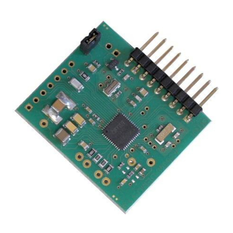
GP30-DEMO-US / GP30-DEMO-US-F01 reference board,
based on TDC-GP30YD (-F01) in QFN32 package
PicoProg Lite with USB-C –USB cable
Figure 1: Functional Blocks
Please download the software for the kit from https://downloads.sciosense.com/tdc-gp30/ and
look for the latest revision of TDC-GP30_EvalSW.
1.1 Ordering Codes
Table 1: Pin description
Ordering code
Part Number
Description
GP30-DEV-KIT
220260003
TDC-GP30YD Demo kit including PicoProg Lite and cable
GP30-DEV-KIT-F01
220260006
TDC-GP30YDF01 Demo kit including PicoProg Lite and cable

4
GP30YD_DK SC-001776-UG-4 / 2023-05-16 / Production
CONTENTS PAGE
GP30-DEMO-US
220260002
TDC-GP30YD Reference board
GP30-DEMO-US-F01
220260005
TDC-GP30YD-F01 Reference board
2Quick Start Guide
This section describes how to quickly set up the GP30-DEV-KIT, establish basic operation and make
measurements.
2.1 Install the Software
It is crucial to install the software before connecting the evaluation kit to your computer. A default
driver loading of your OS may interfere with correct installation.
•Download the latest zipped software installation package to the desired directory.
•Unzip the package to the desired directory.
•Open “setup.exe” from the unzipped directory.
•Follow the instructions on the screen.
2.2 Install the Hardware
•Make sure software is installed correctly before proceeding with this step!
•Connect your computer with the PicoProg Lite using USB cable.
•Connect PicoProg Lite and the evaluation kit reference board.
•The green LED on the evaluation kit should be on.
•Connect your spool piece to US_UP and US_DOWN
2.3 Quick Start for Initial Measurements
From the “Start” menu, go to “All Programs” and then to the “ScioSense” directory. Double click the
“GP30_v2_0” icon (or newer versions, if available) to begin execution of the evaluation software.
The following screen should appear:

GP30YD_DK SC-001776-UG-4 / 2023-05-16 / Production
5
CONTENTS PAGE
Figure 2: Functional Blocks
•Click the “Verify Interface” button to confirm communication between PicoProg Lite and
TDC-GP30 is working. Both fields, “Pico Prog Lite FW version” and “Comm. With GP30 OK?”,
should become green.
•Next, open our initial configuration GP30Y_config_default_03 and download it into the chip,
pressing “Write Config”.
•Connect your spool piece to pins US_UP and US_DOWN. Depending on the outline of the
transducers changes of the configuration will be necessary.
•Press “Start Measurement” to begin measuring.
At this point, after successful completion of the above steps, a basic operation of the DEV kit should
be possible. The following sections provide a detailed description of the hardware and software for
advanced operation.

6
GP30YD_DK SC-001776-UG-4 / 2023-05-16 / Production
CONTENTS PAGE
3Hardware Description
3.1 Introduction
The GP30-DEV MODULE board, shown in Figure 3, is a front-end for a water or heat meters. The
transducers and temperature sensors are directly connected to this board. It comes with a 32.768 kHz
quartz (X2) and a 4 MHz ceramic oscillator (X1). All ports of TDC-GP30 are available. Additional patch
fields allow an easy extension with additional circuits. Those can be amplifiers or analog switches
for operation in gas meter mode.
Figure 3: GP30-DEV MODULE
3.2 Communication Interface
The PicoProg Lite board is a USB-to-SPI converter box that interfaces all UFC evaluation systems.
The PicoProg Lite is registered by the operating system initially as “PicoProg LITE V1.0”. To confirm,
open “Control Panel” of your OS and click on “Devices and Printers” icon. The USB driver will be
listed in “Unspecified” driver section.
The flat connector includes the power lines and the SPI or UART communication lines. The
development kit with PicoProg Lite does not support UART communication.
On the demo board the communication interface is initially selected to SPI (by solder bridge LJ2).
Pin VCC_LEVEL is the voltage feedback for the former PICOPROG level shifters and is no longer used
with PicoProg Lite.
Piezo
D U
PT1000
C H
GND VCC
INIT
MISO
SCK
MOSI
SSN
-
VCC_LEVEL
Pulse
Interface

GP30YD_DK SC-001776-UG-4 / 2023-05-16 / Production
7
CONTENTS PAGE
4Software Description
4.1 Measurement
When started, the software comes up with the main window, showing the “Measurements” tab.
Figure 4: Main Window
4.1.1 First Step with Measurement Control Elements
A good first step is to load a working configuration and make measurements in frontend mode
(without using the internal 32-Bit µP). ScioSense provides a sample configuration file named
GP30Y_config_default_03 which typically works well with DN20 spool pieces.
Load Configuration File: File menu →Open Config →choose appropriate configuration file
1. Press “System Reset” button. Now the Pico Prog Lite FW version field should get green
and the appropriate version should be displayed (1.2.1 or higher). Further, “Comm GP30
OK?” should get green to show that communication with TDC-GP30 works.
2. If watchdog is not disabled by “System Reset”. Button press “Disable Watchdog” button.
3. Press “Write Config” button to download the configuration settings into TDCX-GP30.
4. Press “Start Measurement” button. Now the chip starts to measure and the software
displays the results in the table “Time of Flight Measurements”.
The user can now modify the configuration to fit it to his needs. Having done this, the user can store
his own configuration files.

8
GP30YD_DK SC-001776-UG-4 / 2023-05-16 / Production
CONTENTS PAGE
4.1.2 Time of Flight Measurement Results
GP30 stores the first 8 hits of every TOF direction separately and also the averaged sum of all
measured hits calculated by UI (in blue). These 9 results are displayed for both directions, as we call
them up and down. The evaluation software additionally calculates the difference (in blue) between
up and down stream, DIFF-TOF. In total, all 27 results are displayed in the “Results” column.
In the “Average” column the user can set the sample size for the averaging (<1000). The software
calculates the rolling average of the results accordingly. In “Std. Dev.” column the standard
deviation, calculated over a variable sample size, is displayed. The number of samples can be chosen
(e.g. 100).
The same is done with the amplitude values of the receiving signals and the pulse width ratio between
first hit and start hit. The values for both directions are displayed.
Information: The application of the highspeed calibration is off by default. This is more convenient
when comparing measurement data. But when collecting data for calibration it is strongly
recommended to have this active.
Figure 5: HS Clock Calibration
A graph to display TOF measurement results opens in a separate window by pressing “TOF Graph”
button. It is possible to activate up to four plots. Each plot has various selections, e.g. TOF1UP,
TOF2UP etc.. Always averaged values are displayed.
Figure 6: TOF Graph

GP30YD_DK SC-001776-UG-4 / 2023-05-16 / Production
9
CONTENTS PAGE
The measurement data can be exported into text files, either the main values for calibration only,
or the full data.
Figure 7: Data Export for Calibration
Figure 8: Data Export Complete
4.1.3 2-Wire Temperature Measurement Results
A graph to display temperature measurement results opens in a separate window by “Temperature
Graph” button, similar to TOF graph.
Figure 9: Temperature Measurement Results Graph (previous UI)

10
GP30YD_DK SC-001776-UG-4 / 2023-05-16 / Production
CONTENTS PAGE
4.2 Ultrasonic Measurement Control
In this tab the user makes all settings for an appropriate ultrasonic measurement. They group as
follows:
•Time of Flight Sequence Control
•Time of Flight Hit Control
•Amplitude Measurement Control
•Transducer Interface Options
Figure 10: Ultrasonic Measurement Control Tab
The meanings of the various settings are displayed in clear text. For more details about the register
settings please refer to the GP30 manual.

GP30YD_DK SC-001776-UG-4 / 2023-05-16 / Production
11
CONTENTS PAGE
4.3 Temperature Measurement Control
All settings for an appropriate temperature measurement are done in this tab, which are grouped as
follows:
•Sequence Control
•Measurement Control
•Temperature Measurement Cycle Time
Figure 11: Temperature Measurement Control Tab
The meanings of the various settings are displayed in clear text. For more details about the register
settings please refer to the GP30 manual.

12
GP30YD_DK SC-001776-UG-4 / 2023-05-16 / Production
CONTENTS PAGE
4.4 General Control
The “General Control” tab covers configuration settings for
•Task sequencing
•High speed clock control
•Voltage measurement
•CPU handling
•Timer settings
Figure 12: General Control Tab
The meanings of the various settings are displayed in clear text. For more details about the register
settings please refer to the GP30 manual
4.4.1 Firmware
In case the TDC-GP30 has firmware, setting flag “Enable post processing” turns on the CPU (flow
meter mode). Having this not set, the GP30 runs as front-end in time conversion mode.

GP30YD_DK SC-001776-UG-4 / 2023-05-16 / Production
13
CONTENTS PAGE
4.5 Interfaces
The “Interfaces” tab covers configuration settings for
•Pulse interface including test option
•EEPROM interface
•GPIO control
•UART remote interface.
Figure 13: Interfaces Tab
The meanings of the various settings are displayed in clear text. For more details about the
register settings please refer to the GP30 manual.
4.5.1 Pulse Interface
The pulse interface needs an appropriate firmware in the chip. The settings in the evaluation
software only generate an artificial pulse to test the general functionality. The output is not
related to any measurement.
4.5.2 UART
The UART is not supported in this software version.

14
GP30YD_DK SC-001776-UG-4 / 2023-05-16 / Production
CONTENTS PAGE
4.6 Interrupt & Error Handling
On this tab error indicators and interrupt sources for remote interface can be selected.
Figure 14: Interrupt and Error Handling
The meanings of the various settings are displayed in clear text. For more details about the
register settings please refer to the GP30 manual.
4.7 acam
On this tab specific parameters are displayed, but for ScioSense internal use and analysis only.

GP30YD_DK SC-001776-UG-4 / 2023-05-16 / Production
15
CONTENTS PAGE
4.8 Firmware Parameters and Firmware Error Counters
Those two tabs display and allow editing of parameters related to the ScioSense flow firmware.
They are of use only for TDC-GP30-F01.
For details please refer to the application note TDC-GP30-F01 Flow Firmware (SC-001268-AN).
Figure 15: Firmware Parameters Tab
Figure 16: Firmware Error Counters

16
GP30YD_DK SC-001776-UG-4 / 2023-05-16 / Production
CONTENTS PAGE
5Software Menu
Beside main window, the software menu allows the opening of other windows. There are some menu
items which are redundant to available buttons of main window.
5.1 File
•Open Config
This dialog box allows the path selection of a configuration file, covering the register
settings, necessary for a proper configuration of the GP30. After opening this file, the
control settings are updated in the GUI.
•Save Config
This menu item allows the saving of the current GUI control settings into a configuration file
•Close
Close all open windows of the GP30 Evaluation software.
5.2 Tools
•Run Measurement
Same function as “Start/Stop Measurement” button in “Measurement” tab of main window.
•TOF Graph
Same function as “Open TOF Graph” button in “Measurement” tab of main window.
•Temperature Graph
Same function as “Open Graph” button for temperature measurement in “Measurement”
tab of main window.
•RAM Memory
Opens a window which allows single write and read accesses to random access area for
addresses 0x000 –0x0FF.
The random access area from 0x100 –0x17F, containing the firmware data, can be accessed
separately by “Firmware Download” window
Figure 17: Firmware Parameters Tab

GP30YD_DK SC-001776-UG-4 / 2023-05-16 / Production
17
CONTENTS PAGE
•Registers
Opens a window, which shows the registers important for a proper configuration setting of
the GP30. In the left column, the register contents correspond to the settings done in tabs
of GUI main window. If the button “Read GP30 Register Settings” is pressed, the
configuration settings located in TDC-GP30 registers are displayed in the right column, by
pressing “Read and Transfer” button, the register settings in the tabs of main window and
in the left column of this window are updated with the register settings from right column.
Figure 18: Registers
Remote Commands
This window summarizes some additional commands, which can be executed via remote interface.
System Reset: Executes a complete system reset of GP30. Same function as “System Reset” button
in “Measurement” tab of main window
•System Init: Same function as “System Reset” without clearing the configuration (CR_...) and
the system handling (SHR_...) register.
•CPU Init: Clears the CPU block in GP30
•SV Init: Clears the supervisor block in GP30
•FEP Init: Clears the frontend processing block in GP30
•Request/Release Bus Master: Allows the request of the bus master in GP30, e.g. if the random
access bus is blocked by a deadlock, caused by an improper firmware download.
•Measure Cycle Timer Off/On: Stop & start of the measure cycle timer
•Clear Interrupt Flags: Clears all bits in SRR_IRQ_FLAG register
•Communication Request: Allows an asynchronous demand by remote controller to get an
interrupt by GP30, signalizing the time for remote communication.

18
GP30YD_DK SC-001776-UG-4 / 2023-05-16 / Production
CONTENTS PAGE
•General Purpose Request: Allows an asynchronous request by remote controller to initiate a
general purpose handling in in firmware of integrated GP30 CPU.
Figure 19: Remote Commands
5.3 Firmware
•Assembler
The TDC-GP30 assembler is integrated into the GP30 evaluation software. It is opened in the
Firmware menu of the main program:
Figure 20: Firmware Menu
The following window comes up:

GP30YD_DK SC-001776-UG-4 / 2023-05-16 / Production
19
CONTENTS PAGE
Figure 21: Assembler Window
This is a comfortable editor with syntax highlighting, search and replace, copy and paste functions.
Under menu item “Assembler” the user finds the compile and download options. The download option
effects, that “Firmware Download” window is opened (see also below).
Whether the call of these functions was successful or not is indicated by the messages at the bottom
of the assembler window.
•Firmware Download
This window allows the download of the user code and firmware data, including the configuration,
to the non-volatile memory. In case the bootloader release code is set, the configuration from the
FW Data 2 section is copied into the configuration registers.
“Firmware User Code” is either one of ScioSense firmware examples, either the customers code or
in case of chips with ScioSense firmware (TDC-GP30-F01) the open source part. The FW Data 1 and 2
include firmware relevant coefficients and the configuration. The figure below shows an example for
anTDC-GP30-F01 application. As free part of the user code firmware GP30Y_A1.D2.11.04.hex is
loaded. For the configuration and flow calculation data file GP30Y_A1.A2.11.04.dat is loaded.

20
GP30YD_DK SC-001776-UG-4 / 2023-05-16 / Production
CONTENTS PAGE
Figure 22: Firmware Download
•With “Check Status Flag”, the watchdog and the lock state of the GP30 can be checked.
Please make sure that the watchdog is disabled before starting a download or other
transactions in this window.
•In the “Firmware User Code” section, a firmware user code file (*.hex), which is typically
generated by the assembler tool and intended for the user part of 4kx8 Program NVRAM,
can be loaded by pressing “Open File”.
•In the “Firmware Data” section, a firmware data file (*.dat), which is intended for the
128x32 Data NVRAM, can be loaded by pressing “Open File”. This section also contains some
additional transfer options from GUI to FW Data 2 fields and from GP30 back to FW Data 2
fields. The configuration can be exchanged between the GUI of the evaluation file and the
data file. Calibration can also be exchanged between GUI and data file.
•By pressing “Download FW Code & Data” both files are stored in the corresponding NVRAMs.
This action takes a few seconds. After the download, both files are located in the volatile as
well in the non-volatile part of the appropriate NVRAMs. The download can be combined
with a lock option of the firmware.
•When pressing “Download FW Code & Data” any running firmware program is stopped. If a
new proper auto running firmware program is downloaded, this firmware can be started
again by performing a system reset. A select box allows to reset and restart measurement
automatically after download.
•The last four addresses of the FW Data 2 section contain the checksums which are stored to
GP30 when downloading firmware to GP30. These fields are directly updated, when
firmware files are loaded or content of firmware data fields are changed.
•Pressing the “Verify FW” button after downloading compares the content of the NVRAMs
with the given files by their checksums. The software calculates the checksum of the given
files and reads the calculated checksums of GP30 as well as the stored checksums at the
end of FWD2 section. Note: The firmware data file word 127 is by default empty, not
knowing the checksum of the on-chip ScioSense firmware.
This manual suits for next models
1
Table of contents
Other ScioSense Microcontroller manuals