Essilor Neksia User manual

User Manual


CONTENTS
INTRODUCTION 7
I. FIRST STEPS ITH NEKSIA 9
1. Descriptive diagrams 10
2. Connection to an edger 11
3. Using the tracer-centerer-blocker 12
a. Turn on and turn off the tracer-centerer-blocker 12
b. Using the touch screen and keypads 12
c. ork screen 14
II. TRACING 15
1. The tracing environment 16
a. Menu screen 16
b. Jobs and working modes 18
c. Displaying the binocular view 20
2. Shape management and storage 22
a. Menu screen 22
b. Job list 24
c. Creating a job 24
d. orking in current job mode (job A) 25
3. Tracing a rimmed frame 26
4. Tracing a high-base frame (option) 27
5. Tracing a pattern, demo lens or recut lens 30
a. Optical tracing (option) 30
b. Mechanical tracing 32
c. Inputting the curve and the frame base after monocular tracing 35
III. CENTERING 39
1. Centering environment 40
a. Menu screen 40
b. Call a shape (if the connection to Tess is activated) 42
c. Using the tripods 43
d. Centering modes 43
e. Centering help 44
2. Centering a single vision lens 44
3. Centering a progressive lens 47
a. Centering a progressive lens using re-marked micro-engravings 47
b. Centering a lens using manufacturer markings 50
4. Centering bifocal / trifocal lenses 52
5. Centering an executive lens 54
6. Centering a mid-distance lens 56
a. Centering a lens using re-marked micro-engravings 57
b. Centering a lens using manufacturer markings 59
7. Centering for a high-base frame 61
8. Blocking a lens 61
a. Preparing blocking 62
USER MANUAL> CONTENTS

b. Block the lens 63
IV. MODIFYING THE LENS SHAPE 65
1. Menu screen 66
2. Modifying a shape 67
a. Enlarging, reducing or rotating a shape 67
b. Free-form modification 70
c. Retouching a shape 71
3. Archiving / saving a shape 72
V. PREPARING A DRILLED JOB 73
1. Legend screen 75
2. Configuring a drilling point 78
a. Creating a drilling point 78
b. Delete one drilling point 79
c. Dimensioning a drilling point 79
d. Adjusting the position of a drilling point 80
3. Drilling models 83
a. Importing a model 83
b. Saving a model 84
VI. PREPARING LENS EDGING 87
1. Menu screen 88
2. Edging configuration 90
VII. TRACER-CENTERER-BLOCKER CONFIGURATION 91
1. Configure the tracer-centerer-blocker 92
a. Time, date and language 92
b. Options 93
c. Connections 94
d. Screensaver and brightness of the work area 95
2. Customize the tracer-centerer-blocker, 96
a. orking modes and display precision 97
b. Decentration mode 98
c. Action bar 99
d. Brightness 101
3. Restoring the factory settings 102
VIII. MAINTENANCE & SERVICING 103
1. Carrying out the autotests 104
2. Check and calibrate (remote lens edging option) 105
a. Check and calibrate the tracing table (option) 105
b. Check and calibrate the blocking arm 108
c. Calibrate the touch screen 110
3. Make a backup of the jobs and display configuration 110
4. Statistics and technical history 113
a. Tracer-centerer-blocker statistics 113
b. Technical log and errors 114
5. Maintain and clean the tracer-centerer-blocker 115
a. Precautions required 115
b. Cleaning the centering chamber glass 115
USER MANUAL> CONTENTS

TECHNICAL DATA 117
1. Tracer-centerer-blocker 118
2. Environment 119
GENERAL INFORMATION 121
1. Symbols 122
2. Modifications 122
3. Declaration of conformity 122
4. Copyright 123
5. Materials and products 123
6. Safety instructions: 123
7. Electromagnetic waves 124
GLOSSARY 125
USER MANUAL> CONTENTS


INTRODUCTION
To take full advantage of the functions of your tracer-centerer-blocker, documentation is available in:
•the introduction guide provided at the time of installation
•the user manual, present on the CD-ROM
The screens may vary according to the edger connected to the tracer-centerer-blocker. This documentation
was produced with a connection to the Neksia edger.
USER MANUAL> INTRODUCTION
7
Neksia > v1-02-14

Neksia > v1-02-14
8
USER MANUAL> INTRODUCTION

I. FIRST STEPS ITH NEKSIA

This chapter contains all the information concerning a first use of the tracer-centerer-blocker:
•description of the tracer-centerer-blocker (F p.10)
•connection to an edger (F p.11)
•using the device (F p.12)
1. DESCRIPTIVE DIAGRAMS
This section contains the descriptions and list of accessories of the tracer-centerer-blocker:
1. Screen
2. Blocking arm
3. Centering chamber
4. Tripod
5. Tracing table
6. ON/OFF b tton
7. Connectors
8. Man fact rer plate
1. RS232 (edger) port
2. Barcode reader port
Neksia > v1-02-14
10
USER MANUAL> I. FIRST STEPS ITH NEKSIA

3. RS232 (PC) port
4. RJ45 Ethernet port
5. USB port
Accessories
Transport wedges to be kept
Use accessories
•Tripod&
•Recut lens tripod&
•Stylus
•hite felt tip marker
•Staedler permanent felt-tip pen
•Bag of 22 mm posiblocks
•Bag of 18x14 mm posiblocks
•Roll of 22 mm pads
•Roll of 18x14 mm pads
Tracing table accessories
•Pattern holder
•Pattern holder tip and holding screw
•Set of 2 small B-dimension wedges
Options
•Barcode reader
•Roll of barcode labels
•Table calibration pack
Connection accessories
•220 V power cable
•RJ45 cable for the tracer-edger connection
2. CONNECTION TO AN EDGER
To connect the tracer-centerer-blocker to an edger, use the RJ45 cable (Neksia/Mr Orange edgers) or RS232
cable (Jess/Jessie /JessD/Kappa edgers) provided with the edger.
For the RS232 cable, refer to the labels indicating the direction of connection.
SIDE TRACER SIDE EDGER
USER MANUAL> I. FIRST STEPS ITH NEKSIA
11
Neksia > v1-02-14

3. USING THE TRACER-CENTERER-BLOCKER
In this section, you will find all the information concerning the following:
•turning the tracer-centerer-blocker on and off, (F p.12)
•use of the touch screen and keyboards (F p.12),
•description of the work screen (F p.14).
a. Turn on and turn o the tracer-centerer-blocker
Switching on
Press the ON/OFF button located at the top right on top of the screen.
The tracer-centerer-blocker is initialized.
A beep indicates that initialization was successful.
The tracer-centerer-blocker is ready to be used when the initial screen is displayed.
Switching o
Press:
•briefly on the ON/OFF button, located at the top right at the top of the screen or
•on > , from the work screen.
Do not press on the ON/OFF button for several seconds. This would result in shut-down of the
machine and an error message would be displayed at the next switch-on.
A confirmation message is displayed.
Select to confirm.
The tracer-centerer-blocker is switched off.
Extended period o non-use
During a prolonged period of non-use (several days), it is preferable to turn off the tracer-centerer-
blocker by unplugging the mains power supply.
b. Using the touch screen and keypads
Using the touch screen
Use the stylus on the touch screen.
You can also touch the screen with your finger.
Neksia > v1-02-14
12
USER MANUAL> I. FIRST STEPS ITH NEKSIA
>
>
>
>
1
1
2

•If the response area does not correspond to the position of the key, you need to calibrate the touch
screen. For further information, refer to the section Maintenance and servicing > Check and calibrate
> Calibrate the touch screen (F p.110).
•Never press hard on the screen as this could break it.
•Never press on the screen with sharp objects such as pens, scissors, clamps, etc.
•Screen breakage is not covered by the guarantee.
On each screen, press the icon-buttons to access the desired menus and functions.
Using the keypads
hen you need to input or modify data, two types of keypads are automatically displayed, according to the
information to be input.
•The numeric keypad is displayed for the input of values.
• Reset the fields
• Back
• Confirm
• Cancel and go back to the work screen
•The alphanumeric keyboard is displayed for storing, calling and searching for jobs.
•Job&ID&
• Job reference (alphanumeric characters)
USER MANUAL> I. FIRST STEPS ITH NEKSIA
13
Neksia > v1-02-14

c. Work screen
At the end of initialization of the tracer-centerer-blocker, the following screen is displayed:
1. Work screen indicator
2. Job information
3. Settings
4. Devices connected
5. Active eye and information on the shape
6. Work area
7. F nction b ttons
8. Actions available for the c rrent screen
Detailed unctions
For more information, consult the section Perform a trace > Tracing environment> Captioned screen.
(F p.40)
Neksia > v1-02-14
14
USER MANUAL> I. FIRST STEPS ITH NEKSIA

II. TRACING

This chapter describes the procedures for the tracing of all types of frames, patterns, demo lenses and recut
lenses:
•Description of the tracing environment (F p.16)
•Manage and store shapes, (F p.22)
•Trace a rimmed frame (F p.26) (including high-base frame)
•Trace a high-base frame (F p.27)
•Trace a pattern, demo lens or recut lens (F p.30).
1. THE TRACING ENVIRONMENT
This section describes the tracing screen and explains how to manage the jobs:
•description of the tracing screen, (F p.16)
•jobs and working modes (F p.18)
•displaying the tracing completed in binocular mode (F p.20)
a. Menu screen
1. Dimensions display
◦A: A-dimension
◦B: B-dimension
◦D: D-dimension
◦E: Greater radius from the boxing center
◦P: Perimeter
2. F nction b ttons
◦ Tracing
◦ Centering
Neksia > v1-02-14
16
USER MANUAL> II. TRACING

◦Edging preparation
◦Shape management
◦Machine shutdown
3. Tracing mode
◦Rimmed frame (including high-base frame)
◦High-base frame (option)
◦Optical tracing (option) (patterns, demo lenses or recut lenses)
4. Type of tracing
◦Symmetric binocular tracing&
◦Asymmetric binocular tracing&
◦Right-eye monocular tracing
◦Left-eye monocular tracing
◦Single monocular tracing of the right eye (blocking and possible edging of the right eye
only)
◦Single monocular tracing of the left eye (blocking and possible edging of the left eye only)
5. Frame material or optical tracing type
For mechanical tracing:
◦Metal frame: high-precision tracing, with feeling of the groove cross-section
◦Plastic frame
◦Optyl frame, for particularly flexible frames
For optical tracing (option):
◦Demo lens / Recut lens
◦Pattern
For mechanical tracing of demo lenses, recut lenses or patterns, the tracer automatically detects the
pattern holder inserted in the tracing table.
6. New Job
For more information on jobs&, refer to the section Tracing > Shape management and storage (F p.22).
7. Tracing cycle initialization
USER MANUAL> II. TRACING
17
Neksia > v1-02-14

Always browse from left to right: depending on your selection, certain menus will be available while
others will not.
You can activate or deactivate types of tracing in the configuration screen.
b. Jobs and working modes
Jobs
A ‘job’ incorporates all the necessary actions for assembling a pair of glasses. It can be managed in two
ways:
•saving: allocate an ID and a reference to the job to save it and re-use it later.
◦Automatic job archiving
◦Mandatory in the tracing - tracing work mode
•without saving: working in current mode (job identification by the letter A) makes it possible to
process a job quickly without saving it. It is necessary to complete the treatment cycle of the current
job before starting a new one.
Working modes
There are four working modes for managing your jobs:
•tracing - centering - preparing edging mode
•tracing - preparing edging - centering mode (by default)
•tracing - tracing - centering - preparing edging mode
•tracing - tracing - preparing edging - centering mode
The selected work mode is shown in the information bar, to the left of the Essilor logo. You can change it in
the tracer settings.
Working in tracing - centering - preparing edging mode
At the end of a tracing, the tracer-centerer-blocker displays the centering screen automatically
then the edging preparation screen.
You can fully process a job before proceeding to the following:
1. tracing or retrieving a job from the database
2. changing the shape and drilling position if necessary
3. centering
4. lens blocking
5. edging preparation
To activate this working mode, select the following parameters in the configuration screen: (F p.97)
Neksia > v1-02-14
18
USER MANUAL> II. TRACING

Work in tracing - preparing edging - centering mode
At the end of tracing preparation, the tracer-centerer-blocker automatically displays the edging
preparation screen then the centering screen and proposes the posiblock adapted to the prepared edging.
1. Tracing or recovering a job from the database
2. Edging preparation
3. Changing the shape and drilling position if necessary
4. Centering
5. Lens blocking
To activate this working mode, select the following parameters in the configuration screen (F p.97):
Work in tracing - tracing - centering - preparing edging mode
At the end of a tracing, the tracer-centerer-blocker displays the tracing screen.
•You can perform several tracings in succession.
•The tracings are saved under the job number that you have assigned to them.
•Shape modification, centering, blocking and edging preparation are processed later.
•All jobs must be saved.
•After a job call the centering screen appears automatically, followed by the edging preparation screen.
•You can access the centering screen at any moment to centre the lens that corresponds to the active
shape:
> select then .
To activate this working mode, select the following parameters in the configuration screen: (F p.97)
Work in tracing - tracing - preparing edging - centering mode
At the end of a tracing, the tracer-centerer-blocker displays the tracing screen.
•You can perform several tracings in succession.
•The tracings are saved under the job number that you have assigned to them.
•Shape modification, edging preparation, centering and blocking are processed later.
•All jobs must be saved.
USER MANUAL> II. TRACING
19
Neksia > v1-02-14

•After a job call the edging preparation screen appears automatically, followed by the centering screen.
•You can access the edging preparation screen at any time:
> select then .
To activate this working mode, select the following parameters in the configuration screen: (F p.97)
c. Displaying the binocular view
Once the tracing is finished, you can display a binocular representation of the job on a 1:1 scale, in order to
check the frame shape and centering.
Three values are displayed above the image:
•the frame base&
•the curve angle&
•the frame thickness
The indicator symbolizes the wearer side view.
In tracing - centering mode, the centering screen is displayed at the end of the tracing:
Select then to access the tracing screen.
The monocular view is displayed by default.
Press to display the binocular view.
Neksia > v1-02-14
20
USER MANUAL> II. TRACING
1
2
Other manuals for Neksia
1
Table of contents
Other Essilor Lathe manuals
Popular Lathe manuals by other brands
Metallkraft
Metallkraft SBM 110-08 operating instructions
Trak Machine Tools
Trak Machine Tools TMC10 Site preparation guide
Milltronics
Milltronics SL12 Series Instruction handbook
Grizzly
Grizzly G0554 owner's manual
HOLZMANN MASCHINEN
HOLZMANN MASCHINEN D460FXL user manual
Promac
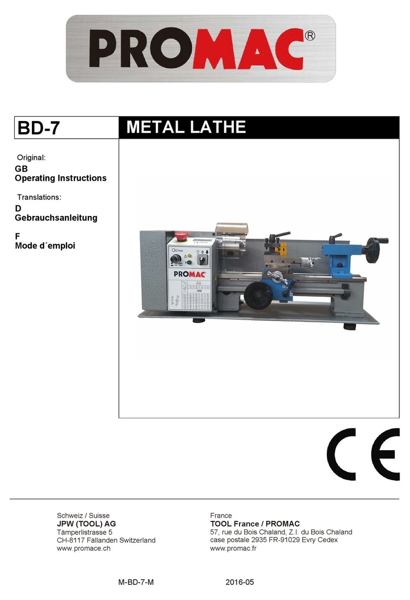
Promac BD-7 operating instructions
