Scotchman CPO 350 User manual

CPO-350
VARIABLE
SPEED
COLD SAW
PRINTED SEPTEMBER 2014

TABLE OF CONTENTS
SECTION DESCRIPTION PAGE #
1.0 INTRODUCTION 4
2.0 SAFETY PRECAUTIONS 4
3.0 WARRANTY 5
4.0 INSTALLATION & SET-UP 6
4.1 Physical Dimensions 6
4.2 Machine Moving Procedures 8
4.3 Physical Inspection 9
4.4 Electrical Requirements 10
4.5 Machine Start-up 15
4.6 Guard Adjustment 16
4.7 Coolant System 18
5.0 MAINTENANCE & LUBRICATION 18
5.1 Lubrication 18
5.2 Cutting Oils & Lubricants 20
5.3 Scheduled Maintenance 21
6.0 MACHINE OPERATION 22
6.1 Installing Blades 22
6.2 Saw Capacities 24
6.3 Selecting The Proper Blade & Cutting Speed 25
6.4 Material Clamping 26
6.5 Miter Locking Device 28
7.0 OPTIONAL EQUIPMENT 30
7.1 Power Vise 30
7.1A Power Vise Set-up & Maintenance 30
7.1B Replacing the Spindle in the Air Vise 32
7.1C Replacing the Seals in the Air Vise 34
7.2 Power Down Feed 36
7.2A Power Down Feed Set-up & Maintenance 36
7.2B Stroke Control Adjustment-Power Down Feed 38
7.2C Guard Adjustment-Power Down Feed 40
7.2D Installing Blades-Power Down Feed 42
7.2E Power Down Feed Trouble Shooting 44
7.2F Power Down Feed Wiring Diagram 45
7.2G Pneumatic Schematic (Power Down Feed) 46
7.3 Material Supply Tracks 48
7.4 Discharge Tracks with Quick-Loc 50
7.5 Special Vise Jaws 52
7.6 Lock-Out Disconnect Switch 52
8.0 TROUBLE SHOOTING GUIDE 52
PAGE 2

TABLE OF CONTENTS
SECTION DESCRIPTION PAGE #
8.1 Electrical Trouble Shooting 52
8.2 Breakage or Excessive Dulling of Blades 52
8.3 Coolant System 53
8.4 Gear Replacement 54
9.0 PARTS LISTS 56
9.1 Saw Head 56
9.2 Vise Assembly 58
9.3 Guard Assembly 60
9.4 Motor Assembly 62
9.5 Electrical Unit 64
9.6 Coolant Pump 66
9.7 Cast Base & Pedestal 68
9.8 Material Stop 30 Inch (76 CM) 70
9.9 Variable Speed Motor Control 72
9.10 Cast Saw Blade Cabinet 74
10.0 OPTIONAL EQUIPMENT PARTS LISTS 76
10.1 Power Vise Assembly 76
10.2 Power Down Feed Assembly 78
10.2A Power Down Feed Controls 80
10.2B Power Down Feed Electric Controls 82
10.2C Guard Assembly (Power Down Feed) 84
10.3 10 Foot (303 CM) Supply Track 86
10.4 Discharge Tracks (48", 84" & 120") 88
10.5 Coolants & Lubricants 90
10.6 Lock-Out Disconnect Switch 90
10.7 Laser Light 92
11.0 STOCK BLADES 94
PAGE 3

1.0 INTRODUCTION
The CPO-350 Variable Speed Cold Saw is designed to cut solids, tubes, flats and other profiles in grades
of material that range from hot and cold rolled steel, annealed tool steels, stainless, aluminum, brass,
copper, synthetics and extrusions. Cold sawing is a process similar to a milling process. In most cases,
this, combined with the self centering vise feature and the variable speed drive, gives a finished cut that
does not require any secondary machining or de-burring. Since milling spindle speeds are used in cold
sawing, there are several things that are required to achieve quality results. The selection of the proper
pitch (number of teeth) on the blade and the proper spindle speed for the type of material being cut are
critical. Proper material clamping and a good quality coolant are also important. Cold sawing has
several advantages over band saws and abrasive saws. Besides the mill quality cut, cold saws have the
ability to generate faster cutoff times than band saws. There are no sparks and excessive noises that are
associated with abrasive cutoff saws. Cold saws also offer the advantage of blades that can be
re-sharpened until the diameter of the blade will no longer cut through the material. The self centering
vise allows for easy changeover to special clamping jaws for profiles and extrusions. Having two spindle
speeds enables the user to cut a wide range of materials. By adding the power vise and power down-feed
options, the saw can be converted to a semi-automatic machine at a very reasonable price.
2.0 SAFETY PRECAUTIONS
1. Any individual operating this machine must be qualified, responsible and well instructed. This
manual is not intended to teach untrained personnel how to operate equipment.
2. NEVER operate this machine with the guard disconnected or removed.
3. Wear eye protection, at all times, when operating or observing this machine in operation.
4. Do not wear loose fitting clothing, gloves or jewelry when operating this machine.
PAGE 4

5. All electrical connections shall be made by a qualified electrician. This machine must be grounded
in accordance with the National Electric Code.
6. Disconnect the machine from the power source before performing maintenance or changing blades.
7. Practice good housekeeping. Keep the area around the machine clean and dry.
8. When sawing, always support long pieces and make sure that the material is properly clamped.
9. Keep the guard, as well as all other parts of the saw, in good working condition. Replace worn parts
promptly.
10. Do not alter or modify this machine in any way without written permission from the manufacturer.
11. This machine is top heavy and must be anchored to the floor.
3.0 WARRANTY
Scotchman Industries, Inc. will, within three years of the date of purchase, replace F.O.B. the factory or
refund the purchase price for any goods which are defective in materials or workmanship, provided the
buyer, at the seller’s option, returns the defective goods freight and delivery prepaid to the seller, which
shall be the buyer’s sole and exclusive remedy for defective goods.
Hydraulic and electric components are subject to their respective manufacturer’s warranties.
This warranty does not apply to machines and/or components which have been altered, changed or
modified in any way or subjected to abuse and abnormal use, inadequate maintenance and lubrication or
subjected to use beyond the seller’s recommended capacities and specifications.
In no event shall the seller be liable for labor cost expended on such goods or consequential damages.
The seller shall not be liable to the purchaser or any other person for loss or damage directly or
indirectly arising from the use of the goods or from any other cause.
No officer, employee or agent of the seller is authorized to make any oral representations or warranty of
fitness or to waive any of the foregoing terms of sale and none shall be binding on the seller.
Any electrical changes made to the standard machine due to local electrical code variation must be paid
by purchaser.
As we constantly strive to improve our products, we reserve the right to make changes
without notification.
This warranty is effective December 1, 2009.
PAGE 5

4.0 INSTALLATION AND SET-UP
ÖCAUTION: THIS SECTION DISCUSSES INSTALLATION, SET-UP AND START-UP
PROCEDURES. PLEASE READ IT THOROUGHLY BEFORE OPERATING THIS MACHINE.
IF YOUR MACHINE IS EQUIPPED WITH EITHER THE POWER VISE OR THE POWER
DOWN FEED OPTION, READ ALL SECTIONS CONCERNING THESE OPTIONS BEFORE
OPERATING THE SAW.
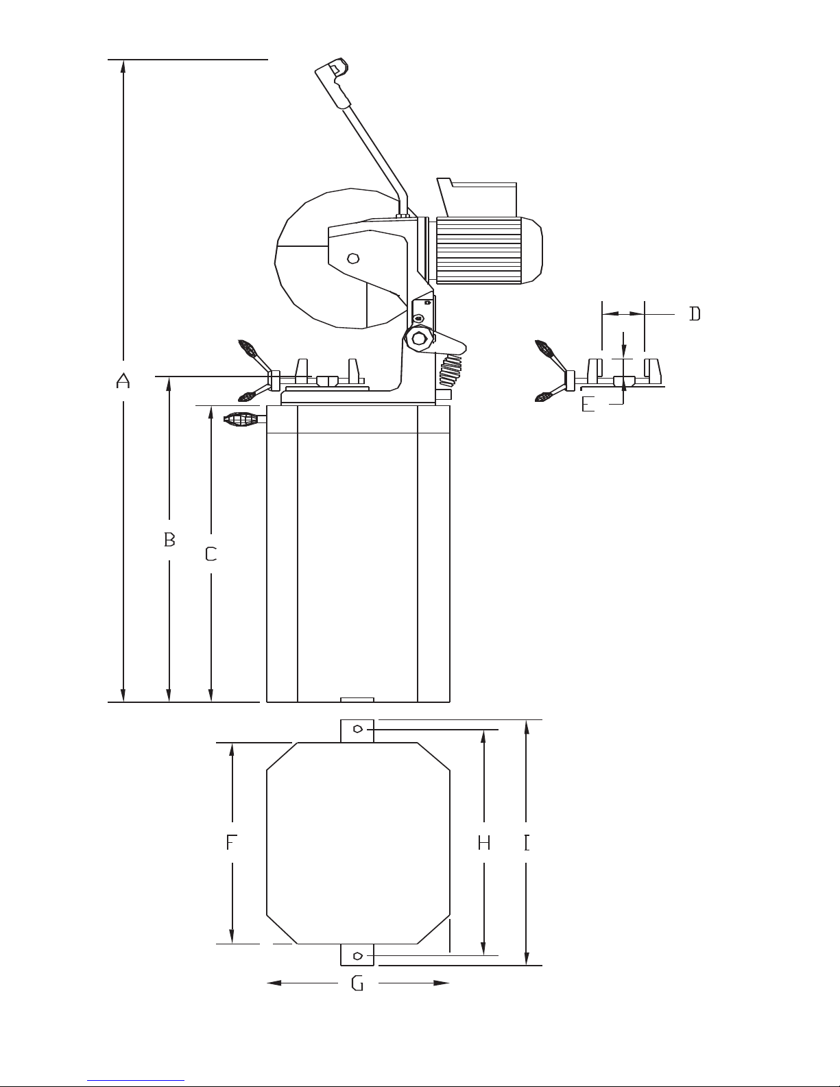
4.1 PHYSICAL DIMENSIONS
SEE FIGURE 1 ON THE FOLLOWING PAGE.
DIMENSIONS INCHES CM
A. HEIGHT 67.5 171.4
B. FLOOR TO VISE 37.5 95.3
C. BASE HEIGHT 32 81
D. VISE OPENING 6 15.2
E. VISE DEPTH 2.75 7
F. BASE WIDTH 21.5 55
G. BASE DEPTH 17.25 44
H. MOUNTING HOLE CENTERS 4.5 62
I. WIDTH 26.5 67
J. WEIGHT CPO-350 VS 525 LBS. 238 KG.
CPO-350 PKPDVS 625 LBS. 284 KG.
PAGE 6
PAGE 7
FIGURE 1
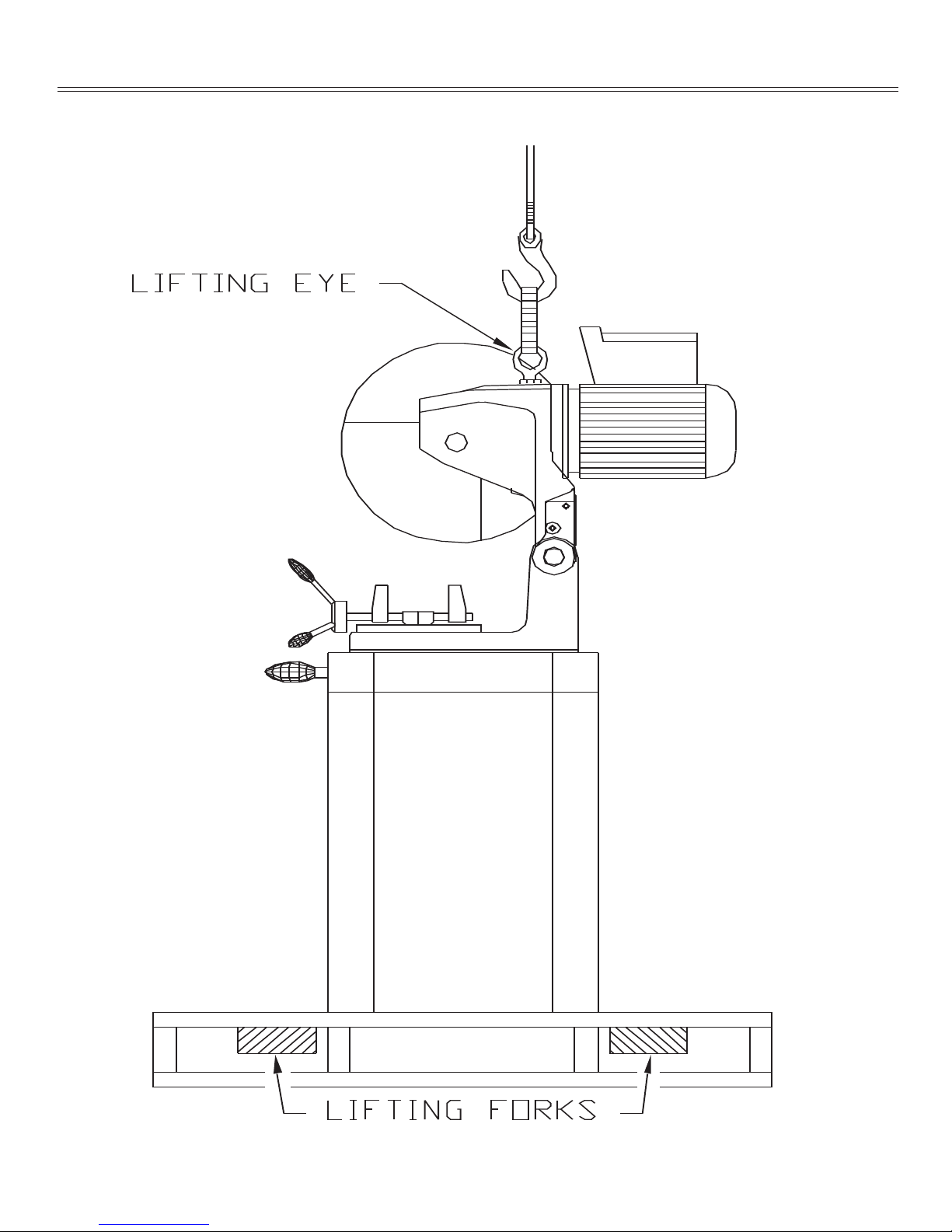
4.2 MACHINE MOVING PROCEDURES
SEE FIGURE 2 BELOW.
PAGE 8
FIGURE 2

This machine is shipped on a pallet and can be moved to the installation location by means of a forklift.
ÖCAUTION: THIS MACHINE IS TOP HEAVY AND MUST BE MOVED WITH CARE, ON HARD
FLAT SURFACES ONLY.
All saws, except models equipped with the power down feed option, are shipped with the head locked in
the DOWN position. Before lifting the machine, release the head by opening the material vise and
allowing it to move to the UP position. Lift the machine, using the lifting eyelet provided. SEE FIGURE
2 ON THE PRECEDING PAGE. Remove the pallet and place the machine in its final location. This
machine is top heavy and must be anchored to the floor.
4.3 PHYSICAL INSPECTION
Once the machine is located, check it for any possible damage incurred in shipment. Remove the lifting
eyelet and install the draw handle.
ÖCAUTION: DO NOT USE THE LIFTING EYELET FOR ANY MACHINES OTHER THAN THIS
SAW. MAKE SURE THAT THE DRAW HANDLE HAS A JAM NUT ON THE THREADS
BEFORE INSTALLING IT ON THE SAW. IF THE HANDLE IS INSTALLED WITHOUT THE
JAM NUT, IT MAY CONTACT THE GEARS INSIDE THE HEAD.
After the draw handle has been installed on manual and power vise machines, remove the cover from the
electrical control box and connect the trigger switch wires. REFER TO FIGURE 3-1.
Remove any other packing material and draw the saw head to its DOWN position to make sure that the
guard opens properly. The guard should close completely when the head is up and open freely as the
head travels down.
If the guard is not functioning properly, REFER TO SECTION 4.6 FOR THE MANUAL MACHINES
OR SECTION 7.2C FOR MACHINES EQUIPPED WITH THE POWER DOWN FEED OPTION.
With the head in the UP position, check the oil level in the gear box through the sight glass in the
casting just below the draw handle.
If your saw is equipped with either the power vise or the power down feed option, REFER TO
SECTIONS 7.1 THRU 7.2, for additional information.
PAGE 9

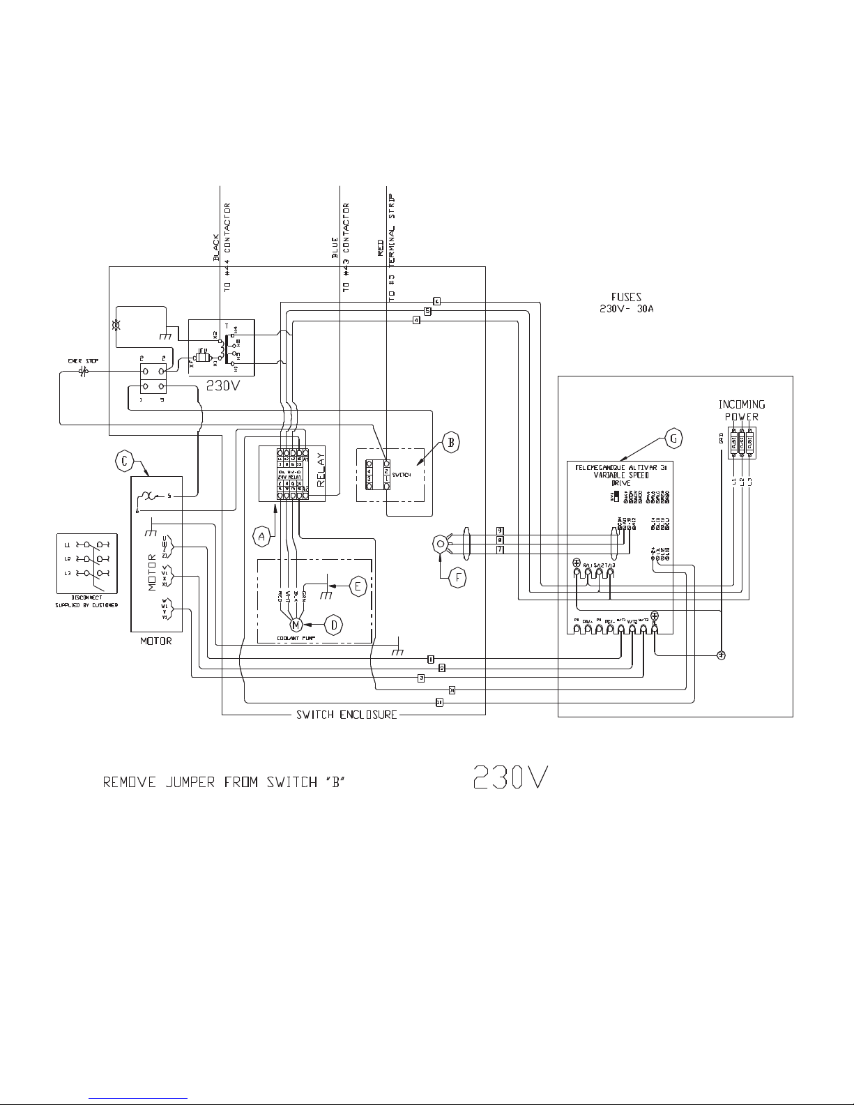
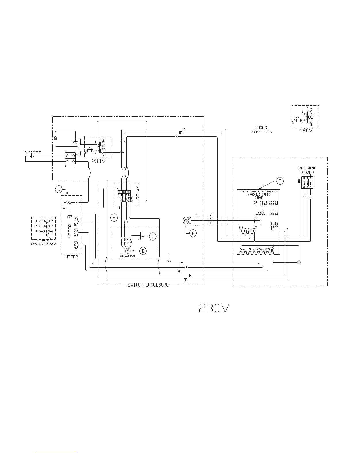
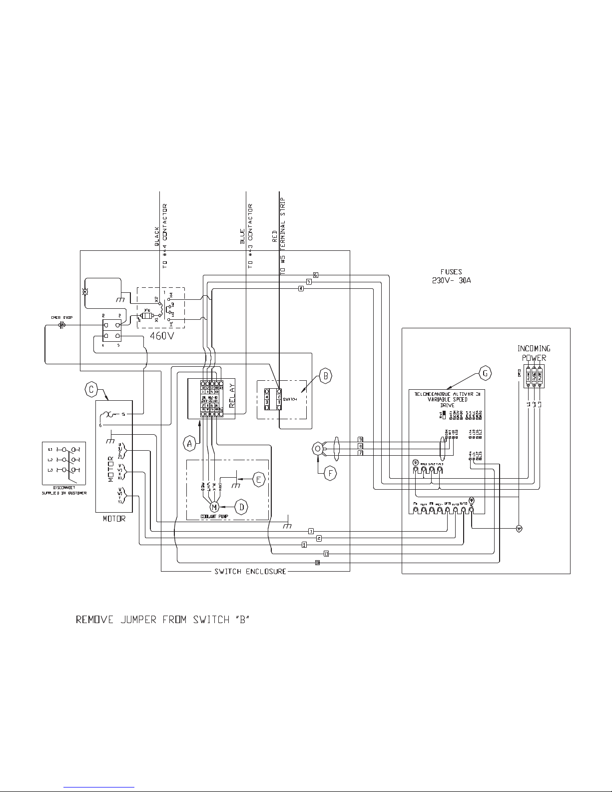
4.4 ELECTRICAL REQUIREMENTS
SEE FIGURE 3-1 THROUGH 3-4 ON THE FOLLOWING PAGES.
ÖCAUTION: TO PREVENT DAMAGE TO THE MACHINE AND DANGER TO THE OPERATOR,
ALL ELECTRICAL CONNECTIONS SHOULD BE MADE BY A QUALIFIED ELECTRICIAN.
THIS MACHINE OPERATES WITH LIQUID COOLANT AND MUST BE GROUNDED IN
ACCORDANCE WITH NATIONAL ELECTRIC CODES.
All machines are wired for three phase power. The motors and coolant pumps are dual voltage and will
operate on either 230 or 460 volts; the Variable Speed Drive is not. If the machine is not the same voltage
as your plant voltage, you will have to replace the variable speed drive, change the primary leads on
the transformer and rewire the motor. To insure satisfactory performance, the supply voltage should be
(+ or -) 10% of the motor voltage rating. Check the motor data tag for full load current requirements.
Single phase motors are not available; however, the Variable Speed Drive can be used as a phase
converter. For supply lines ten feet (303 cm) or shorter, we recommend 12 gauge wire. For lines longer
than ten feet (303 cm), we recommend 10 gauge wire. We do not recommend supply lines over twenty feet
(606 cm) in length.
CPO-350 (11-176 RPM)
MOTOR VOLTAGE FULL LOAD CURRENT HORSEPOWER
208 22 5
230 20 5
460 10 5
PAGE 10
PAGE 11
350 VS POWER DOWN 230 VOLT
SEE PAGE 47 FOR POWER DOWN WIRING.
FIGURE 3-1
PAGE 12
350 VS MANUAL & PK 230 VOLT
FIGURE 3-2
PAGE 13
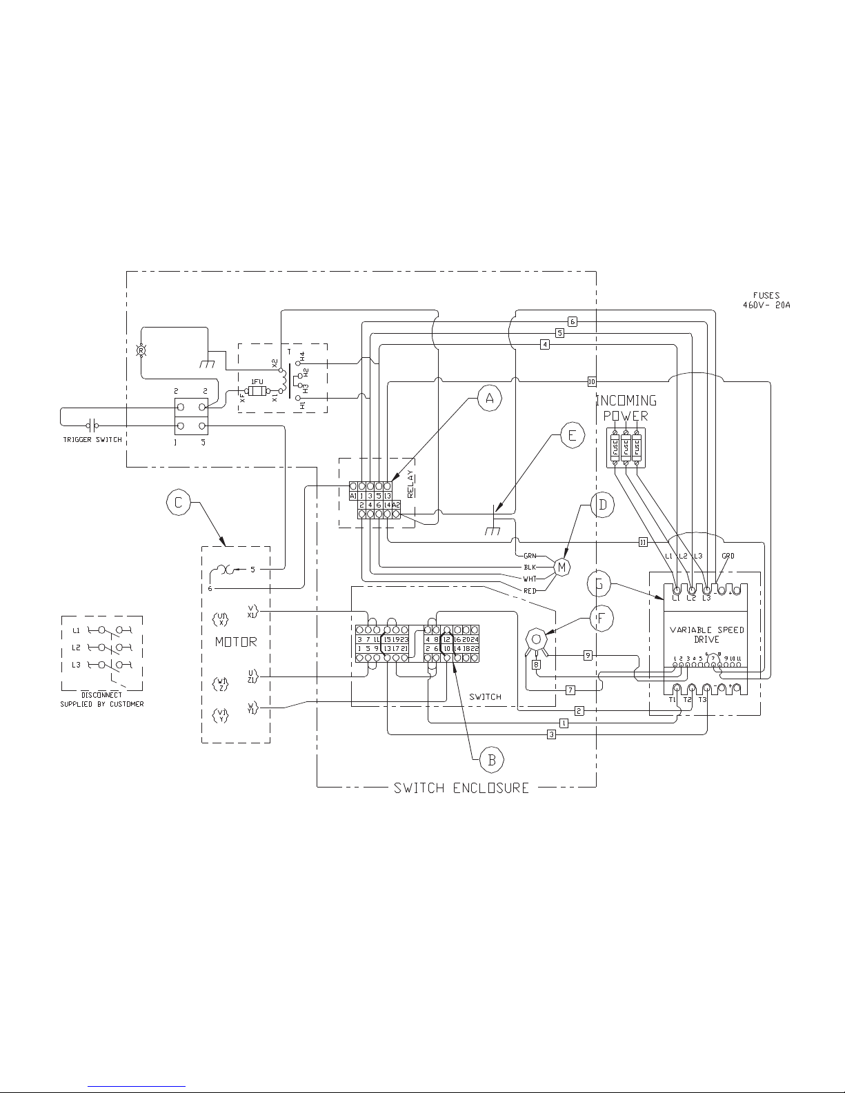
350 VS POWER DOWN 460 VOLT
SEE PAGE 47 FOR POWER DOWN WIRING.
FIGURE 3-3
PAGE 14
350 VS MANUAL & PK 460 VOLT
FIGURE 3-4

4.5 MACHINE START-UP
Before starting this machine, take the time to review the operator’s manual thoroughly, to familiarize
yourself with all of the functions of the machine.
We strongly urge you to follow OSHA directive CFR-1910.147 (effective 09-09-90) regarding lock-out,
tag-out procedures. Keep in mind that the directive refers to all hazardous energy sources, not just
electrical.
On machines equipped with either a power vise or a power down feed, the air supply must also be
disconnected and locked or tagged. Scotchman offers a lock-out switch for this machine as an option, if
your plant is not equipped with lock-out capabilities. If you are interested in this option, REFER TO
SECTION 7.7 or contact your local dealer or the factory.
Do not install a blade on the saw until after it has been powered and cycled several times.
To power manual and power vice machines, use the trigger switch mounted in the draw handle to start
the motor.
To power machines equipped with the power down feed option, turn the Motor switch to the ON position
and depress the foot switch to start the motor. The foot switch can be used to cycle the saw head without
starting the motor, by leaving the motor switch in the OFF position.
We do not recommend using the emergency stop switch to turn the machine off during normal operation.
If the emergency stop switch is used, it must be manually reset by pulling the switch back out.
Always turn the Motor switch to the OFF position when the saw is not in use.
Once the machine has been powered, check the rotation of the spindle. There is an arrow on the guard
showing the proper rotation. If the rotation is not correct, the electrician will have to switch two of the
three line wires.
If the saw is equipped with either the power vise or the power down feed options, SEE SECTIONS 7.1
THRU 7.2, for additional information on electrical and air connections.
The Variable Speed Motor Control has an RPM range of 11 to 176 RPM’s.
PAGE 15

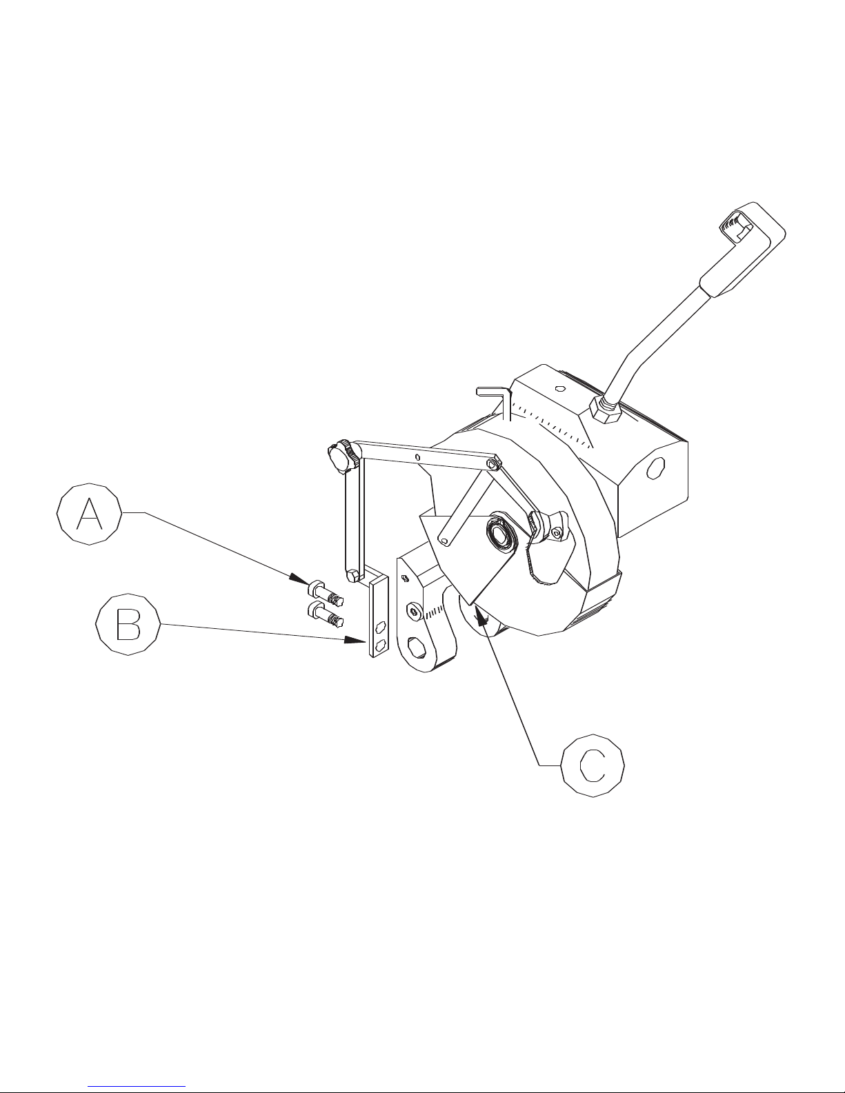
4.6 GUARD ADJUSTMENT-MANUAL MACHINES
SEE FIGURE 4 ON THE FOLLOWING PAGE.
FOR GUARD ADJUSTMENT PROCEDURES ON SAWS EQUIPPED WITH THE POWER DOWN
FEED OPTION, REFER TO SECTION 7.2C.
The proper adjustment of the blade guard on this machine is crucial to the operation of the machine and
the safety of the operator. If the guard will not maintain proper adjustment, check the guard mounting
bolts and rivet joints in the guard and linkage for wear. Replace worn parts promptly.
USE THE FOLLOWING STEPS TO ADJUST THE BLADE GUARD:
1. Turn the power off and disconnect from the power source.
2. With the head in the UP position, loosen the mounting bolts (A) on the linkage mount (B).
3. Manually hold the guard open approximately 1/8 of an inch (3 mm) at point (C).
4. Adjust the linkage mount (B) down until there is tension on the linkage bar. Re-tighten the linkage
mount bolts (A).
5. Manually cycle the head up and down several times, making sure that the guard operates properly.
PAGE 16
PAGE 17
FIGURE 4

4.7 COOLANT SYSTEM
The coolant reservoir has a capacity of ten (10) gallons (37.8 liters). One gallon of coolant is shipped with
the saw. For normal cutting, it should be mixed in a ratio of one part coolant to seven parts water. In
conditions of heavier cutting, the ratio of water should be reduced to five parts. We recommend using
only pure, synthetic, water soluble cutting oils. Petroleum based cutting oils will reduce the life of the
coolant pump considerably. We recommend pre-mixing the coolant before adding it to the saw.
When cutting alloy steels such as stainless steel, we recommend a special mix coolant designed for these
applications. For additional information on available coolants, SEE SECTION 10.6.
5.0 MAINTENANCE AND LUBRICATION
5.1 LUBRICATION
SEE FIGURE 5 ON THE FOLLOWING PAGE.
Before operating the saw, grease the pivot pins (A) and apply penetrating oil to the vise spindle and
guides (B and C). Once a week, grease all of the pivot pins and oil all of the rivet connections on the
guard linkage. Check the level of the fluid in the saw head checking the sight glass in the front of the head
casting. To add fluid, remove the breather plug next to the draw handle. On machines not equipped
with a breather, you have to remove the draw handle and add gear lubricant through this opening.
Clean the chips out of the vise every day and apply penetrating oil to the spindle and guide pins. Clear the
chips with a brush or similar device. DO NOT use compressed air. For additional information if your saw
is equipped with a power vise or power down feed option, SEE SECTIONS 7.1 THRU 7.2.
PAGE 18

PAGE 19
FIGURE 5

5.2 CUTTING OILS AND LUBRICANTS
SECTION 10.6 lists Scotchman’s parts numbers for cutting oils and lubricants.
Using high quality lubricants and oils will greatly increase the life of this equipment.
We recommend using only pure, synthetic, water soluble cutting oil for coolant.
For the saw head, use a Mobil 600W Super Cylinder Oil or equivalent.
On saws equipped with the power down feed, use a Mobil DTE Light, or equivalent, in the reservoir.
On saws equipped with air lubricators, use Mobil DTE Light.
PAGE 20
Table of contents
Other Scotchman Saw manuals

Scotchman
Scotchman SUP-600-NF User manual

Scotchman
Scotchman CPO-315-HFA-CNC User manual

Scotchman
Scotchman CPO-275 User manual

Scotchman
Scotchman CPO-315-HFA-5HP User manual

Scotchman
Scotchman SUP-600-NF User manual

Scotchman
Scotchman CPO-350-NF-5HP User manual

Scotchman
Scotchman CPO-315-RFA-NF User manual

Scotchman
Scotchman SU-280 User manual

Scotchman
Scotchman CPO-315-HFA-NF User manual

Scotchman
Scotchman GAA-500-90 NF User manual


