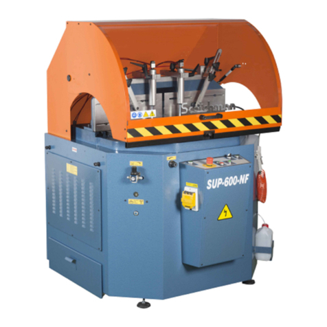
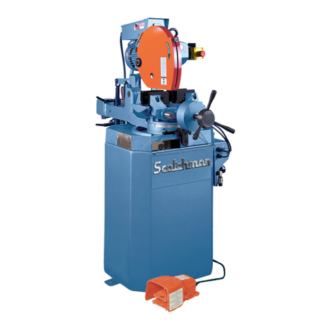
Scotchman SUP-600-NF User manual

You have downloaded a
manual for our
MODEL SUP-600-NF
PRECISION MITER UP-CUT
NON-FERROUS SAW

PRINTED MAY 2021
www.scotchman.com
SCOTCHMAN INDS. - 180 E US HWY 14 - PO BOX 850 - PHILIP, SD 57567 Call: 1-605-859-2542
MODEL
SUP-600-NF
COLD SAW

www.scotchman.com
SUP-600 NF SAW
FIGURE 1
Page 2

BEST
IN THE
BUSINESS
WARRANTY
S
C
O
T
C
H
M
A
N
www.scotchman.com
HYDRAULIC IRONWORKERS
CIRCULAR COLD SAWS
DIGITAL PROGRAMMABLE FEED SYSTEMS
SU-280-G BAND SAW
66 to 176 TON PRESSPRO HYDRAULIC PRESSES
SCOTCHMAN INDS. - 180 E US HWY 14 - PO BOX 850 - PHILIP, SD 57567
Call Toll Free in USA: (800) 843-8844 Call Direct: 1 -605-859-2542 Fax: (800)-843-5545 Email: [email protected]

Page 3
SECTION DESCRIPTION PAGE #
2.4
2.6
Machine Identification Data
Technical Data
Dimensions of the Machine
Cutting Capacity
Noise Level
INSTRUCTIONS REGARDING
INSTRUCTIONS FOR ANCHORING
Anchoring Instructions
Power Supply Connection
Pressure Regulator
Installing the Blade
Cutting Coolant
Pneumatic Oil
INSTRUCTIONS FOR USE
Proper and Improper Use
Function of the Operating Mechanisms
Adjusting the Digital Degrees
General Rules and Safety Checks
RECOMMENDATIONS AND MAINTENANCE
Type and Frequency of Inspections
Qualified Personnel Maintenance & Repair Work
Manufacturer's Recommendations
DRAWINGS AND SCHEMATICS
General Schematic
Power Circuit
Switching Power Circuit
Operating Controls
Pneumatic Schematic
Cast Iron Table & Disc Assembly (Exploded View)
3.0
4.1
4.2
4.0
4.3
4.4
4.5
4.7
5.1
5.0
5.2
5.3
5.4
6.1
6.2
6.0
6.3
7.1
7.0
7.2
7.3
7.4
7.5
7.6
9
8
8
7
6
5
11
10
9
9
16
16
15
15
13
13
13
23
21
19
17
17
16
16
2.3
2.2
2.1
1.1
2.0
1.0 INTRODUCTION
Warranty
GENERAL MACHINE INFORMATION
5
5
4
4
TABLE OF CONTENTS
Rocker Assembly (Exploded View)
7.7
25
Turret Assembly (Exploded View)
7.8
27
Sheet Metal Base (Exploded View)
7.9
29
Protective Shield (Exploded View)
8.0
31
OPTIONAL EQUIPMENT
8.1
33
Power Hood (Standard Equipment Now)
8.2
35
Digital Control of the Cut Height
8.3
37
Digital Angle Display (PART # 1554)
9.0
37
ANGLEMASTER WITH CHIP
7.2A
39
TRANSPORT AND STORAGE
AND SERVICE START-UP
COLLECTOR WIRE LOCATIONS
40
41
2.5 Electrical Data 8
10
4.6 Priming/Adjusting the Coolant Mister
12
12

1.0 INTRODUCTION
The instruction manual represents an integral part of the machine. It must be consulted before, during
and after the machine is put into service, as well as whenever it is considered necessary, thereby
respecting its content in each and every one of its parts.
This is the only way in which the fundamental objectives that have been established on the basis of this
manual will be achieved; such as, accident prevention and making optimal use of the machine features.
Within the framework of this manual, all aspects regarding safety and accident prevention on the job
while using the machine have been considered in every detail, herein highlighting the information that is
of greatest interest to the user.
ATTENTION: Carefully read this manual before installing the machine. The manual must be kept
throughout the machine’s lifetime in a place that is easy to find in the event that it is needed. In the
event that a used machine is sold, the machine shall be sold together with this manual. In the event
that the machine is scrapped, the identification plate and any other document supplied with the
same shall be destroyed.
1.1 Warranty
Scotchman Industries, Inc. will, within three years of the date of purchase, replace F.O.B. the factory or
refund the purchase price for any goods which are defective in materials or workmanship, provided the
buyer, at the seller’s option, returns the defective goods freight and delivery prepaid to the seller, which
shall be the buyer’s sole and exclusive remedy for defective goods.
This warranty does not apply to machines and/or components which have been altered, changed or
modified in any way or subjected to abuse and abnormal use, inadequate maintenance and lubrication or
subjected to use beyond the seller’s recommended capacities and specifications. In no event shall the
seller be liable for labor cost expended on such goods or consequential damages.
The seller shall not be liable to the purchaser or any other person for loss or damage directly or
indirectly arising from the use of the goods or from any other cause.
No officer, employee or agent of the seller is authorized to make any oral representations or warranty of
fitness or to waive any of the foregoing terms of sale and none shall be binding on the seller.
Any electrical changes made to the standard machine due to local electrical code variation must be paid
by purchaser.
As we constantly strive to improve our products, we reserve the right to make changes without
notification.
This warranty is effective December 1, 2009.
Page 4

2.0 GENERAL MACHINE INFORMATION
2.1 Machine Identification Data
MODEL - SUP-600-NF
SERIAL NUMBER
YEAR OF MANUFACTURE
2.2 Technical Data
FIGURE 2
Page 5
NOTE: IN ORDER TO REQUEST SPARE PARTS, WHETHER COVERED BY THE
WARRANTY OR NOT, ALWAYS INDICATE THE MODEL AND SERIAL
NUMBER OF THE MACHINE, AS WELL AS THE NAME OF THE PART
AND THE PART NUMBER THAT APPEAR IN THE LAST CHAPTER OF
THE PARTS EXPLODED VIEWS.
Motor speed
Bore Ø of blade
Maximum Ø of saw blade
Miter Stops / Presets
Working pressure
Pneumatic hold-down clamps
Lubrication system
Dimensions
Weight
3000 RPM
50mm
600 x 50 x 4.5mm
135° RIGHT 45° LEFT
95-105 PSI / 6.5-7.2 Bar
2 vertical + 2 horizontal
Pneumatic, Mist
52" x 48.8" x 65.4"
1,100 lbs
Miter Max 90° RIGHT 60° LEFT
Three phase motor 5.3HP, 230/460V
CHARACTERISTIC DIMENSION

2.3 Dimensions of the Machine
64 38"
41 12"
51 14"
41 516"
35 58"
Max Width 49 316"
36 34"
30 516"
33 916"
38 34"
SAW
BED
64 38"
FIGURE 3
Page 6

2.4 Cutting Capacity
FIGURE 3
Page 7

2.5 Electrical Data
Power Supply
230 V Three phase
460 V Three phase
2.6 Noise Level
At a distance of 2'
Motor Power
4 kW/5.3 HP
4 kW/5.3 HP
Total Consumption
14 Amps at 60Hz
8.1 Amps at 60Hz
RUNNING OFF-LOAD
MACHINING A 2.75" X 2" PROFILE
80 dB (A)
120 dB (A)
ATTENTION: When working with the machine, use individual hearing protection equipment.
3.0 INSTRUCTIONS REGARDING TRANSPORT & STORAGE
Store in the vertical position. Do not stack.
If the machine remains stored for a long period of time, periodically lubricate it.
Do not expose to the elements.
The packaging is made of properly designed and sized wood and is also wrapped in plastic.
CAUTION: Do not improperly dispose of the packaging. Send this material to be recycled or
disposed of in accordance with all legislation in force.
FIGURE 5
Page 8

4. INSTRUCTIONS FOR ANCHORING / SERVICE START-UP
4.1 Anchoring Instructions
Ensure that the machine has not suffered any damage during transport by making an initial visual
inspection. If damage is observed, advise the carrier immediately.
The machine must be installed on a firm surface that is as level as possible, in order to reduce vibrations
during operation and so that it operates within the parameters established by the manufacturer.
4.2 Power Supply Connection
ATTENTION: The pneumatic working pressure must be between 6.5 to 7.2 Bar (95 to 105 PSI ).
Page 9
The saw must be connected to a steady supply of compressed air. The incoming air supply is
connected to the Filter / Regulator. It is located on the right and toward the back of the machine.
See Figure 6 on the next page.
Verify that the power supply voltage corresponds to the voltage indicated on the specifications plate of
the machine. Connect the cable to the power supply, using a plug that is appropriate for the
characteristics of same, and complies with local and national electric codes.
Once the machine is connected, verify that the saw blade rotation is away from the operator when
the operator is standing in front of the machine. If the saw blade rotation is not correct, swap two
phases of the incoming power to the motor. Then, check the rotation again.

4.3 Pressure Regulator
FIGURE 6
4.4 Installing The Blade
This machine uses a 600mm blade with a 50mm arbor.
1. Set the saw to ninety degrees and disconnect the power. Open the cabinet door and remove the
existing blade.
NOTE: The blade nut is right hand threaded.
2. Insert the rod provided with the machine into the blade flange (1) and loosen the blade nut (2) with
the wrench provided. The teeth on carbide blades are very sharp and we recommend using gloves
while changing blades. Remove the blade.
3. Check the blade flange and the blade seat for any chips or nicks before installing the new blade.
4. Install the new blade and the blade flange and blade nut. The saw blade rotates counter clockwise
Page 10
when facing the blade from the left side of the machine.
The air inlet location is shown below. The air regulator must be set at 6.5 to 7.2 Bar (95 to
105 PSI). The red knob on top is used to turn the air supply on or off.
There is another smaller regulator on the front left of the saw that regulates the air pressure
to the horizontal clamps. It should be set at 2-3 bar (30-45 psi). Maximum is 4 bar (60 psi).
REGULATOR FOR
HORIZONTAL CLAMPS
FILTER
REGULATOR
COMPRESSED
AIR INLET
ATTENTION: The incoming air pressure must be between 6.5 to 7.2 Bar (95 to 105 PSI ).
If pressure is too low it can affect the accuracy and consistency of parts.
ON/OFF
KNOB
PRESSURE
ADJUSTMENT
KBOB

Page 11
CAUTION: Make sure that the blade is installed with the teeth in the right direction for the
rotation and that the saw is wired for the correct rotation. If the saw is not wired for the correct
rotation, the blade will come loose when the saw is powered. If the blade is not installed in the
proper orientation, the teeth will be dulled almost immediately.
5. Close the access panel and reset the safety switch.
FIGURE 7
4.5 Cutting Coolant
31
2
In order to fill the machine with cutting coolant, open the reservoir and fill with our SYNCON 2
or equivalent. The coolant reservoir is located on the lower right under the clearing gun hose.
COOLANT
RESERVOIR
CHIP DEFLECTOR
073420
M8x16
073420
M8x16

Page 12
4.7 Pneumatic Oil
Both the oleo-pneumatic converters and the filter group lubricator must be filled with ISO VG 16
VISCOSITY PNEUMATIC OIL or AW 32, 10 weight hydraulic oil. If none is available, use
hydraulic oil 16. This machine holds approximately (1) quart.
4.6 PRIMING/ADJUSTING THE COOLANT MISTER
The following procedure explains how to adjust the coolant mister or prime the system if it
has run out of coolant. This job requires 2 people in order to safely perform. Make sure to
adhere to the following instructions. Failure to do so may result in serious injury.
1. Make sure the saw is clear of material, and the blade has been turned off.
2. Fill the coolant reservoir located on the left side of the machine with coolant.
3. Turn the 2-position switch for the clamps so that they are in "clamp mode".
4. Turn the 2-position switch for the hood to the down position. The clamps must be engaged
and the saw hood down for the saw to cycle.
5. Turn the feed rate control knob on the machine clockwise until it is turned off. This will
prevent the blade from raising.
6. Disengage the safety switch on the left-hand blade door by turning the knob clockwise.
Once fully disengaged the door will be able to be opened.
7. Before proceeding have a second person press and hold both green buttons on the control
panel briefly to engage saw. This should cause the solenoid to activate as though the the
blade is trying to raise and make a cut. With the blade door open, THE BLADE WILL
NOT SPIN. With the feed rate off, the blade will also not be able to raise out of the base
cabinet. If the solenoid does not activate, check to make sure that the clamps are engaged,
the hood is down, and the safety switch for the hood is functioning.
8. If the saw solenoid activates and the blade remains down, the coolant mister can now be
adjusted/primed. The knob is located on the backside of the blade.
a. Adjust - Have the second person now press and hold the green buttons to activate the
the saw solenoid. As the buttons are held, the machine will begin to spray coolant onto
the blade. Adjust the spray to a satisfactory setting.
b. Prime - Fully open the mister knob. Have the second person now press and hold the
green buttons to activate the saw solenoid. As the buttons are held, the machine should
begin to purge the air out of the coolant system and then slowly turn to a heavy mist of
coolant. Adjust the spray to a satisfactory setting.
9. Close the door and reset the safety switch by turning the knob counter-clockwise until tight.

5. INSTRUCTIONS FOR USE
5.1 Proper and Improper Use
This is a semiautomatic cut-off machine especially designed for cutting non-ferrous profiles. The use
of the machine for cutting other materials is hereby prohibited. Such use may cause damage to the
machine and put the health and safety of the worker at risk.
5.2 Function of the Operating Mechanisms
1. Horizontal clamps
2. Vertical clamps
3. Lever turn disc
4. Protective shield
5. M-10 x 40 lever
6. Filter + regulator + manometer
7. Clearing gun with hose
8. Advanced regulator 3/8"
9. Raise blade, green button
10. Two position selector
11. Green indicator light
12. Saw blade on-off
13. Emergency stop
14. Pressure regulator for horizontal clamps set at 2-3 Bar
DANGER: Always work with the protective shield lowered.
DO NOT DISCONNECT ANY SAFETY DEVICES!
NOTE: The clamping cylinders should not be used with the rod completely extended. The stress
produced when the rod of the cylinder is extended completely will reduce the life of the cylinder.
It should be at a distance of 1-1/4" to 1-1/2" (30-40 mm) from the material that's being clamped.
Page 13
DANGER: We are not responsible for any possible accident caused by
the failure to comply with the aforementioned provision.
15. Coolant reservoir.

FIGURE 8
12
3
4
5
6
7
9
10
14
13
12
11
Page 14
8
15

5.3 Adjusting the Digital Degrees
To zero the digital readout, press the (F) and (Set) keys. To change the way of reading of incremental to
absolute, press (Inc/Abs).
ATTENTION: Care must be used when cleaning the screen. The surface is plastic and is easily
scratched. Also, (2) AA batteries power the display.
FIGURE 9
5.4 General Rules and Safety Checks
Before using the machine, check the efficiency and operation of all safety devices and check that the
moving parts of the machine are not blocked, that there are no damaged parts and that all machine
components are positioned and working correctly.
NEVER operate the machine with any of the safety devices disabled or removed from the machine.
It is entirely prohibited to work without the protective shield in position.
It is mandatory to use appropriate protective equipment.
It is mandatory to use regulation work clothing. (It must be worn fastened.)
Before starting work, the operator must ensure that all tools and wrenches, used for maintenance or
adjustment, have been removed.
In the event of a fire, use powder extinguishers and disconnect the machine from the electric system.
Page 15
►
►
►
►
►
►
►

Page 16
6.0 RECOMMENDATIONS AND MAINTENANCE
6.1 Type and Frequency of Inspections
The operator’s knowledge of the machine is one of the best ways of daily control of any possible problem.
If any failure is detected, work must be stopped and qualified personnel must be informed immediately.
NOTE: Always clean the machine and the work area at the end of the work day.
MAINTENANCE TABLE
LUBRICATION POINTS
Turret travel rail
Rocker bearings
Pneumatic cylinder
TYPE OF GREASE/OIL
SAE 30 lubricating oil
Roller bearings grease
AW 32
CHECK POINTS
Machine cleaning
Condition of the transmission belt
FREQUENCY
WEEKLY
ANNUALLY
ANNUALLY
FREQUENCY
DAILY
WEEKLY
6.2 Qualified Personnel for Maintenance and Repair Work
All repairs shall be made exclusively by qualified personnel. Always use original replacement parts.
If not, the machine may be damaged or the user may be injured.
6.3 Manufacturer's Recommendations
In the event that the machine is broken down or the saw blades must be replaced, place a padlock
on the protection switch and place the keys under the care of qualified personnel.
Before working on any electrical devices, disconnect the plug from the power supply.
If extension cords are used, ensure that the cable has the appropriate rating for the power of
the machine.
Whenever any part has to be replaced, use an original replacement part and use the oil
recommended by the manufacturer.
Once a week, all of the chips in the saw should be thoroughly cleaned out. This includes blowing
out the chips in the motor fan guard.
Once a month, check the motor belt for any wear.
Once a month, grease the bearing hub.
NOTE: In case of any doubt or problem, do not hesitate to consult the manufacturer.
ATTENTION: The manufacturer hereby guarantees the supply of each of the parts or components
for at least two years from the manufacturing date of the machine.
►
►
►
►
►
►
►
►
►

7.0 DRAWINGS & SCHEMATICS
7.1 General Schematic
ITEM PART #
1*
2
3
4
5
6
7
8
9
10
11
12
13
14
15
16
17
18
19
20
21
22
23
24
25
26
*1677
N00PT14050
2040000482
N000000018
011877
E000000030
DESCRIPTION
Holddown Clamp 45MM
Horizontal Clamps Ø40X220
Angle Lock
Advance Regulator 3/8"
Cleaning Gun with Hose
Selector Switch
Green Indicator
Saw Blade On-Off
Emergency
Green Vertical Alignment Button
230V Motor Protect Switch 10-16A
Side Drawer Cuttings
M16 Feet Levelers
2040000092 Oleo Pneu Converter
Left Door
Pressure Regulator
Protective Shield Support
Protective Shield
E00000BD25
B0000P1040
Hood Switch
Turret
M-10 x 40 Lever
M-14 x 40 Screw + M-14 Nut (x 2)
U.S. DATA PLATE
N000000017
CE000000R81
077927
Filter + Reg. + Manom.
Sheet Metal Base
Door Interlock Switch
NF Coolant Reservoir
000943
000940
11A 460V Motor Protect Switch 6-10A
(See NOTE at bottom of page)
ITEM 1* THIS REPLACEMENT CYLINDER WILL RANGE FROM 225MM TO 250MM IN LENGTH. IT IS 100% INTERCHANGEABLE.
Above has a 1/4" BSPT Thread
Page 17
1156
N000000021
N000000030
019100
27
N000000008

FIGURE 10
Filter Regulator
Lubricator has a 1/4"
BSPT Thread
Page 18
Other manuals for SUP-600-NF
1
Table of contents
Other Scotchman Saw manuals

Scotchman
Scotchman SU-280 User manual

Scotchman
Scotchman CPO-315-HFA-NF User manual

Scotchman
Scotchman SUP-600-NF User manual

Scotchman
Scotchman CPO-350-NF-5HP User manual

Scotchman
Scotchman CPO-275 User manual

Scotchman
Scotchman CPO 350 User manual

Scotchman
Scotchman GAA-500-90 NF User manual

Scotchman
Scotchman SU-280-G User manual

Scotchman
Scotchman CPO-315-HFA-5HP User manual

Scotchman
Scotchman CPO-315-HFA-CNC User manual