Scotchman CPO-315-HFA-5HP User manual

You have downloaded a manual for our
MODEL CPO-315-HFA-5HP
COLD SAW
Please download our
Cold Sawing Guide too.
Read both the manual and guide
before operating this saw!!

MODEL
CPO-315-HFA-5HP
COLD SAW
PRINTED MAY 2021
www.scotchman.com
SCOTCHMAN IND. - 180 E US HWY 14 - PO BOX 850 - PHILIP, SD 57567 Call: 1-605-859-2542

Page 2
TABLE OF CONTENTS
SECTION DESCRIPTION PAGE #
1.0 INTRODUCTION 4
2.0 SAFETY PRECAUTIONS 4
3.0 WARRANTY 5
4.0 INSTALLATION & SET-UP 6
4.1 Physical Dimensions 6
4.2 Machine Installation 8
4.3 Electrical Requirements 10
4.4 Coolant System 11
5.0 MACHINE START-UP 12
5.1 Control Panel Functions 12
6.0 MACHINE OPERATION 16
6.1 Selecting The Proper Blade and Cutting Speed 16
6.2 Blade Installation 18
6.3 Saw Capacities 21
6.4 Main Vise 22
6.5 Shuttle Vise 25
6.6 Power Down Feed 26
6.7 Material Clamping 28
6.8 Stroke Control Adjustment 28
6.9 Counter Set-up 30
7.0 MACHINE AUTOMATIC OPERATION (SET-UP) 32
8.0 MAINTENANCE 34
8.1 Lubrication 34
8.2 Cutting Oils and Lubricants 35
8.3 Scheduled Maintenance 35
8.4 Gear Replacement (Saw Head) 36
8.5 Spindle Replacement (Main Vise) 38
8.6 Seal Replacement (Main Vise) 39
8.7 Shuttle Vise Maintenance 40
8.8 Coolant Pump Maintenance 42

TABLE OF CONTENTS
SECTION
9.0
9.1
9.2
10.0
10.1
10.2
10.3
10.4
10.5
10.6
11.0
11.1
11.3
11.4
11.5
11.6
DESCRIPTION
OPTIONAL EQUIPMENT
Special Vise Jaws
Optional In Feed Supply Tracks
TROUBLE SHOOTING GUIDE
Electrical Trouble Shooting
Breakage or Excessive Dulling of Blades
Part Length Is Not Consistent
Coolant System
PLC (LED’s)
Pneumatic System
PARTS LISTS
Saw Head
11.2
Shuttle Vise Assembly
Shuttle Assembly
Fine Adjustment Stop Assembly
Power Down Feed Assembly
11.6A
11.6B
11.7
11.8
Air Valve Assembly
Blade Guard Assembly
11.9
11.10
11.11
11.12
Electrical Unit-Line Circuit
Electrical Unit-Secondary Circuit
Base Assembly
11.13
11.14
12.0
12.1
12.2
13.0
14.0
Stroke Control Assembly
11.15
OPTIONAL EQUIPMENT PARTS LISTS
Supply Track Assembly
Cutting Coolants and Lubricants
PAGE #
44
44
44
46
46
46
47
47
48
50
52
52
54
56
58
60
62
64
66
68
70
72
74
76
78
80
82
84
86
86
88
92
93
Page 3
12.3 Vise Pressure Regulator
12.4 Shuttle Vise Pressure Regulator
88
90
15.0
WIRING DIAGRAMS
97
STOCK BLADES
SAFETY VALVE / SOLENOID
Main Vise Assembly
Power Down Feed Valves
Power Down Feed Air Controls
Motor Assembly
Coolant Pump
Hood Assembly

Page 4
The CPO-315 HFA Fully Automatic Cold Saw is designed to cut solids, tubes, flats and other profiles
in grades of material that range from hot and cold rolled steel, annealed tool steels, stainless,
aluminum, brass, copper, synthetics and extrusions.
Cold sawing is a process similar to a milling process. In most cases, this, combined with the variable
speed feature, gives a finished cut that does not require any secondary machining or de-burring.
Since milling spindle speeds are used in cold sawing, there are several things that are required to
achieve quality results. The selection of the proper pitch (number of teeth) on the blade and the
proper spindle speed for the type of material being cut are critical. Proper material clamping and a
good quality coolant are also important.
Cold sawing has several advantages over band saws and abrasive saws. Besides the mill quality cut,
cold saws have the ability to generate faster cutoff times than band saws. There are no sparks and
excessive noises that are associated with abrasive cutoff saws. There is no work hardening of the
workpiece.
Cold saws also offer the advantage of blades that can be re-sharpened until the diameter of the blade
will no longer cut through the material. The vise allows for easy changeover to special clamping jaws
for profiles and extrusions. Having a motor variable speed control enables the user to cut a wide range
of materials.
1.0 INTRODUCTION
2.0 SAFETY PRECAUTIONS
1. The operators of this machine must be qualified and well trained in the operation of this
machine. The operators must be aware of the capacities and the proper use of this machine.
2. This manual is not intended to teach untrained personnel how to operate equipment.
3. NEVER OPERATE THIS MACHINE WITH ANY OF THE PROTECTIVE GUARDS OR
HOODS OPEN OR REMOVED!
4. Wear the appropriate personal protective equipment. Safety glasses are required at all times
when operating or observing this machine in operation.
5. Never place any part of your body into the path of the saw blade, material vises or shuttle
cylinder.
6. Do not wear loose fitting clothing, gloves or jewelry when operating this machine.
7.
8. All electrical connections shall be made by a qualified electrician. This machine must be
grounded in accordance with the National Electric Code.
9. Disconnect the machine from the power source before performing maintenance or changing
blades.
10. Strictly comply with all of the warning labels and decals on the machine. Never remove any
of the labels. Promptly replace worn or damaged labels.

Page 5
10. Practice good housekeeping. Keep the area around the machine clean and dry. Do not obstruct the
operator’s position by placing anything around the machine that would impede the operator’s
access to any of the machine’s functions.
11. When sawing, always support long pieces and make sure that the material is properly clamped.
12. Keep the guards, as well as all other parts of the saw, in good working condition. Replace worn
parts promptly.
13. Do not alter or modify this machine in any way without written permission from the
manufacturer.
14. Set up a program of routine inspections and maintenance for this machine. Make all repairs and
adjustments in accordance with the manufacturer’s recommendations.
3.0 WARRANTY
Scotchman Industries, Inc. will, within 2 years of date of purchase, replace F.O.B. the factory or refund
the purchase price for any goods which are defective in materials or workmanship, provided that the
buyer returns the warranty registration card within thirty (30) days of purchase date and, at the seller’s
option, returns the defective goods, freight and delivery prepaid, to the seller, which shall be the buyer’s
sole and exclusive remedy for defective goods.
Hydraulic and electrical components are subject to their respective manufacturer’s warranties.
This warranty does not apply to machines or components which have been altered, changed or modified
in any way or subjected to abusive or abnormal use, inadequate maintenance or lubrication or subjected
to use beyond the seller’s recommended capacities and specifications.
In no event shall seller be liable for labor costs expended on such goods or consequential damages.
Seller shall not be liable to purchaser or any other person for loss or damage, directly or indirectly
arising from the use of the goods or from any other cause.
No officer, employee or agent of the seller is authorized to make any oral representations or warranty of
fitness or to waive any of the foregoing terms of sale and none shall be binding on the seller.
Any electrical changes made to the standard machine, to comply with local electrical codes, must be paid
by the purchaser.
As we constantly strive to improve our products, we reserve the right to make changes without
notification.

Page 6
4.0 INSTALLATION AND SET-UP
CAUTION: THIS SECTION DISCUSSES INSTALLATION AND SET-UP PROCEDURES.
PLEASE READ ALL SECTIONS OF THIS MANUAL THOROUGHLY BEFORE OPERATING
THIS MACHINE.
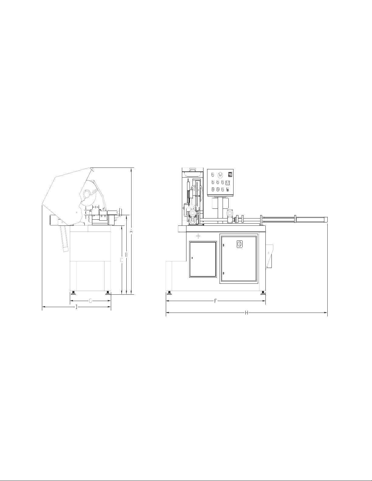
4.1 PHYSICAL DIMENSIONS
SEE FIGURE 1 ON THE FOLLOWING PAGE.
DIMENSIONS INCHES CM
A HEIGHT 65 165
B FLOOR TO VISE 38.5 98
C BASE HEIGHT 35 89
D VISE OPENING 3-5/8 9.2
E VISE DEPTH 2-1/4 5.7
F BASE WIDTH 61 155
G BASE DEPTH 25 64
H WIDTH 100 254
I DEPTH 44 112
WEIGHT 1,750 LB. 795 KG.
Page 7
FIGURE 1

Page 8
4.2 MACHINE INSTALLATION
SEE FIGURE 2 ON THE FOLLOWING PAGE.
This machine is shipped on a pallet and can be moved to the installation location by means of a forklift.
CAUTION: THIS MACHINE IS TOP HEAVY AND MUST BE MOVED WITH CARE, ON
HARD FLAT SURFACES ONLY.
USE THE FOLLOWING STEPS TO INSTALL THE MACHINE:
1. Select a location for the machine that allows adequate room for any length of material that
you may want to cut. Leave adequate space behind the machine and on either end, for set-up
and maintenance.
2. Lift the machine off of the shipping pallet, using a forklift.
3. Place the machine in its final location and level it, using the leveling pads. For this machine to
function properly, it is very important that it is level. Any supply tracks used with this machine
must also be level and aligned with the vises on the machine.
4. Install the shuttle cylinder on the machine.
NOTE: MACHINES EQUIPPED WITH A DIGITAL READOUT WILL ALREADY HAVE THE
CYLINDER INSTALLED.
5. We strongly recommend that you anchor the machine and supply tracks to the floor, with the
anchor plates provided with the machine.
6. Connect the main air and electrical supply lines to the machine. To connect the air, slide the
shuttle valve (I) down to the closed position and connect the incoming supply line. (DO NOT
TURN THE AIR ON YET.) This machine requires a minimum of 90 PSI and may require up to
130 PSI, depending on your application. The electrical supply lines must be connected by a
qualified electrician. The supply lines connect to the top of the main disconnect switch (J) located
in the lower base cabinet. Make sure that your plant phase and voltage correspond to the phase
and voltage of the machine before connecting the electrical supply.
CAUTION: DO NOT POWER THE MACHINE UNTIL THE MACHINE INSTALLATION IS
COMPLETE AND UNTIL YOU HAVE READ ALL OF THE SECTIONS OF THIS MANUAL!

Page 9
FIGURE 2

Page 10
4.3 ELECTRICAL REQUIREMENTS
CAUTION: TO PREVENT DAMAGE TO THE MACHINE AND DANGER TO THE
OPERATOR, ALL ELECTRICAL CONNECTIONS MUST BE MADE BY A QUALIFIED
ELECTRICIAN. THIS MACHINE OPERATES WITH LIQUID COOLANT AND MUST BE
GROUNDED IN ACCORDANCE WITH NATIONAL ELECTRIC CODES.
All machines are wired for three phase power. The motors are dual voltage. If the machine is not the
same voltage as your plant voltage, you will have to rewire the motor and the coolant pump.
To insure satisfactory performance, the supply voltage should be (+ or -) 10% of the motor voltage
rating. Check the motor data tag for full load current requirements. Single phase motors are not
available.
NOTE: MACHINES THAT ARE WIRED FOR 208 VOLT/3 PHASE REQUIRE AN
ADDITIONAL STEP UP TRANSFORMER. FOR ADDITIONAL INFORMATION, SEE
SECTION 11.10.
THE ELECTRICAL DIAGRAM FOR THIS MACHINE IS IN SECTION 14.0.
For supply lines ten feet (304 cm) or shorter, we recommend 12 gauge wire. For lines longer than ten
feet (304 cm), we recommend 10 gauge wire. We do not recommend supply lines over twenty feet (609
cm) in length.
CPO-315-HFA-LT (11-177 RPM)
MOTORVOLTAGE FULL LOAD CURRENT HORSEPOWER
208 22 5
230 20 5
460 10 5

Page 11
The CPO-315-HFA saw is equipped with a mist coolant system. A flood coolant system is an
option for this saw.
The container for the coolant is located on the inside of the front door of the saw.
The coolant should be mixed in a ratio of one part coolant to seven parts water. We recommend
using our P/N 075751 coolant (1 gallon) for most applications. This is also available in 5 gallon
bucket as P/N 075752 and in a 55 gallon drum as P/N 075754. This coolant can be mixed stronger
if needed.
When cutting alloy steels such as stainless steel, we recommend our special mix coolant designed
for these applications: P/N 075756 in a 1 gallon jug and P/N 075757 in 5 gallon bucket.
We recommend pre-mixing the coolant before adding it to the saw.
FOR ADDITIONAL INFORMATION ON AVAILABLE COOLANTS, SEE SECTION 12.2.
4.4 COOLANT SYSTEM
5.0 MACHINE START-UP
Before starting this machine, take the time to review the operator.s manual thoroughly, to
familiarize yourself with all of the functions of the machine.
We strongly urge you to follow OSHA directive CFR-1910.147 (effective 09-09-90) regarding
lock-out, tag-out procedures. Keep in mind that the directive refers to all hazardous energy
sources, not just electrical.
The air supply must also be disconnected and locked or tagged.
Do not install a blade on the saw until after it has been powered and cycled several times.
Once the machine has been powered, check the rotation of the spindle. There is an arrow on
the guard showing the proper rotation. If the rotation is not correct, the electrician will have
to switch two of the three line wires.

Page 12
5.1 CONTROL PANEL FUNCTIONS
The following section gives a brief description of each of the control panel switches and buttons.
Before powering the machine, please familiarize yourself with the location and the function of
each of these items. SECTION 7.0 will describe how to set the machine up for an operation.
SEE FIGURE 3 BELOW.
FIGURE 3

Page 13
5.1A MAIN POWER SWITCH
This is the main power disconnect switch for the machine and it should be locked or tagged in the OFF
position any time that maintenance or service work is being performed. Maintenance or service work on
the electrical controls must be performed by qualified personnel. This switch must be in the ON position
to operate any of the other control panel functions.
There is a red power indicator light (O) on the control panel. This light indicates that this switch is in
the ON position.
CAUTION: THIS SWITCH DOES NOT DISCONNECT THE AIR SUPPLY TO THE
MACHINE. ANY TIME THAT MAINTENANCE OR SERVICE WORK IS PERFORMED
ON THE MACHINE, THE AIR SUPPLY MUST ALSO BE DISCONNECTED AND TAGGED
OR LOCKED OUT.
5.1B MOTOR CONTROL SWITCH
This switch is used to turn the saw motor on.
5.1C POWER UP SWITCH
This switch energizes the system for the rest of the control panel functions. This switch will also
start the saw motor. The motor will not start unless the MAIN POWER switch (A) is on and the
AUTOMATIC/ MANUAL SWITCH (I) is in the manual position. The MOTOR SWITCH (B) must
be in the ON position for the saw motor to start.
5.1D EMERGENCY STOP SWITCH
This switch stops the saw motor and allows the head to return to the up position. The emergency
stop switch does not release the material vise or the air pressure. Once this switch has been used, the
operator must restart the machine in the manual position and go through the startup procedure again.
For complete instructions on changing bars of material, REFER TO SECTION 7.0.

Page 14
5.1E HEAD UP
This button is used to abort a cut in mid cycle when the AUTOMATIC/MANUAL SWITCH is in the
MANUAL position. This button is inoperable when the machine is in the AUTOMATIC position.
5.1F HEAD DOWN
This button is also used to set the overall stroke of the machine and to make manual cuts.
5.1G HITCH SELECTOR
This switch is used to select the number of hitches the shuttle vise makes before the saw makes a cut.
POSITION 1 is for parts from 0 to thirty inches in length. POSITION 2 is for parts from thirty to sixty
inches. POSITION 3 is for parts from sixty to ninety inches.
5.1H CYCLE/START BUTTON
This button starts the machine cycle. The CYCLE/START button is used to make trim cuts and set-up
cuts prior to starting the automatic operation. It is also used to start the automatic operation once all of
the test cuts are done.
5.1I AUTOMATIC/MANUAL SWITCH
This switch must be in the MANUAL position to start the machine, to make trim cuts and to set the
product lengths. After the machine has been set up and sample cuts have been made, this switch is
moved to the AUTOMATIC position. Any time that the saw is in the AUTOMATIC position, this switch
can be turned to the MANUAL position. When it is turned to the MANUAL position, the machine will
complete the cycle it’s on and stop when the head reaches the up position. The saw motor will continue to
run when this switch is used to stop the automatic operation of the machine. When this switch is in the
AUTOMATIC position and the machine runs out of product, the operator must reset the machine’s
operation. For instructions on changing bars of material, REFER TO SECTION 7.0. When this switch is
used to stop the automatic operation, you can start the automatic operation again by depressing the
TRIM/TEST SWITCH (J) and then, the CYCLE button (H). The machine will trim and cut one part.
You can then switch the AUTOMATIC/MANUAL SWITCH to the AUTOMATIC position and press
the cycle button again. The machine will continue with the automatic operation.

Page 15
5.1J TRIM/TEST
This button is used to do first part cuts prior to running the machine in the automatic position. With the
AUTO/MANUAL switch in the MANUAL position, press the TRIM/TEST button (J) and then, press
the CYCLE button (H). The saw will trim and then cut one part and return to the up position. Make
whatever adjustments that you need to and depress the CYCLE button (H) again and the saw will cut one
more test piece. After you are satisfied with all of the settings, place the AUTO/MANUAL switch (I) in
the AUTOMATIC position and press the CYCLE button again. The saw will start the automatic
operation.
5.1K COOLANT PUMP SWITCH
This switch starts the machine’s coolant pump.
5.1L VARIABLE MOTOR SPEED CONTROL
This switch is one of the most important standard features on this machine. This switch gives you a wide
range of cutting speeds. The range is from 11 RPM to 177 RPM. With this feature, you are able to match
the blade speed to the material, which greatly increases blade life and reduces vibrations. When this
switch is in the 50 percent position, the machine runs at 83 RPM. With the switch at the 0 percent
position, the RPM’S will be 11 and with the switch at the 100 percent position, the RPM’S will be 177.
5.1M COUNTER
The Parts Counter is programmed at the factory to count up. If you want to set the counter to count
down, please contact the factory. To enter a pre-set value in the counter, press any of the white keys
numbered 1 to 5. The pre-set value will appear on the screen. Use the white keys to set the total number
of pieces that you want to cut. After a three second delay, the pre-set value screen will disappear. The
counter will then display the number of pieces cut as the saw runs. When the value on the screen reaches
the pre-set value, the machine will stop. If you press the red button, the count value displayed on the
screen will be zeroed out. The reset button does not erase the pre-set value. To change the pre-set value,
press any white button and the pre-set value will appear on the screen. For the machine to run in the
automatic mode, there must be a pre-set value on the counter.

Page 16
5.1N FEED RATE CONTROL
This valve controls the down feed rate of the saw head and is used in the set-up of the up and down
stroke control of the saw head. To adjust the down feed cutting rate of the head, turn the control all the
way to the right (clockwise) and then, open it one turn. The down feed rate is set by sound. Start with a
slow rate and gradually increase it until the blade chatters, then back it off slightly. Selecting the
proper blade and the condition of the blade will effect the down cutting rate dramatically. There is also
a down feed regulator, located on the machine, that provides constant down pressure on the material.
5.1O POWER INDICATOR LIGHT
This light indicates that the main switch (A) is on and that there is power to the control panel.
6.0 MACHINE OPERATION
6.1 SELECTING THE PROPER CUTTING SPEED
In cold sawing, there is no such thing as a general purpose blade. To achieve the best results from your
saw, proper blade selection is important. Each saw is shipped with a pitch (number of teeth) calculator,
which will help to determine the proper blade for your application.
When sawing flat stock or rectangular solid sections, determine the thickest section that will be cut and
use the equivalent square size on the pitch calculator to determine the proper blade.
The CPO-315-HFA is designed to use a maximum 12-1/2 inch (315mm) diameter blade. 10-3/4 inch
blades are also available for this machine.
The chart below gives the surface feet per minute for the various spindle RPM’S:
BLADE DIAMETER SURFACE FEET PER MINUTE
INCH MM 18 88 176 RPM’S
10-3/4 275 50 247 495
12-1/2 315 59 287 576
The proper blade speed is also important. The High speed (176 RPM) is recommended for thin walled
tubes and nonferrous tubes and profiles. Some materials will require test cuts at both speeds to
determine the best speed for the application. The Low speed, 18 RPM, is recommended for solid sections
of mild steel and alloy tubes.

Page 17
THIS PAGE LEFT BLANK INTENTIONALLY.

Page 18
6.2 BLADE INSTALLATION
SEE FIGURE 4 BELOW.
FIGURE 4

Page 19
CAUTION: USE ONLY HIGH SPEED STEEL BLADES DESIGNED FOR THIS MACHINE.
DO NOT MODIFY ANY BLADE TO FIT THIS MACHINE. DO NOT USE BLADES
DESIGNED FOR THIS MACHINE ON ANY OTHER EQUIPMENT. THE MAXIMUM RPM’S
FOR THESE BLADES ARE 600 FOR THE 12-1/2" AND 700 FOR THE 10-3/4".
The CPO-315-HFA saw is designed to use a maximum 12-1/2 inch (315mm) diameter blade. The arbor
size is 40mm with four 12mm pins spaced at 65mm.
BEFORE INSTALLING THE BLADE, make sure that the power to the machine is off.
USE THE FOLLOWING STEPS TO INSTALL A BLADE:
An 8mm hex key wrench (D), shipped with each machine, is required to change blades.
1. Raise the movable hood guard to the open position.
2. Release the upper stroke control stop (H) and allow the head to travel to its full up position.
3. Back off the blade guide bolts (G), if they are being used, and slide them out to the end of the slots.
4. Remove the blade bolt (B) and the blade flange (C).
5. Check the blade flange, the blade and the saw spindle for any chips or nicks that will affect the
way the blade seats.
6. Install the blade. Make sure that the pin holes in the blade line up to the holes in the spindle.
7. Replace the blade flange (C) and start the bolt (B) into the spindle.
8. Before locking the blade in position, the back lash must be taken up. To take up the back lash,
rotate the bottom of the blade toward you until it seats against the drive pins.
CAUTION: THE BLADES ARE VERY SHARP AND CARE MUST BE TAKEN WHEN
REMOVING THE BACK LASH. DO NOT GRIP THE CUTTING EDGE OF THE BLADE
BARE HANDED. THE BACK LASH MUST BE TAKEN UP EVERY TIME A BLADE IS
CHANGED.
9. After taking up the back lash, tighten the blade bolt (B).
Table of contents
Other Scotchman Saw manuals

Scotchman
Scotchman SU-280-G User manual

Scotchman
Scotchman CPO-315-RFA-NF User manual

Scotchman
Scotchman CPO-350-NF-5HP User manual

Scotchman
Scotchman SU-280-G User manual

Scotchman
Scotchman CPO-315-HFA-NF User manual

Scotchman
Scotchman GAA-500-90 NF User manual

Scotchman
Scotchman CPO-275 User manual

Scotchman
Scotchman SU-280 User manual

Scotchman
Scotchman CPO-315-HFA-CNC User manual

Scotchman
Scotchman CPO 350 User manual


