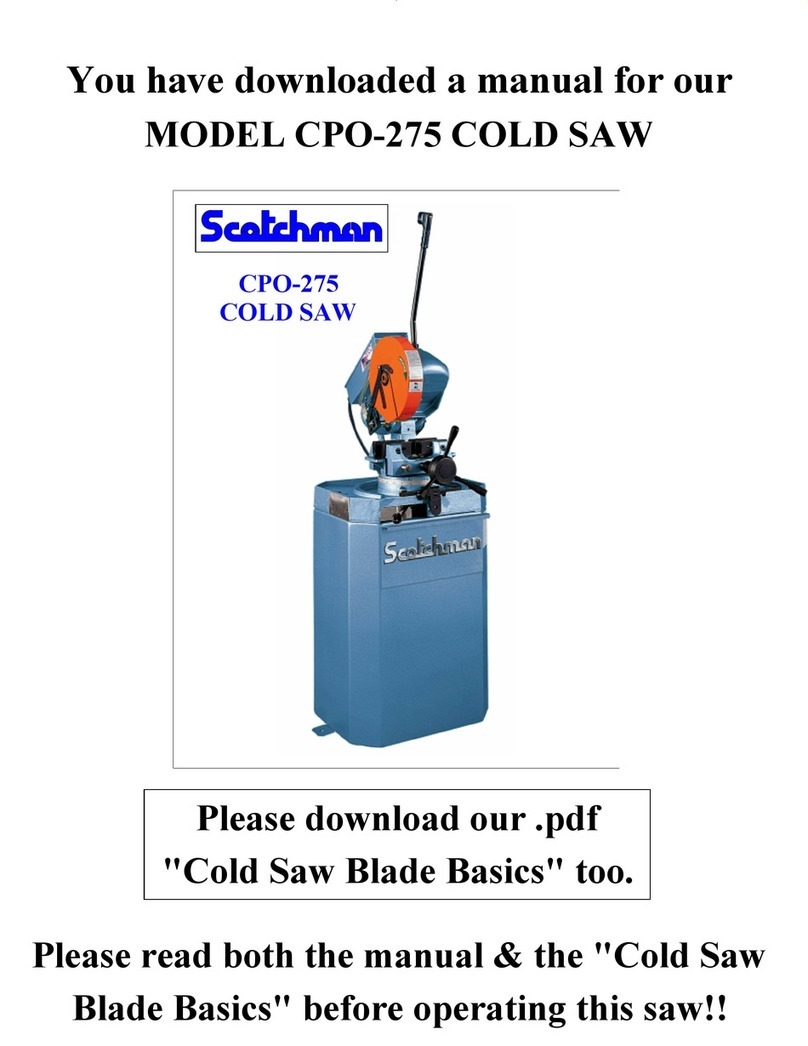
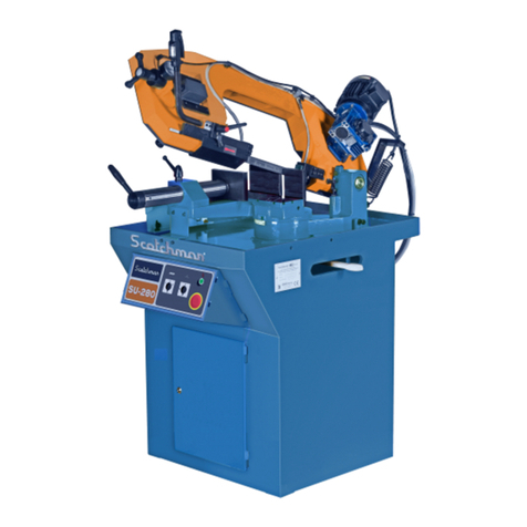
Scotchman SU-280-G User manual

MODEL
SU-280-G
BAND SAW
PRINTED APRIL 2021
SCOTCHMAN INDS. - 180 E US HWY 14 - PO BOX 850 - PHILIP, SD 57567 Call: 1-800-843-8844

Utility Band Saw
SU-280-G

WWW.SCOTCHMAN.COM
BEST
IN THE
BUSINESS
WARRANTY
S
C
O
T
C
H
M
A
N

TABLE OF CONTENTS
SECTION DESCRIPTION PAGE #
1.0 INTRODUCTION 3
1.1
GENERAL MACHINE INFORMATION 4
Safety Precautions 3
2.0
3.0
4.0
Machine Identification Data
TECHNICAL DATA
Noise level
TRANSPORT AND STORAGE
Vise Adjustment and Miter Lever
Raising and Lowering the Pivot Stop
TROUBLESHOOTING/CORRECTIVE MAINT.
GENERAL RULES & SAFETY CHECKS
Recommendations for Safety, Maintenance, & Repairs
ACCESSORIES
Material Supply Tracks
Discharge Tracks With Scales
DRAWINGS AND SCHEMATICS
7.0
9.1
9.0
4
6
5
5
5
4
4
9
8
8
8
7
6
13
13
12
11
11
3.1
2.1
5.0 ANCHORING AND SERVICE START-UP
5.1
5.2
5.3
5.4
Anchoring Instructions
Connection to the Electric System
Installing the Band Saw Blade
Selection of The Band Saw Blade
6.0 INSTRUCTIONS FOR USE
6.1
6.2
6.3
8.0
8.1
10.0
11.0
15
14
13
1.2 Warranty
Cutting Coolant5.5
3
Machine Controls
6.4 Adjustment of Cutting Blade Guides
6.5 Changing The Guide Plates
MAINTENANCE SCHEDULE
Type and Frequency of Maintenance
Electrical Schematic
17
19
21
21
23
10.1
10.2
11.1
11.2
11.3
11.4
Clamp (Exploded View)
GUIDES (Exploded View)
MACHINE EXPLODED VIEW
25
26
Page 2
SCOTCHMAN INDS. - 180 E US HWY 14 - PO BOX 850 - PHILIP, SD 57567 Call: 1-800-843-8844
10

1.0 INTRODUCTION
1.2 WARRANTY
Page 3
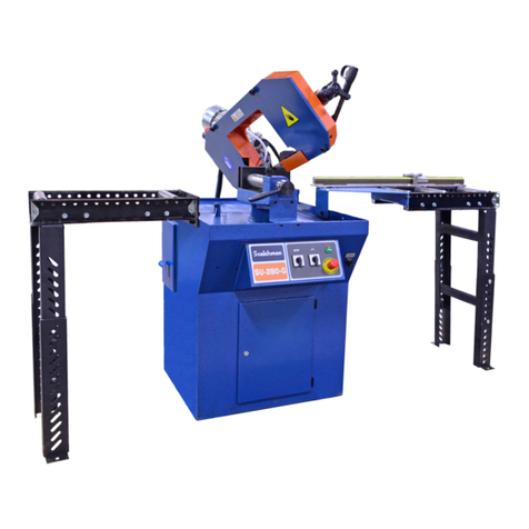
Scotchman's Utility Band Saw features a metered feed rate allowing for quick and effortless
cuts without operator assistance! The SU-280G (Gravity Feed) is a scaled-down but rugged
metal cutting band saw that combines the cutting of a traditional band saw with the flexibility
& accuracy of a cold saw. This band saw can easily cut through round material up to 8" in
diameter & features a swing head with 30 degrees (right) of mitering capability without
material movement.
1.1 SAFETY PRECAUTIONS
Scotchman Industries, Inc. will, within three years of the date of purchase, replace F.O.B. the factory
or refund the purchase price for any goods which are defective in materials or workmanship, provided
the buyer, at the seller’s option, returns the defective goods freight and delivery prepaid to the seller,
which shall be the buyer’s sole and exclusive remedy for defective goods. This warranty does not apply
to machines and/or components which have been altered, changed or modified in any way or subjected
to abuse and abnormal use, inadequate maintenance and lubrication or subjected to use beyond the
seller’s recommended capacities and specifications. In no event shall the seller be liable for labor cost
expended on such goods or consequential damages. The seller shall not be liable to the purchaser or
any other person for loss or damage directly or indirectly arising from the use of the goods or from any
other cause. No officer, employee or agent of the seller is authorized to make any oral representations
or warranty of fitness or to waive any of the foregoing terms of sale and none shall be binding on the
seller. Any electrical changes made to the standard machine due to local electrical code variation must
be paid by purchaser. As we constantly strive to improve our products, we reserve the right to make
changes without notification.
1. The operators of this machine must be qualified and well trained in the operation of the
machine. This manual is not intended to teach untrained personnel how to operate
2. All of the guards and awareness barriers must be installed on the machine and kept in good
working order.
3. Never place any part of your body into or under any of the machine’s moving parts.
4. Wear the appropriate personal protective equipment. Safety glasses are required at all
times. Steel-toed shoes and leather gloves are also recommended.
5. Always disconnect and lock out the power when performing maintenance work on the
6. Never operate this machine with a dull or damaged saw blade. Replace worn saw blades
promptly.
7. Practice good housekeeping. Keep the area around the machine clear and well lit.
8. Never modify this machine in any way without the written permission of the manufacturer.
9. Never leave this machine running unattended.
10. Set up a program of routine inspections and maintenance. Make all repairs and adjustments
in accordance with the manufacturer’s instructions.
machine.
machinery.

Page 4
2.0 GENERAL MACHINE INFORMATION
2.1 MACHINE IDENTIFICATION DATA
NOTE: In order to request replacement parts, whether they are covered by the warranty or not,
always state the model and serial number of the machine, as well as the name of the part and the
code that appear in the last chapter of exploded views.
3.0 TECHNICAL DATA
MAIN MOTOR POWER
3PH 2-SPEED 1.5 HP - SINGLE PH 1-SPEED - 1.3 HP
MOTOR SPEED SINGLE PH 1-SPEED
COOLANT PUMP POWER
CUTTING SPEED 3PH 2-SPEED
ANGLE OF CUT
BAND SAW BLADE DIMENSIONS
CUT THICKNESS
CLAMP; MAXIMUM OPENING
3.1 NOISE LEVEL
At a distance of 60cm/24"
2430mm X 27mm / 96.5" X 1-1/16"
1.5mm / .060"
290mm / 11.4"
1,500 RPM
0.09 Kw/0.12 HP
80/40 m/min - 262/131 ft/min
30° RIGHT
RUNNING WITH NO-LOAD
SAWING A 70mm x 50mm PROFILE
62 dB (A) Leq
83 dB (A) Leq
SERIAL NUMBER
YEAR OF MANUFACTURE
MODEL
MOTOR SPEED 3PH 2-SPEED 3,000/1,500 RPM
CUTTING SPEED SINGLE PH 1-SPEED 40 m/min - 131 ft/min
DIMENSIONS
WIDTH
HEIGHT
LENGTH
55"
33-1/2"
69"
WEIGHT 650 lbs.
CUTTING
CAPACITY
90°
45° RIGHT
30° RIGHT
200 - 8"
180 - 7"
100 - 4"
200 - 8"
160 - 6 1/4"
90 - 3 1/2"
280 x 180 - 11" x 7"
180 x 160 - 7" x 6 1/4"
100 x 90 - 4" x 3 1/2"
MOTOR FLA SINGLE PHASE 8.2A
MOTOR FLA 3PH 230V/460V 6.2A/2.6A

4.0 TRANSPORT & STORAGE
CAUTION: Do not improperly dispose of the packaging. Send the materials to be recycled or
eliminated in accordance with current legislation.
5.0 ANCHORING AND SERVICE START-UP
5.1 ANCHORING INSTRUCTIONS
The machine must first be checked in order to ensure that it has not suffered any damage during
transport. If so, immediately contact the manufacturer.
The machine must be installed on a firm surface that is as level as possible in order to reduce vibrations
during operation and so that it operates according to the parameters established by the manufacturer.
Page 5
A sling should be placed under the vise casting on
the front of the machine (1) and another under the
pivot casting (2) toward the rear of the machine.
The saw head should be locked in the down
position (not shown).
12
The machine is supplied in a properly designed and sized wood crate/pallet, and it is also wrapped in
plastic before it is shipped. Due to the size of the machine, it should be transported on a forklift or by a
crane bridge, using slings. If the machine is left in storage for a long period of time, lubricate
periodically. Do not expose to the elements.
In the above drawing, the machine is bolted to a
pallet before it is lifted or moved with a forklift.

5.2 CONNECTION TO THE ELECTRIC SYSTEM
Ensure that the power supply voltage corresponds to the voltage on the data plate of the machine.
Connect the cable to the electric system, using a plug that is appropriate for the
characteristics of the same, thereby respecting color codes.
After the machine has been connected, make sure that the rotation of the hydraulic motor matches
with the direction indicated by the arrow shown. If the motor rotation is not correct, swap two
of the incoming power wires and check again.
5.3 INSTALLING THE BAND SAW BLADE
In order to install the band saw blade:
Lift the frame guard and remove the blade guide guards.
Loosen the tension adjuster.
Put on the band saw blade, sending it through the interior of the guides.
Re-tighten the tension adjuster to the colored range shown on the gauge: 90-100 bar.
Put on all of the guards.
ATTENTION: When replacing the band saw blade, always use protective gloves.
DANGER: After changing the band saw blade, put on all guards again.
It is absolutely prohibited to work with them removed!!
Page 6
Turn the saw manually and use a brush to lubricate in between the two guides,
using SAE 30 lubricating oil.
ATTENTION: See the next page to help in selecting the correct blade.
NOTE : The Tension Adjuster is a
self-contained hydraulic unit. If it
won't hold pressure or if it won't
adjust properly, it is low or out of oil.
Remove pressure gauge and top off
with hydraulic oil (ISO 32).
If problem persists, inspect the unit
for leaks and remove and repair as
needed.

5.4 SELECTION OF THE BAND SAW BLADE
Page 7
TO SELECT A BLADE WITH THE PROPER TEETH PER INCH, PLEASE REFER TO THE TABLES
BELOW. THE TOP TABLE IS FOR SOLIDS AND THE BOTTOM IS FOR TUBE AND PROFILES.
TUBE SECTION
2
4
5
6
8
10
12
15
20
30
50
75
20 40 60 80 100 120 150 200 300
3-15 16
3-316
2-384-23 32 7-7811-1316
5-29 32
3
2-61 64
1-31 32
1-316
25 32
19 32
15 32
25 64
516
15 64
13 64
532
18
564
1-37 64
25 32
14 14 14 14 14 14
14 14
14 14
14
14
14
10-14 10-14 10-14 10-14
10-14 10-14
10-14 10-14
10-14 10-14
10-14 10-14
10-14
8-12
8-128-12
8-12 8-12
8-12 8-12
8-12 8-12
8-12 8-12
6-10
6-10 6-10
6-10 6-10
6-10 6-10
6-10 6-10
8-12 8-12
8-12
5-8
5-85-8
5-85-8
5-85-8
5-85-8
6-10 6-10
5-85-8
6-10 6-10
5-8
6-10 5-8
5-8
4-6
4-6 4-6
4-6 4-6
4-6 4-6 4-6
4-6 4-6
4-6 4-6
3-4
3-4
3-4
3-4 3-4
3-4
3-4
2-3
2-3 2-32-3
3-4 3-4 3-4
4-6
OUTSIDE DIAMETER OR TUBE OR MAX. PROFILE SECTION LENGTH
WALL
THICKNESS
MM INCH
L
TEETH PER INCH
3/4 - 20MM 14/14, 8/12
3/4 to 1-1/2 - 20/40MM 6/10, 6
1-1/2 to 2-3/4 - 40/70MM 6, 4/6
2-3/4 to 5-1/2 - 70/140MM 4, 3/4
5-1/2 to 7-3/4 - 140/200MM 3/4, 3
7-3/4 to 15-3/4 - 200/400MM 3, 2/3
15-3/4 - 400MM 1/2, 1.25
L (INCH - MM)
DIMENSIONS ARE SHOWN AS INCH - MM

Page 8
5.5 CUTTING COOLANT
CAUTION: When it is necessary to empty the liquid coolant tank, please properly dispose of the
old coolant.
ATTENTION: The use of any other kinds of coolants may cause irreparable damage to the machine,
as well as diminish the quality of the cut and reduce the life of the saw.
6.0 INSTRUCTIONS FOR USE
6.1 VISE ADJUSTMENT AND MITER LEVER
Use only pure, synthetic water-soluble sawing coolant in this saw. The saw holds 4 gallons. Coolant
should be mixed in a ratio of one part coolant to seven parts water. Premixing the coolant before
adding to the saw is also recommended. Add through the top of the saw. DO NOT OVER FILL!!
1
2
3
1. The vise is opened and
closed using lever #1.
Use lever #2 to adjust
the vise jaws to less
than 1/4 inch (6mm)
from the material
being clamped.
2. Use lever #3 to adjust
the angle of the cut.
Move the lever toward
the rear of the
machine to loosen.
Now the blade angle
can be changed.
Move lever toward the
front of the machine to
lock the blade in place.

6.2 MACHINE CONTROLS
START
BUTTON
COOLANT
SWITCH
SAW BLADE SWITCH
3-PHASE SAWS HAVE 2 SPEEDS.
SINGLE PHASE SAW HAS 1 SPEED.
HANDLE
& SWITCH
FLOW
CONTROL
FLOW CONTROL IS LOCATED TO THE
RIGHT OF THE CONTROL PANEL AND
CONTROLS THE SAWS DESCENT SPEED.
THE CONTROL PANEL IS LOCATED ON THE FRONT OF THE MACHINE.
THE SWITCH ON THE HANDLE STARTS
THE SAW BLADE.
EMERGENCY
STOP BUTTON
Page 9

Page 10
6.3 RAISING AND LOWERING THE PIVOT STOP
IMPORTANT: Always make sure the material is clamped securely in the vise jaws.
1
2
3
The electric switch (1) is activated when the moving cylindrical stop (2) contacts it. The cylindrical stop
should contact the switch first and turn off the saw. The cylindrical stop should then rest on top of the
adjustable hard stop (3) that completely stops the downward travel of the saw. The saw head will stay in
this position until the operator manually returns the head to the up position.
When adjusted correctly, the saw should stop when the blade is just below the surface of the saw bed.
Check this to make sure it is set correctly. This is set at the factory and shouldn't need to be adjusted.
WARNING: When the saw is cutting, it is important that the saw is fed into the material at a
constant rate, with no sharp changes of down pressure. If the saw becomes jammed in the material,
release the rotation control and raise the head.

Page 11
6.4 ADJUSTMENT OF CUTTING BLADE GUIDES
6.5 CHANGING THE GUIDE PLATES
FRONT GUIDE REAR GUIDE
3
4
6
1
9
8
In order to obtain a square cut, you must make sure that there is a distance of .035 thousandths of an
inch (0.9 mm) between the side guide plates (2), so that they are all in contact with the blade. To
adjust this distance the blade must be removed. The exploded view below the front and rear image is
to show all of the parts and their locations. Follow the instructions given below:
1. Remove the nylon blade protector (1). It is
held in place with a small bolt and washer.
2. Use a feeler gauge and check between the
side guide plates (2) to see what the
clearance is. The clearance should match
the the blade thickness. 35 thousandths of
an inch (.035") is the most common size for
this machine.
3. To adjust the clearance, use the two set
screws (3). The gauge must slide smoothly
but without wobbling. If a gauge is not
available, a piece of the old blade may be
used. The mounting bolts (4) may also need
to be slightly loosened and re-tightened.
4. The upper guide plate (5) should have 4
thousandths of an inch (.004") clearance
2
1
3
Note that only the right side guide plate is adjustable.
Only the rear guide is shown in the exploded view but
the front guide is adjusted the same way.
between it and the top of blade. Too much pressure can cause the top of the blade to mushroom
and become wider. To prevent this, the whole guide assembly can be adjusted with two bolts (6)
as the holes are slotted for adjustment.
5. The rear guide support (7) can also be adjusted via the mounting bolts (8) and set screws (9).
This is set at the factory and normally does not need adjusting.
6
7
8
9
7
4
5
SLOTTED
HOLES
Over time, the side plates (2) and the upper plate (5) may need to be replaced.
To do so, follow the steps below:
1. Loosen the screws (4) on both sides of the guide and remove the guide plates.
2. Tap the upper plate (5) through the hole on top until it comes out of its housing.
3. Fit the upper plate (5) up into the housing and then the side plates (2).
4. Adjust the lateral clearance of the plates, as explained in the previous section,
ADJUSTMENT OF CUTTING BLADE GUIDES.
Also see
SECT. 11.4 GUIDES
(EXPLODED VIEW)
for more detailed
information

Page 12
7.0 TROUBLESHOOTING/CORRECTIVE MAINTENANCE
PROBLEM POSSIBLE CAUSES
The machine does not start.
Motor fuse has blown.
2A fuse has blown. (located inside the Control Panel)
The rear arc guard has not activated the safety
micro-switch, or this is not working properly.
Check the operating contactor, start-up control and
Tension too low or too high. See Section 5.3
Condition of the saw blade.
Coolant liquid used. We recommend pure,
synthetic coolant mixed 7 to 1 with water.
Condition of the blade guide plates.
Guide adjustment. See Section 6.4
Excessive wear on blade.
Tension too low or too high. See Section 5.3
Guide plates worn.
Excessive pressure from upper plate. See Section 6.4
Feed Rate is too high or batch cutting.
Quality or pitch of blade unsuitable
for the material or section to be cut.
Coolant liquid used. We recommend
pure, synthetic coolant mixed 7 to 1.
Noises when saw rotates.
State of blade guides. See Section 6.5
Excessive tension on the saw blade.
(4) Bearings # 57 Section 11.2
State of the cutting blade.
Remove pressure gauge and top off with
hydraulic oil (ISO 32).
Check for oil leaks, state of internal flanges,
tensing mechanism, flywheel and bearing.
Check the incoming power supply.
Bad quality or out-of-square cut.
The pressure gauge does
not reach 100 bar.
transformer. (Above located inside the Control Panel)

8.0 MAINTENANCE SCHEDULE
8.1 TYPE & FREQUENCY OF MAINTAINENCE
LUBRICATION POINTS
Pivot Pin Sect. 11.2 #16
Front and Rear Blade Guides
Bearings Sect. 11.2
CHECK
Saw blade tension
Level of coolant liquid
Cleanliness of machine
Cleanliness of coolant tank
Saw blade guides
TYPE OF GREASE/OIL
Bearing grease
SAE 30
Bearing grease
MATERIALS TO USE
90-100 BAR (see gauge)
Top up with WHITE COOLANT
Diluted mild degreasing fluid
Damp cloth, brush
Replace, if necessary
Sections 6.5 & 11.4
FREQUENCY
Yearly
Weekly
Weekly
FREQUENCY
Daily
Daily
Weekly
Monthly
Monthly
Monthly
9.0 GENERAL RULES & SAFETY CHECKS
Page 13
Before using the machine, check the effectiveness and perfect operation of the safety devices. Check
that the moving parts of the machine are not blocked, that there are no damaged parts and that all of the
machine components are positioned correctly and that they work properly.
Verify that the motor-guard switch works correctly by testing it during a no-load cycle of the machine.
It is absolutely prohibited to alter any safety device.
It is absolutely prohibited to work without the guards in place.
It is mandatory to use gloves when changing the saw blade.
Always use appropriate PPE (Personal Protective Equipment).
Before starting work, the operator must be sure to remove all tools and wrenches that have been used
for any maintenance or adjustments.
In the event of fire, use powder extinguishers and disconnect the machine from the electric system.
Condition of nylon
shaving guard Sect. 11.4
►
►
►
►
►
►
►
►

Page 14
9.1 RECOMMENDATIONS FOR SAFETY,
MAINTENANCE, & REPAIRS
Repairs shall be made exclusively by qualified personnel; using original replacement parts. If not,
the machine may be damaged and the user may be injured.
Maintenance and cleaning of the machine must be performed regularly. The life of the machine and
its optimal operation depend on it.
If the machine is broken down or the saw blade must be replaced, a lock must be placed on the
protection switch and the keys must be placed under the care of qualified personnel.
Before performing any repairs on electrical devices, disconnect the plug from the power supply.
In the event that extension cords are used, ensure that the cable used has the appropriate gauge for
the machine's power.
Whenever any part has to be replaced, use an original replacement part and, if applicable, use the
oil recommended by the manufacturer.
NOTE: In case of any doubt or problem, please call us at the number below.
SCOTCHMAN IND. Call: 1-800-843-8844
ATTENTION: The manufacturer hereby guarantees the supply of each one of the parts or
components for at least three years from the manufacturing date of the machine.
SU-280-G Band Saw
NOTE: THERE IS A STORAGE
AREA IN THE BASE OF THE
SAW. THE DOOR LATCH
DOES NOT LOCK AND CAN
BE OPENED WITH A
SCREWDRIVER OR A COIN.
►
►
►
►
►

10.0 ACCESSORIES
Scotchman has several accessories to help with your sawing needs; the first of which are our Material
Supply Tracks. They are available in 5' and 10' lengths and can be assembled to as long as needed.
The same is true for our Discharge Tracks. They are available with either our Quick-Loc or Multi-Loc
measuring systems, which will save you time and increase your productivity.
The Quick-Loc can be changed quickly from one length to another. It has a 10" extension arm that can
be used to cut short lengths closer to the blade. The whole stop assembly can be flipped up, out of the
way, if needed.
The Multi-Loc can be set up to cut several lengths from one bar of material. These simple and efficient
measuring systems can be used in many applications: drilling - tapping - punching - shearing, as well as
sawing. These tracks and measuring systems can also be purchased in either Left or Right hand
configuration. Please visit Scotchman.com to see a demonstration of how well our measuring systems
work. We think you'll be impressed!
130110
111000
130110
111000
130208
130208
130208
130208
29241.1
201205
M10x16
201205
M10x16
201205
M10x16
201205
M10x16
130208
130208
130208
130208
29175
29241.1
201205
M10x16
201205
M10x16
201205
M10x16
201205
M10x16
029220
029220
029220
029220
029220
029220
029220
29201
29219
141517
133313
29210
29232 Assy
R
029220
029220
29298
29298
MULTI-LOC
VERTICAL STOP
130208
201205
M10x16
29219
141517
133313
29210
29232 Assy
R
029220
QUICK-LOC
Page 15
Scan QR Code
To See Multi-Loc
System In Use!!
See Sect. 10.2 for more info on
Discharge Tracks With Scales
See Sect. 10.1 for more info
on Material Supply Tracks

Page 16
This Digital Quick Stop is an entry level
programmable stop and is available in 8'
and 12' lengths. It is priced right, yet
very durable. Setup is as easy as entering
the desired cut length and pressing go!
SCOTCHMAN RG DIGITAL QUICK STOP
The RG Stop/Pusher System can be used as
a "go to" stop or as a semi-automatic push
feed system. It uses Windows-based
technology with touch screen controls.
The system feeds from left to
right only. Available in lengths
from 8' to 30'. The Stop/Pusher
system can be paired with the
punch stations of the
Scotchman Ironworkers and
Scotchman Cold Saws.
SCOTCHMAN RG STOP/PUSHER SYSTEM
Scan QR Code
to see Digital
Quick Stop
video!!
Scan QR Code
to see RG
Stop/Pusher
video!!
CALL TOLL FREE
1-800-843-8844
email:
WEBSITE
www.scotchman.com
SHOWN WITH
OUR COLD SAW.
QUICK STOP IS
AVAILABLE FOR
THE SU-280-G.
SHOWN WITH
OUR COLD SAW.
THE STOP/PUSHER
SYSTEM IS
AVAILABLE FOR
THE SU-280-G.

Page 17
10.1 MATERIAL SUPPLY TRACKS
A 10’ and 20’ roller supply track is an available option for this saw. They can be bolted to the input side
of the saw (either the left or right hand side) to support longer pieces of material. If a longer supply track
is needed, these can be bolted together, end to end. The ten foot supply track shown here bolts to the left
side of the machine, to the base casting.
SEE THE DRAWING ON THE FOLLOWING PAGE.
1. Attach the Conveyor Connector to the left side of the base casting of the saw, as shown on the next
page. The Right-Side version has a different Support Bracket, but everything else is the same.
2. Bolt the Upper Leg to the Conveyor. The easiest way is to lay the Conveyor on the floor, top-side
down, and bolt the Upper Leg on. See the Upper parts group. The Upper Leg can be positioned
anywhere along the Conveyor, but further from the saw is better.
3. Measure from the floor up to the Top of the Conveyor Connector.
4. Bolt the Lower Leg to the Upper Leg, using this measurement. With the Conveyor still top-side
down, measure up from the floor to the bottom of the Lower Leg - where it will contact the floor -
and bolt the Lower Leg on. Final adjustment is done when it is attached to the saw.
5. With the Conveyor/Leg Assembly right-side up, bolt it to the saw via the Conveyor Connector, as
shown on the next page. End Brackets may have to be mounted on the Conveyor as shown, first.
6. Adjust the Leg so that the Conveyor is Level and Square to the saw. Make sure that the rollers on
the Conveyor are the same height as the Saw Bed. Adjust where needed.
7. The Legs may be anchored to the floor, using the mounting bolts provided.

Page 18
2
3
1
End-Brackets
29241 5' ROLLER CONVEYOR
5/16 Nut
5/16 Nut
5/16 x 3/4
5/16 x 3/4
(2) - 5/16 in. Star
Washer Nuts
(2) - 5/16
Carriage Bolts
DESCRIPTION
PART NUMBER
QTY
ITEM
UPPER LEG
29244.2
11
LOWER LEG029244.1
2
2
M10x25 DIN933 HHCS
203210
8
3
16
4
8
5
M10 DIN125 FLAT WASHER
214012
M10 DIN 934 HEX NUT
208012
029244 LEG-ROLLER CONVEYOR
028682 REPAC BOX SU-280 LS
DESCRIPTION
PART NUMBER
QTY
ITEM
CONVEYOR CONNECTOR
028636
11
M10x25 DIN933 HHCS
203210
6
2
M10 DIN125 FLAT WASHER
214012
6
3
M10 DIN 934 HEX NUT
208012
6
4
2
34
3
5
2
4
3
1
5
4
4
4
029987 10' SAW CONVEYOR W/LEGS SU-280
DESCRIPTION
PART NUMBER
QTY
ITEM
10' ROLLER CONVEYOR
029243
11
LEG- ROLLER CONVEYOR029244
1
2
REPAC BOX SU-280 LS
028682
1
3
4
3
2
3
14
2
P/N 029987 - 10' Saw Conv. W/Legs SU-280 LS
P/N 029988 - 20' Saw Conv. W/Legs SU-280 LS
P/N 029989 - 10' Saw Conv. W/Legs SU-280 RS
P/N 029995 - 20' Saw Conv. W/Legs SU-280 RS
29243 10' ROLLER CONVEYOR
Other manuals for SU-280-G
1
Table of contents
Other Scotchman Saw manuals

Scotchman
Scotchman CPO-315-RFA-NF User manual

Scotchman
Scotchman GAA-500-90 NF User manual

Scotchman
Scotchman SUP-600-NF User manual

Scotchman
Scotchman CPO-350-NF-5HP User manual

Scotchman
Scotchman CPO-275 User manual

Scotchman
Scotchman CPO-315-HFA-NF User manual

Scotchman
Scotchman SU-280-G User manual

Scotchman
Scotchman SU-280 User manual

Scotchman
Scotchman CPO-315-HFA-5HP User manual

Scotchman
Scotchman CPO-315-HFA-CNC User manual