Scraper Systems FleetPlow 440T Portable User manual

1
Effective: March 1st 2018
OWNER’S MANUAL
FleetPlow™FOR Trucks
Model 440T & 440S Portable Model 110T & 110S Base-Mount
OneTAP™ Full Automation or AutoUP™ Standard Automation
For your records, please record these serial numbers, found on the inside of the control panel door:
FleetPlow Serial Number:
Control System Serial Number:
WARNING: This machinery should not be operated or maintained by any person who has not read and understood all
the contents of this manual. Installation and service should be performed by an authorized dealer. Failure to read and
comply with the contents of this manual can result in serious bodily injury or death, and/or property damage.

2
Table of Contents
Manufacturer’s Warranty, page 2
Operating Information and Requirements, pages 2-3
Conversion for Rolling (Portable Models Only), page 4
Operating Procedure for OneTAP™ Full Automation,page 4
Operating Procedure for Standard Automation with AutoUP™, page 4
Operating Procedure for Manual Operation (using pendant control), pages 5-6
Multi-Trailer Operation, page 6
Maintenance, pages 7-8
Troubleshooting, pages 8-11
OneTAP Load Spring Piston Proximity Sensor Installation, page 11
Drawings, pages 12-16
Parts Lists, pages 17-19
North American Warranty
Scraper Systems FleetPlows™ are warranted, from the date of shipment, to be free from defects in material and workmanship for a
period of two (2) years on all mechanical and electrical parts and one (1) year for labor, based on approved travel and labor repair times.
The FleetPlow must be used in accordance with manufacturer’s recommendations and must not have been subject to abuse, lack of
maintenance, misuse, negligence, or unauthorized repairs or alterations. The FleetPlow must have been installed by certified dealer
installers or by factory installers, with training on the safe and proper operation provided by same.
NOTICE: FleetPlows are designed for safe and effective snow clearing in controlled commercial applications. Like with all large machines,
care must be taken by all personnel in the vicinity to uphold common sense safety practices and operate the machine only as it is
intended. Failure to do so may result in damage to this or other equipment and/or personal injury or death.
Key Tips for Optimal FleetPlow™ Performance
1. LEVEL TRAILER. Minimize any slope, front to back or back to front.
2. CENTER THE TRAILER by aligning vehicle with the V-point of the plow.
3. MINIMIZE CHAIN SLACK to 2 links or less when plow is resting on roof. (OneTAP automation is pre-programmed.)
4. REMOVE GROUND SNOW as necessary. Avoid snow build-up beneath the FleetPlow.
5. ACCELERATE TO 8-10 MPH while passing under the plow, clearing the snow off the vehicle roof.

3
Important Information
Electrical Service Required: 120 volt, single phase, 15 amps.
Electric Sources:Suitable extension cord; small portable generator, minimum 1400 Watt continuous run; or hard wiring for stationary applications.
Snow Depth Capacity: Up to 24” of wet snow; deeper amounts may require a second pass.
Storage of Plow Assembly When Not In Use: Store the plow in the full up position with the front bottom plow assembly guide wheels above the
reflective tape strips.
Off Season Storage:The plow assembly should be bolted to the columns in the full up position using the provided summer storage bolts (see figure 1,
pg.16). Once secured, relieve tension in the hoist’s load chain by leaving approximately 2 links of slack in the chain.
Basic Operating Requirements (All Models)
•Refer to the provided hoist Owner’s Manual for maintenance and safe operation of the hoist.
•Safety Stops (#01580) on columns must remain in place at all times.
•Always ensure no people are underneath the plow, or anywhere in the drive-thru area. People must stay clear of
discharging snow and ice.
•Plow assembly must always be in the maximum up position with bottom plow assembly guide wheels above the
reflective tape strips located on the columns, before entering the scraper area.
•Always enter the FleetPlow at a slow, safe speed – 5 MPH maximum.
•Always align the vehicle center with the V-point of the plow and stop the vehicle once the point of plow is extending over the leading edge of
the trailer a minimum of 12”.
•Before driving forward, always ensure that the plow assembly is on top of the trailer and not hanging in front of the
leading edge of the trailer.
•Once plow assembly has been lowered, as specified in the Operating Procedures, always remove any excessive slack in the chain before
driving forward.
•Never back the trailer up while the plow assembly is on the trailer.
•Drive vehicle forward at a steady speed, accelerating to 8-10 MPH.
•Never allow a mound of snow to build up in the drive-thru. Remove built up snow as necessary, only when the plow assembly is in the full up
position.
•Do not use the FleetPlow for anything other than removing snow and ice from vehicle roof tops. The machine is not
designed for and must not be used for lifting, supporting, transporting people or for lifting or supporting loads over people.
•Do not operate a damaged or malfunctioning FleetPlow. Call Scraper Systems or your dealer for service.
•Always turn off power to unit when not in use.
•Do not use the OneTAP automated feature of your FleetPlow to clear snow off roofs when pulling a set of multiple trailers. See Multi-Trailer
Operation instructions.

4
Conversion Between Operating and Rolling Modes (Portable FleetPlows™ Only)
1) To prepare for rolling, fasten the provided tow bar angles (P/N 41580) to the front and back of the unit in the holes provided at each wheel set
frame.
2) Remove concrete ballasts with forklift.
3) Using the screw jacks, lower each wheel set so the FleetPlow frame is raised approximately 2 inches off the ground.
4) Attach suitable towing chain or strap to the hole provided on the front tow angle at the swivel wheel front end.
5) Tow slowly to the desired location on your lot and position.
6) To prepare for operation, use jacks to raise each wheel set so the frame is lowered onto the ground.
7) Place the concrete ballasts on the integrated steel pads on each side.
8) Remove the tow bar angles and store on the provided storage hooks.
Operating Procedures
for Models Equipped with Full Automation - OneTAP™
1) Turn Selector Switch to Auto, if plow is not in full up position, press the OneTAP button to raise plow to up position.
2) Green Blinking LED Traffic Light Indicates: Plow assembly is in the full up position, so driver may enter the
FleetPlow. Plow is stationary. Driver should always check that the bottom wheels of the plow assembly are above
the reflective tape strips on the columns.
3) Driver enters FleetPlow. Vehicle must be centered in the drive-thru, aligned with the v-point of the plow.
4) Blue LED Spot Light (Always ON):Driver stops when Trailer Locator Blue Beam shines on front left corner of trailer, as viewed in side-view
mirror.
5) Driver exits the cab and taps the lit green OneTAP start button, conveniently located at the Start Station.
6) Red Blinking LED Traffic Light (and now red OneTAP button) Indicates: Plow assembly is now automatically lowering to the trailer top. Do
not move vehicle.
7) Driver waits and observes plow assembly lowering onto trailer top to confirm correct positioning of trailer with the Blue Spot Light. Plow
point will be approximately 12” onto the trailer.
8) Green Blinking LED Traffic Light (and now green OneTAP button) Indicates: Plow has stopped and is in proper position for snow clearing
operation.
9) Driver returns to cab and drives forward, accelerating to a speed of 8-10 MPH, to clear the snow from the roof.
10) Red Blinking LED Traffic Light (and now red OneTAP button) Indicates: Plow assembly is rising to full up starting position for next vehicle.
Plow is in motion.
11) Green Blinking LED Traffic Light (and now green OneTAP button) Indicates: Full up sensor has detected the plow assembly, stopping its
rise. The next driver may now enter the FleetPlow.
NOTE: A back-up pendant controller is provided for manual operation for unique circumstances or in the event there is a temporary malfunction of
the OneTAP full automation module. Use of the back-up pendant control will immediately override the automated system. The back-up manual pendant
controller is stored in the box mounted on the start station.

5
Operating Procedures
for Models Equipped with Standard Automation - AutoUP™
1) Turn selector switch on main control box to Auto.
2) Driver should always check that bottom wheels of the plow assembly are above the reflective tape strips located on the columns before
entering the FleetPlow.
3) Driver enters FleetPlow area, centering on the v-point of the
plow assembly and stops the truck so that plow assembly
extends over the top of the trailer a minimum of 14”. Trailer is
now blocking the signal between the opposed photoelectric
sensors mounted on each column.
4) Using the pendant control down button, lower the plow
assembly to the surface of the roof top with the weight of
plow lightly resting on the trailer. Release the down button on
the pendant to stop the hoist after approximately 2 links or
less of slack has gathered. Jog the up button on the pendant
to reduce any excessive slack before proceeding.
5) Driver drives forward, accelerating to a speed of 8 to 10
MPH,to clear the snow off the roof.
6) As trailer exits the FleetPlow, the sensor signal is no longer blocked and the plow assembly will automatically rise to the full up position,
stopping when detected by the plow full-up sensor.
7) The next driver may enter the FleetPlow once the plow assembly has risen above the reflective tape strips and has stopped moving.
Operating Procedures
for Manual Operation: (using back-up pendant control)
1) When necessary, turn selector switch to Manual
2) Driver should always check that the bottom wheels of the plow assembly are above the reflective tape strips located on the columns before
entering the FleetPlow.
3) Driver enters FleetPlow area, centering on the v-point of the plow assembly and stops the truck so that plow assembly extends over the top
of the trailer a minimum of 12”.
4) Using the pendant control down button. Lower the plow assembly to the surface of the roof top with weight of plow lightly resting on the
trailer. Release the down button on the pendant to stop the hoist after approximately 2 links or less of slack has gathered. Jog the up button
on the pendant to reduce any excessive slack before proceeding.
5) Driver drives forward, accelerating to a speed of 8 to 10 MPH,to clear the snow off the roof. CAUTION: Before leaving the FleetPlow area,
the driver or operator must raise the plow assembly to full up position for the next driver.

6
6) Using the pendant control up button, raise the plow assembly until the full up sensor detects the plow assembly, automatically stopping it.
Release up button.
7) The next driver may now enter the FleetPlow.
Multi-Trailer Operation (Doubles or Triples) never use the Automation features for multi-trailer operation.
In deeper, wetter, snow conditions, cleared snow and ice falling between coupled trailers may cause damage to air lines. In these
conditions, de-couple the trailers and pull the trailers through individually.
NOTE: It is recommended to provide an operator to raise and lower the plow assembly with the pendant control and to signal the driver when to start
and stop.
1) Driver should always check that the bottom wheels of the plow assembly are above the reflective tape strips located on the columns before
entering the FleetPlow.
2) Driver enters FleetPlow area, centering on the v-point of the plow assembly and stops the truck so that plow assembly extends over the top
of the first trailer a minimum of 12”.
3) Using the pendant control down button, lower the plow assembly to the surface of the roof top with the weight of the plow lightly resting on
the trailer. Release the down button on the pendant to stop the hoist after approximately 1-½ to 2 links of slack have gathered. Jog the up
button on the pendant to reduce any excessive slack before proceeding.
4) Driver drives forward steadily to clear the snow off the roof.
5) Driver stops when plow comes off back of first trailer.
6) Using the pendant control up button, the operator must raise the plow assembly to a height that allows the driver to safely pull forward and
position the next trailer accordingly.
7) Once the next trailer is positioned, repeat step 3 above.
8) Repeat Step 4 above.
9) Repeat process for additional coupled trailers.
10) Using the pendant control up button, raise the plow assembly until the full up sensor detects the plow assembly, automatically stopping it.
Release up button.
11) The next driver may now enter the FleetPlow.

7
Maintenance
**Please contact one of our North American network of dealers to provide an efficient preventative maintenance program for your FleetPlow™.**
All Models Criteria Action
Test the Operation of the Unit
Verify electrical system is functioning properly.
Test run unit several times in the fall before
the first snow.
8” Plow Guide Wheels and
Bearings
Guide wheels should be free of cracks or breaks and
rubber tires should not have excessive wear or flat spots.
Wheels should turn freely on axle.
Clean and grease once a year or replace as
neccessary.
8” Plow Guide Wheel Axles and
Pins
Axles to be visually straight.
Replace pins, shafts or brackets if bent.
Rubber Plow Squeegee
Visually check that rubber plow squeegee is free of tearing
or excessive wear.
Replace as neccessary.
Electrical Components
Visually inspect electrical boxes, cordsets, cables and
connectors for loose connections or damage.
Tighten or replace as neccessary.
Bolts, nuts, and other fasteners
Bolts, nuts, and other fasteners should not be loose.
Tighten or replace as neccessary.
Lifting hook and eye
Visually check that hoist’s lifting hook is securely hooked
to the plow’s lifting eye.
Secure if neccessary.
Pendant - Housing
Pendant housing should be free of cracks and mating
surfaces of parts should seal without gaps.
Replace.
Pendant - Wiring
Wire connections to contacts in pendant should not be
loose or damaged.
Tighen or repair.
Portable Model (Only) Criteria Action
12” Base Wheels and Bearings
Base wheels should be free of cracks and breaks. Wheel
should turn freely on axles.
Grease once a year or replace as
neccessary.
Jacks
Jacks should crank up and down easily.
Only try to lift unit when ballasts are removed.
Grease once a year or replace as
neccessary.
** Criteria and Actions listed below are brief excerpts from the hoist manual. Always refer to the full hoist Owners Manual (provided) for full
explanation and requirements of hoist inspection procedures, frequency, criteria, and action.**
Electric Chain Hoist Criteria Action
Hoist Load Chain Lubrication
Entire surface of each chain link should be coated with
lubricant and should be free of dirt and grime.
An auditory
indication that lubrication is neccessary is when chain
emits a cracking noise when hoisting a load.
Clean and Lubricate.
(see Section 6.0 in Hoist Manual)
(see Figure 6.2 in Hoist Manual)
Load Chain Surface Conditions
Should be free of rust, nicks, gouges, dent and weld
splatter. Links should not be deformed and show no sign of
significant wear. Surfaces where links bear against one
another should show no sign of significant wear.
Replace.

8
Electric Chain Hoist Criteria Action
Hook – Hook Latches
Latch should not be deformed. Attachment of latch to
hook should not be loose and Latch spring should not be
missing or weak. Latch, when depressed and released
should snap smartly into closed position
Replace.
Hook – Swivel Bearing
Hooks swivel bearing should rotate freely with no
roughness. Bearing parts and surface should show no
signs of significant wear.
Clean/lubricate or replace as required.
Contactors
(see hoist manual)
Visually check if contacts have burnt marks which may
cause intermittent movement.
Good - Spray with Corrosion X.
Intermittent - Replace contacts.
(requires removal of hoist cover)
Gear Box Oil Level
(see hoist manual)
Oil level can be checked using the check hole on the side
of the hoist body.
Refer to hoist manual for warnings and criteria for
checking hoist gear oil levels.
(requires removal of hoist cover)
Troubleshooting
Always check that cable and cordset connectors are properly connected and tightened at junction and control boxes. Connectors should only be hand
tight for a proper seal. Over tightening using pliers or vise grips may damage seals.
Situation – All Models Action(s)
No power
Turn disconnect switch on.
Check that circuit breakers are not turned off or tripped. (Breaker that show Red are on, Breakers tripped if
green)
Check for required electrical service at main control enclosure is 120V.
If using an extension cord, check that the cord is plugged into the receptacle.
Ensure extension cord is functioning properly and providing 110V to control box.
General Malfunction First raise the plow to full up position using the pendant controller. Then reset system by turning
power off and back on. If the malfunction continues, use of the manual pendant control may be
necessary until service can be arranged by your dealer.
Pushing pendant buttons does not raise or
lower plow.
Check that pendant connection is properly plugged/tightened to receptacle.
Check that Ice has not formed around buttons.
With pendant removed from all power sources, remove back cover of pendant and check that wires
are tightened properly, not loose, broken or corroded.
Check for loose wire(s) in main enclosure and junction box.
Refer to Hoist Manual for trouble shooting hoist.
LED Flood light doesn’t come on
(No photo control supplied on LED floodlight
November 2017 to present)
Check that connection is properly plugged and/or tightened into the receptacle on the junction box.
Check for loose wire connection in light and/or junction box.
Light stays on all the time. (for unit prior to
November 2017)
Check that the photo cell is not covered by debris or another object.
Check photo cell for loose and/or corroded connections.
Plow does not clear snow towards back of
the trailer. Plow not in contact with roof’s
entire length.
Level trailer to reduce slope if front higher than back.
Ensure drive-thru is clear of built-up mounds of snow, particularly where the back wheels of the
tractor will come to rest when properly locating the plow assembly over the trailer.
Slope of the exiting path is excessively inclined. Manually increasing the amount of slack with
another link of chain may resolve this. Or relocate the FleetPlow to a more level location.
Plow seems to drop hard off back of
trailer.
Level trailer to reduce slope if back higher than front.
Ensure drive-thru is clear of built-up mounds of snow.
Slope of the exiting path is excessively declined. Manually decreasing the amount of slack by
another link may resolve this. Or relocate the FleetPlow to a level location.
Excessive solid snow or ice build-up on the roof can create a ramp effect at the back of the trailer.

9
Situation - Standard Automation, AutoUP Action(s)
Plow doesn’t raise automatically.
Selector Switch is in the manual position.
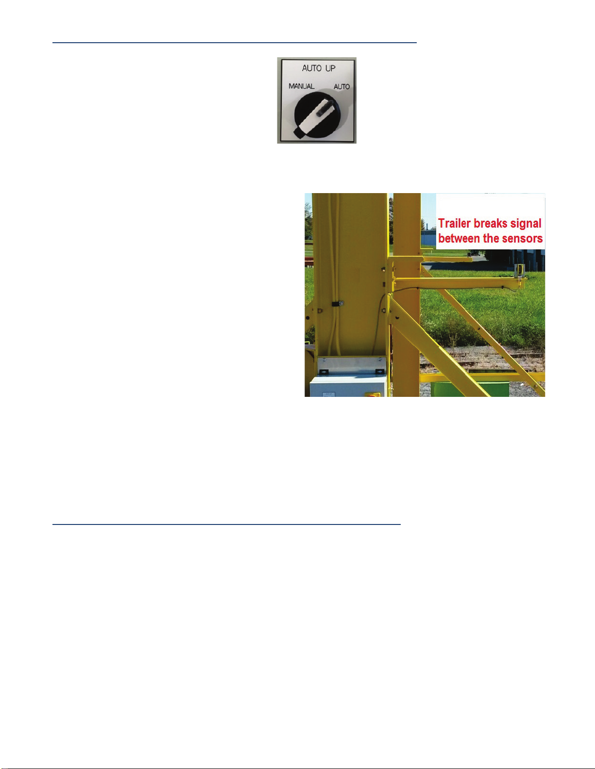
Emitter and Receiver sensors not lined up.
(
LED on top of Receiver should be off when lined up correctly.)
Emitter and Receiver sensors are installed on the wrong sides.
Plow Full Up sensor cable switched with Emitter cable on junction box.
Plow doesn’t stay down in Auto mode.
No Truck in sensor area.
Emitter and Receiver sensors are installed on the wrong sides.
Cables for the Emitter and Plow Full Up sensor are switched at junction box.
Plow doesn’t stop at full up sensor while
raising.
Cable not tightened properly on back of sensor or junction box.
Plow Full Up and Emitter cables switched at junction box.
Plow Full Up Sensor and/or cable broken.
Plow does not clear snow towards back of
the trailer. Plow not in contact with roof’s
entire length.
The front of the trailer is higher than the back. Level trailer to reduce slope.
Ensure drive-thru is clear of built-up mounds of snow.
If slope of the exiting path is excessively inclined, manually increasing the amount of slack with
another link may resolve this. Or relocate the FleetPlow to a more level location.
Plow drops hard off back of trailer.
Level trailer to reduce slope, back higher than front.
Ensure drive-thru is clear of built up mounds of snow.
Slope of the exiting path is excessively declined. Manually decreasing the amount of slack by
another link may resolve this.
Or relocate the FleetPlow to a level location.
Excessive solid snow or ice build-up on the roof can create a ramp effect at the back of the trailer.
Situation - OneTAP Full Automation Action(s)
Plow doesn’t lower.
Check breakers and power cords.
Check power to OneTAP button, which should be lit green. Check button contacts.
Check for operation with 2 button manual pendant.
Hoist continues to pay out chain once plow lands on trailer
top.
(After approximately 1 ½ links of slack, the hoist is programmed to
shut off.)
Plow Full Up and Load Spring Piston Assembly
(P/N 92690 see figure 2, pg. 12)
proximity sensor cables switched at junction box.
* Load Spring Piston Assembly proximity sensor not adjusted properly per
specification.
Plow doesn’t automatically raise.
Proximity sensor in Load Spring Piston Assembly malfunctioned, broken, not in
range.
Check “up” operation with manual pendant.
Plow doesn’t go up in auto or using manual buttons, but
lowers in both modes.
(Full up sensor is indicating the plow is already up.)
Plow Full Up cable switched with proximity cable at junction box.
Ice buildup on sensor.
Plow Full Up sensor cable not tight.
Plow doesn’t return to full up position.
Model prior to November 2017 Reset by turning disconnect off and back on.
Model after November 2017. Tap the OneTAP button to reset.
Plow does not clear snow towards back of the trailer. Plow
not in contact with roof’s entire length.
Level trailer to reduce slope, front higher than back.
Ensure drive-thru is clear of built up mounds of snow, particularly where the back
wheels of the tractor will come to rest when properly locating the plow over the
trailer.
** If slope of the exiting path is too steep (up) due to the installation site, your
dealer may be able to increase the amount of slack to solve this.
Plow seems to drop hard off back of trailer.
Level trailer to reduce slope, back higher than front.
Ensure drive-thru is clear of built up mounds of snow.
Ensure the vehicle is exiting at the required speed of 8-10 MPH.
Excessive snow or ice has frozen solid, creating a ramp effect at the back of the
trailer.
** If slope of the exiting path is too steep (down) due to the installation site, your
dealer may be able to decrease the amount of slack to solve this.

10
Troubleshooting Sensor Functionality Using Input Lights on the Turck FEN for OneTAP Full Automation
Model Year November 2017 and After
PLC in Main Control Box, Only Qualified Person(s) Should Access.
Input 0 = Hoist Up. Turns on when hoist raising
Input 1 = Hoist Down. Turns on when hoist lowering
Input 2 = OneTAP Button. Turns on when traffic light Green turns off when traffic light Red
Input 3 = Plow Full Up sensor. It is ON when the plow is up.
Input 4 = Plow Proximity. It is ON when the plow has no weight on it (i.e. it is down, sitting on trailer top or safety stops).
Input 5 = Selector Switch. On when in Auto
Output 8 = Hoist Up
ON OFF
Output 9 = Hoist Down
Output 10 = Red Traffic light
Output 11 = Green Traffic Light
Outputs 12, 13, 14, 15 = Always Off
Selector Switch on Manual
What numbers should be on and off with Plow in up position and power turned on?
Inputs- 0 1 2 3 4 5 6 7 Outputs- 8 9 10 11
When Pressing Down Button on Pendant and plow begins traveling down?
Inputs- 0 1 2 3 4 5 6 7 Outputs- 8 9 10 11
When plow comes to rest on top of trailer and Operators releases Down Button?
Inputs- 0 1 2 3 4 5 6 7 Outputs- 8 9 10 11
When plow comes off back of trailer?
Inputs- 0 1 2 3 4 5 6 7 Outputs- 8 9 10 11
When Pressing the Up Button on the Pendant?
Inputs- 0 1 2 3 4 5 6 7 Outputs- 8 9 10 11
Once Plow raises to Full Up Position?
Inputs- 0 1 2 3 4 5 6 7 Outputs- 8 9 10 11
Selector Switch on Auto
What Numbers should be on and off with Plow in up position and power turned on?
Inputs- 0 1 2 3 4 5 6 7 Outputs- 8 9 10 11
When Pressing OneTAP Button? #2 input will turn on when button pressed and traffic light Green and turn off when traffic light turns Red
Inputs- 0 1 2 3 4 5 6 7 Outputs- 8 9 10 11
When Plow lands on trailer top and stops paying out chain?
Inputs- 0 1 2 3 4 5 6 7 Outputs- 8 9 10 11
When Plow comes off back of trailer and hangs before automatically raising?
Inputs- 0 1 2 3 4 5 6 7 Outputs- 8 9 10 11
When Plow is raising?
Inputs- 0 1 2 3 4 5 6 7 Outputs- 8 9 10 11
When Plow retracts to Full Up Position?
Inputs- 0 1 2 3 4 5 6 7 Outputs- 8 9 10 11

11
Troubleshooting Sensor Functionality Using Input Lights on Siemens PLC for OneTAP Full Automation
Model Year November 2017 and Before
PLC in Main Control Box, Only Qualified Person(s) Should Access.
Input 3 = Plow Up sensor. It is ON when the plow is up.
Input 4 = Plow Proximity. It is ON when the plow has no weight on it (i.e. it is down, sitting on trailer top or safety stops).
What numbers should be on and off when plow is in Full Up position, pressing OneTAP button?
Input 3 = ON, Input 4 = OFF, Input 2 = ON while traffic light green OFF when traffic light turns Red
When plow is traveling down?
Input 3 = OFF, Input 4 = OFF
When plow comes to rest on top of trailer?
Input 3 = OFF, Input 4 = ON
When plow raising?
Input 3 = OFF, Input 4 = OFF
For your reference, the other inputs are as follows.
Input 0 = Manual Up. This turns ON when you press the manual UP button.
Input 1 = Manual Down. This turns ON when you press the manual DOWN button.
Input 2 = Start Auto. This turns ON when you press the OneTAP button. It stays ON while the One-Tap
light is green. It turns OFF when the OneTAP light is red.
Input 5 = Trailer Present. This is hardwired ON.
Input 6 = Trailer 1. This is hardwired ON. This is a spare
Input 7 = Trailer 3. This may or may not be wired, depending on Revision Level it is a spare
OneTAP™ Load Spring Piston Proximity Sensor Installation
* When replacing or adjusting the Load Spring Piston (LSP) proximity sensor, the plow assembly must be lowered to rest on the safety stops, so no
tension is on the hoist’s load chain. Thread the sensor in, by hand, the entire way until it bottoms out. Mark the Load Spring Piston Assembly top cap
and sensor body with a permanent marker. Turn out, counter clockwise, one (1) full turn and line up the marks on the top cap and sensor body. Tighten
nuts down, assuring that marks remain lined up. *
When setting the proximity sensor with no weight hanging, so the piston is within the range of the sensor, should the light on the proximity sensor be
on or off? Light ON.
When the weight of the plow is pulling the piston out of range of the sensor, should the light be on or off on the proximity sensors? Light OFF.

12
Model 440 - Portable
Model 110 – Base Mount

13

14

15

16

17
Figure 1: Summer Storage
Figure 2: Load Spring Piston Assembly P/N 92690

18
For Parts. Please contact dealer for pricing.
X = Comes with Unit at Installation
Part
Number Description
Quantity
Model 440
Model 110
Series 200 Spanner
All Models
01070 Replacement Plow Assembly
(includes P/N 01080, 01081, 01082, 01083,
02090, 02190 and all necessary hardware)
01080
Plow Assembly
1
X
X
X
01081
Outside Wheel Bracket w/ 3/4" Axle
2
X
X
X
01082
Inside Wheel Brackets
4
X
X
X
01083
3/4" Inside Wheel Shafts
2
X
X
X
01084
Squeegee Clamping Strap
2
X
X
X
01180
Top Tube Beam Assembly
1
X
X
X
01181
Hoist Plate
1
X
X
X
01182
Eye Bolt Plate
1
X
X
X
01280
Column LH
1
X
X
X
01380
Column RH
1
X
X
X
01480
Corner Braces
2
X
X
X
01580
Safety Stop
2
X
X
X
01680
Hoist Cover
1
X
X
X
01681
Hoist Cover Back Plate
1
X
X
X
01780
Light Mounting Bracket
1
X
X
X
02090
168" x 6" x 1" Rubber Squeegee w/ 1/2"Holes
1
X
X
X
02071
Replacement Squeegee (parts orders only)
02190
8" Plow Guide Wheels
8
X
X
X
05880
Plow Balance Hardware Bag
1
X
X
X
02191
Spanner Bushing, 8" Wheel
(units prior to Oct. 2015)
02290
1/2 Ton Hoist w/QD, (includes P/N 02297)
1
X
X
02291
1/2 Ton Hoist w/ Chain Bag (Only)
02299
Harrington Manual 1/2 Ton
1
X
X
02297
2 Button NEMA 4 Pendant w/8' Drop & QD
02294
Flood Light Field Wireable QD Connector
02295
Hoist Control & Pendant Field Wireable QD Connector
02296
Hoist Power Field Wireable QD Connector
02590
1 Ton Hoist w/QD, (includes P/N 02297) (must specify unit width)
1
X
02390
Flood Light, Halide w/ Photo Cell & QD
02392
Flood Light, Halide, (Only)
02391
Photo Cell Control, (Only, Halide)
02393
Halide Replacement Bulb
(for P/N 02390)
02490
LED Light w/Photo Cell & QD
02493
LED Light, no photo cell (Standard)
1
X
X
X
02492
LED Photo Cell, (Only)
02691
Serial # Label
1
X
X
X
02692
1-800 Label
1
X
X
X
02694
Scraper System Logo Label (stacked)
1
X
X
X
05780
Summer Storage Hardware Bag
1
X
X
X
02790
1/2 Ton Kito Hoist w/QD, Pendant w/8' Drop & QD
(for use in
Canada, Includes P/N 02297)
1 X X
02791
1/2 Ton Kito Hoist w/ Chain Bag (only)
(for use in Canada)
02799
1/2 Ton Kito Manual
(for use in Canada)
1
X
X

19
Part
Number
Description
Quantity
Model 440
Model 110
Series 200
Spanner
Portable 440 and 880 Models
41280
PRT Base LH
(includes 2 - P/N 41690, 1 each - P/N 42790 and 42890 and 4
ea. - 42990)
1 X
41380
PRT Base RH
(includes 2 - P/N 41690, 1 each - P/N 42790 and 42890 and 4
ea. - 42990)
1 X
41480
PRT Long Knee Brace
2
X
41481
PRT Short Knee Braces
2
X
41580
PRT Tow Angles
2
X
41680
Jack w/ Mounting Plate
4
42080
Concrete Ballast 1800 lbs. ea. 2'x2'x3'
2
X
42790
Caster, Swivel
2
42890
Caster, Rigid
2
42992
12" Phenolic Wheel
8
42991
Spanner Bushing, 12" Wheel
8
Base Mount Machine Model 110, 200 series units
11280
BMT Mount Angles
4
X
X
All Bus Models
02190
8" Plow Guide Wheels
10
81081
Dual Wheel Brackets
2
81080
BUS Brush Assy'
1
82091
All-Pro Strip-D/L-11IN BLK LVL-29 in. Long Ea.
12
82095
All-Pro Strip-D/L-15IN BLK LVL-29 in. Long Ea.
8
82096
1/2" x 2" x 34" BLK Neoprene Flaps w/ Hole
30
Part
Number
Description
Quantity
Basic
AutoUP
OneTAP
Basic Spanner
AutoUP
Spanner
Electrical Control Systems and Components
92390
Basic Controls System (for buses)
1
X
92590
Standard AutoUP Controls System
1
X
91381-1
AUP Sensor Mounting Bracket LH for Receiver
1
X
X
91286-1
AUP Sensor Mounting Bracket RH for Emitter
1
X
X
92490
OneTAP Controls System
1
X
91380
Start Station
1
X
92295
Trailer Locator Light LED, Blue
1
X
91382
Trailer Locator Light Positioning Stop
1
X
92690
Load Spring Piston (LSP)
1
X
92091
Spring 2.50 x 3.00-Green
(LSP internal springs)
92190
2-Color Flashing Traffic Light, Assembly
(includes P/N 92191, 92192,
92193, and 92196)
1
X
92191
Beacon Tower Light 2-Color Blinking
92192
Stand Off Pipe Cover/Adapter
92193
6” Pipe 1/2" NPT, Both Ends
92196
Right Angle Traffic Light Mount 1/2" NPT w/Hardware
92890
1 Ton Basic Controls System Bus
(extra-wide spanner units only)
1
X
92790
1 Ton AUP Controls System Truck
(extra-wide spanner units only)
1
X

20
Part
Number
Description
Quantity
AutoUP
OneTAP
AutoUP
Spanner
Electrical Control Systems and Components
92491
OneTAP Operating Instruction Label, (start station)
1
X
92492
OneTAP Automation Label, (control box)
1
X
92493
Pendant Storage Enclosure
1
X
92475
4MM Cold Weather Plow Proximity Sensor (used in P/N 92690)
1
X
92472
Proximity Sensor Cable
1
X
92476
30mm Plow Full Up Sensor
1
X
X
X
92474
Plow Full Up Cable
1
X
X
X
91383
Full Up Sensor Bracket
1
X
X
X
92197
2 Color LED Traffic Light Cable
1
X
92294
Trailer Locator Light Cable
1
X
92575
Banner AutoUP CSA Sensor, Emitter
1
X
X
92572
Standard Width AutoUP Emitter Cable,
(for extra-wide spanner
replacement, please contact us)
1
X
X
92576
Banner AutoUP CSA Sensor, Receiver
1
X
X
92574
AutoUP Receiver Cable
1
X
X
This manual suits for next models
3
Table of contents
Popular Industrial Equipment manuals by other brands

Oserix
Oserix EXERTUS VOX 100 Operation manual

Kval
Kval 960-3 Operation and service manual

Wittmann
Wittmann Battenfeld VM R B8 Series instruction manual

Primera
Primera MX-12e Operator's guide

Chamberlain
Chamberlain Commercial Protector System CPS-U installation instructions

Luna
Luna BPT 310X Original instructions