manuals.online logo
Brands
  1. Home
  2. •
  3. Brands
  4. •
  5. Scrigno
  6. •
  7. Door Opening System
  8. •
  9. Scrigno SC Series User manual

Scrigno SC Series User manual

This manual suits for next models

1

Other Scrigno Door Opening System manuals

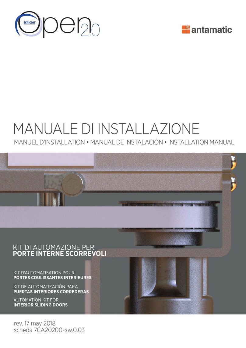
Scrigno antamatic OPEN 2.0 User manual

Scrigno

Scrigno antamatic OPEN 2.0 User manual

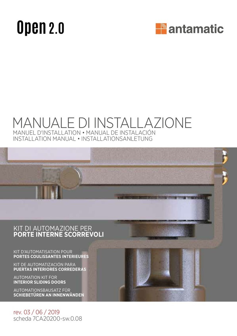
Scrigno antamatic OPEN 2.0 User manual

Scrigno

Scrigno antamatic OPEN 2.0 User manual

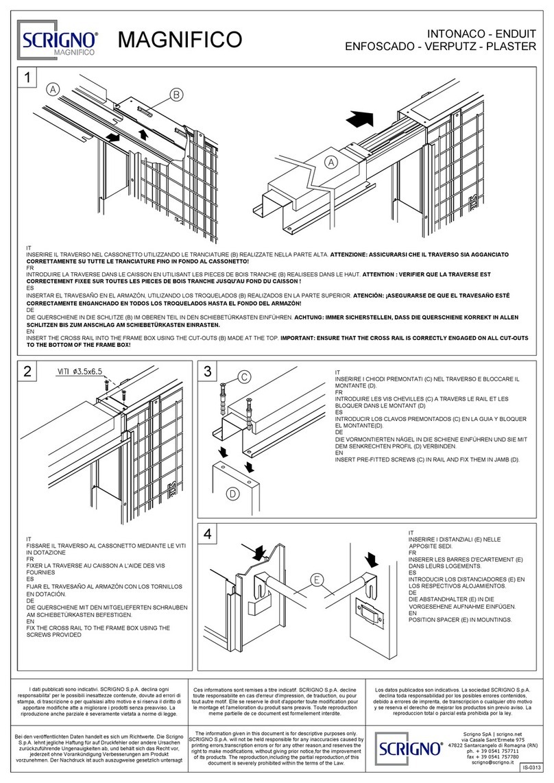
Scrigno MAGNIFICO User manual

Scrigno

Scrigno MAGNIFICO User manual

Scrigno OPEN1000 User manual

Scrigno

Scrigno OPEN1000 User manual

Popular Door Opening System manuals by other brands

Mobeye Call-Key MCK100 installation manual

Mobeye

Mobeye Call-Key MCK100 installation manual

SALICE Lapis Assembly instructions

SALICE

SALICE Lapis Assembly instructions

Cal-Royal N-F77CVR Installation instruction

Cal-Royal

Cal-Royal N-F77CVR Installation instruction

BFT WIND RMB 130B 200 installation manual

BFT

BFT WIND RMB 130B 200 installation manual

Alecto ADI-250 user manual

Alecto

Alecto ADI-250 user manual

Besam Swingmaster MP Installation, adjustment and maintenance instructions

Besam

Besam Swingmaster MP Installation, adjustment and maintenance instructions

Assa Abloy SARGENT 1431 Series instructions

Assa Abloy

Assa Abloy SARGENT 1431 Series instructions

GAL MOVFR Quick setup

GAL

GAL MOVFR Quick setup

Häfele Finetta T 70 VF manual

Häfele

Häfele Finetta T 70 VF manual

AGS D-PL Instructions for fitting, operating and maintenance

AGS

AGS D-PL Instructions for fitting, operating and maintenance

Stanley MA900ñ Installation and owner's manual

Stanley

Stanley MA900ñ Installation and owner's manual

WITTUR Hydra Plus UD300 Instruction handbook

WITTUR

WITTUR Hydra Plus UD300 Instruction handbook

Alutech TR-3019-230E-ICU Assembly and operation manual

Alutech

Alutech TR-3019-230E-ICU Assembly and operation manual

Pamex KT-INP35 Installation instruction

Pamex

Pamex KT-INP35 Installation instruction

MPC ATD ACTUATOR 50 ATD-313186 Operating and OPERATING AND INSTALLATION Manual

MPC

MPC ATD ACTUATOR 50 ATD-313186 Operating and OPERATING AND INSTALLATION Manual

Chamberlain T user guide

Chamberlain

Chamberlain T user guide

Dorma MUTO COMFORT M DORMOTION 50 Mounting instruction
Dorma

Dorma MUTO COMFORT M DORMOTION 50 Mounting instruction

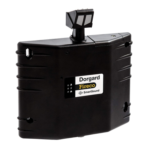
Fireco Dorgard operating guide

Fireco

Fireco Dorgard operating guide
manuals.online logo
manuals.online logoBrands
  • About & Mission
  • Contact us
  • Privacy Policy
  • Terms and Conditions

Copyright 2025 Manuals.Online. All Rights Reserved.

10 mm
max. 2700 mm
max.
100 kg
C
o
m
p
o
s
i
t
i
o
n
o
f
k
i
t
SC3110
SC3100
SC3140
SC3120
SC3140
KF-SC31-R0_EN PAGE 2 of 15
i
m
p
o
r
t
a
n
t
i
n
f
o
r
m
a
t
i
o
n
•
•
•
•
•
•
•
•
•
•
•
•
•
•
•
•
•
•
•
•
KF-SC31-R0_EN PAGE 3 of 15
20
43
20
27
10
10
H=opening height
LG
H
Lv
31
15
10
hv=H-10
35
flush with wall
p
r
i
n
c
i
p
l
e
s
o
f
p
l
a
n
n
i
n
g
DIAGRAM OF WALL OPENING AND CROSS-SECTION
LG = Track length H = Opening height Lv = Opening width
VM
Sliding door with
handle
RECOMMENDED
GLASS: 10 mm
TEMPERED
KF-SC31-R0_EN PAGE 4 of 15
VM
LV LV
LG
VM
LV
VM
LV
LG
H
Lv
OPENING DIAGRAMS
VM = Glass door with handle
LV = Opening width
Overlap
on handle side
S = 20 mm
recommended
Floor guide width 50 mm to be
positioned flush with the door
VM = LV + 50 + S
LG = 2 (LV + S) + 50
LV = LG - 50
2- S
VM = LV
2+ 50
LG = Track length
S = Overlap on handle side
VM = LV
2+ 50 Floor guide width 50 mm to be
positioned flush with the door
Floor guide width 50 mm to be
positioned flush with the door
KF-SC31-R0_EN
p
r
i
n
c
i
p
l
e
s
o
f
p
l
a
n
n
i
n
g
PAGE 5 of 15
2Lv + 100 mm
Lv
p
r
e
p
a
r
a
t
i
o
n
a
n
d
c
u
t
t
i
n
g
o
f
c
o
m
p
o
n
e
n
t
s
1. Measure the width Lv of the wall opening.
2. Mark profile bars SC3110 and SC3120 for cutting to size at
the distance of 2Lv + 100 mm.
3. Cut the profile bars to size using specific cutting tools and
suitable personal protective equipment. Take care to avoid
bending the profile bars during cutting operations.
IMPORTANT:
Cutting with a diamond disc blade reduces
profile bar length by about 4-5 mm due to
the thickness of the blade itself. This must
be taken into consideration when making
measurements.
SC3110
SC3120
AVVERTENZA:
verificare che il supporto
orizzontale superiore sia
a livello.
1
2
KF-SC31-R0_EN PAGE 6 of 15
Lv
ii
i
4. Place the profile bar at a height of min. H+59 mm, keeping it pressed firmly against
the fixing surface (masonry or other materials).
5. Mark the support surface through the holes in the profile bar to indicate the position
of the holes to be drilled.
6. Drill the support surface and insert the fixing accessories (expansion plugs or other
fixings depending on the type of support surface).
4
WARNING!
The expansion plugs shown in
the diagram are only one of the
possible fixing methods. The
installer must use the most
appropriate fixing accessories for
the material from which the
support surface is made.
N.B:
If necessary, drill additional holes in the
profile bar using the groove provided as a
guide (e.g. weight limit!!)
5
6
d
r
i
l
l
i
n
g
o
f
s
u
p
p
o
r
t
s
u
r
f
a
c
e
SC3110
KF-SC31-R0_EN PAGE 7 of 15
20
Ø5,5 Ø12
38
31
11
7
7. Fix the SC3110 profile bar to the wall using suitable fixing accessories.
8. Check that the screws are correctly tightened to ensure that their heads do not project, which
would prevent smooth sliding of the runners.
i
n
s
t
a
l
l
a
t
i
o
n
o
f
t
r
a
c
k
a
n
d
f
l
o
o
r
g
u
i
d
e
9
8
SC3110
10
9. Fix the floor guide at a distance of 20
mm from the line between the fixing
hole centres and the wall. Align the
short side flush with the inner side of
the wall opening.
10. After fixing, clean the inside of the SC3110 track
using a pressurized air jet or a vacuum cleaner.
Remove all residues of dust and dirt from the
track.
KF-SC31-R0_EN PAGE 8 of 15
+
+
a
s
s
e
m
b
l
y
o
f
h
a
n
g
e
r
s
a
n
d
e
n
d
s
t
o
p
s
11. Insert the hangers and end stops* into the SC3110 profile bar without fixing
them in their final positions, leaving them free to slide inside the profile bar.
12. Respect the sequence shown in the diagrams, ensuring that the hangers are
on the interior with respect to the end stops.
* If shock absorber Art. 32423 is envisaged
(for use of the shock absorber consult the specific instructions)
SC3110
11
12
KF-SC31-R0_EN PAGE 9 of 15
VM
70
141
13
13
16
R5
R5
min. 100
71
16
a
s
s
e
m
b
l
y
o
f
g
l
a
s
s
d
o
o
r
a
n
d
a
c
c
e
s
s
o
r
i
e
s
ALIGNMENT OF CLAMP WITH
UPPER EDGE OF GLASS
13
13. Thoroughly clean the contact surfaces between the glass and the
accessories.
14. Assemble the CERPOS170 clamps onto the glass door as indicated in the
diagram, taking care to follow the correct order of components as shown. As
a check, the countersunk heads of the clamp tightening screws must be
facing the wall. Use the appropriate spacers between the seals supplied in
the accessories pack according to glass thickness (e.g. for 10 mm glass use
two 1 mm seals).
15. Check that the upper edge of the clamp is flush with the edge of the glass.
14
15
GLASS DRILLING DIAGRAM
KF-SC31-R0_EN PAGE 10 of 15