SDI PORTAGAUGE 4 User manual

PORTAGAUGE® 4
USER MANUAL

Contents
2
1. Introduction and Key Features
1.1 What does the Portagauge®do?
1.2 The Portagauge® 4
1.21 The Portagauge® 4– Unit and Measuring Screen
1.22 The Portagauge® 4– Definition of Menu Items
1.3 How does a Portagauge® 4work?
2. Operating Instructions
2.1 Introduction
2.2 Preparation
2.21 Assembly
2.22 Probes
2.23 Probe Membranes
2.24 Calibration
2.25 Speed Table
2.3 Test Procedure
3. Maintenance
3.1 Probe Care
3.2 Battery Care
3.21 Battery Replacement
3
3
3
4
5
6
7
7
8
8
8
9
10
11
12
14
14
15
16

1. Introduction and key features
What does the Portagauge® do?
The Portagauge® 4is a portable, robust device used to accurately measure the
thickness of a material using multiple echo, ultrasonic technology.The Portagauge® 4is
capable of working across a large number of different applications and environments,
whether this be different surface conditions, the presence of rust, small curvature
surfaces or for any other maintenance and inspection requirement.The unit operates
on a wide range of metal materials (Steel/ Stainless Steel, Cast Iron, Aluminium,
Copper, Brass, Zinc, Grey Cast Iron).
Due to its use of ultrasonic methods, the Portagauge® 4only needs access to one side
of a surface to measure the thickness of the material.This enables the device to non-
invasively measure the wall thickness of metal pipes, tanks, beams and other such
structures without any risk of damage.
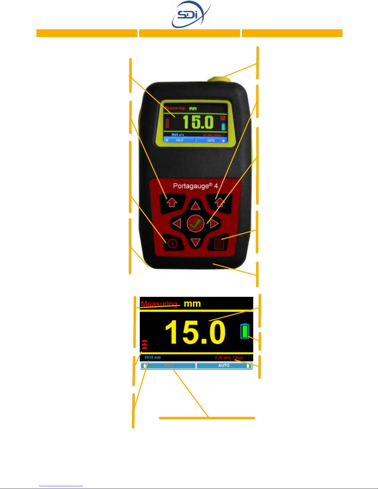
The Portagauge® 4
The Portagauge® 4is the most advanced and accurate model of the Portagauge®
range. Its use of multiple echo ultrasonic technology allows it to account for coatings
of up to 20 mm, ensuring that they are not included in the measurement of the
thickness of the material. Its design and function has been built on earlier models to
achieve this accuracy as well as its durability and consistency. The enclosure is rated to
IP 65 providing a high level of protection in even hard industrial environments.
3
HOLD
4
Battery
Compartment: The
battery compartment is at
the back of the unit. It
must be opened by a flat
head tool
Lemo Connector:
Allows for secure
fastening of the cable for
the sensor probe.
Units of Measurements:
The units of the
measurements can be
changed (inch/mm) by
navigating to the “Units”
section of the menu
Digital Display:
Numerical readings allow
users to determine the
thickness of the material
Echo Strength: The
greater the number of bars
the greater the strength of
the returning signal
BAT OK: Checks battery
level
Sealing: Black rubber
sealing for watertight
integrity IP 65
Directional Pad: The
directional pad allows
the items on the menu
and sub-menus to be
navigated using the left,
right, up and down keys
and selected using the
Enter/OK key at the
centre
Menu Button:
Accesses the menu for
the unit (see page 5 for
more information on
menu items).
Right Option Key:
Selects the option at
the bottom right of the
LCD screen
The Portagauge® 4
Display: Color LCD
display for access to the
Measuring screen and Menu
screen.
Left Option Key:
Selects the option at the
bottom left of the LCD
screen
ON/OFF Button Simple
power ON/OFF button –
powered by 3 x 1.5V AA
batteries providing
approximately 20 hours of
battery life. Keep turned
off when not in use to
save battery life
Measuring Screen
iProbe indicator:
Indicates the type of probe
connected
Velocity of Ultrasound:
Indicates the velocity of
the ultrasound travelling
through the material Hold Measurement: Fixes the
last thickness reading on the
screen when the Left Option
Key is pressed
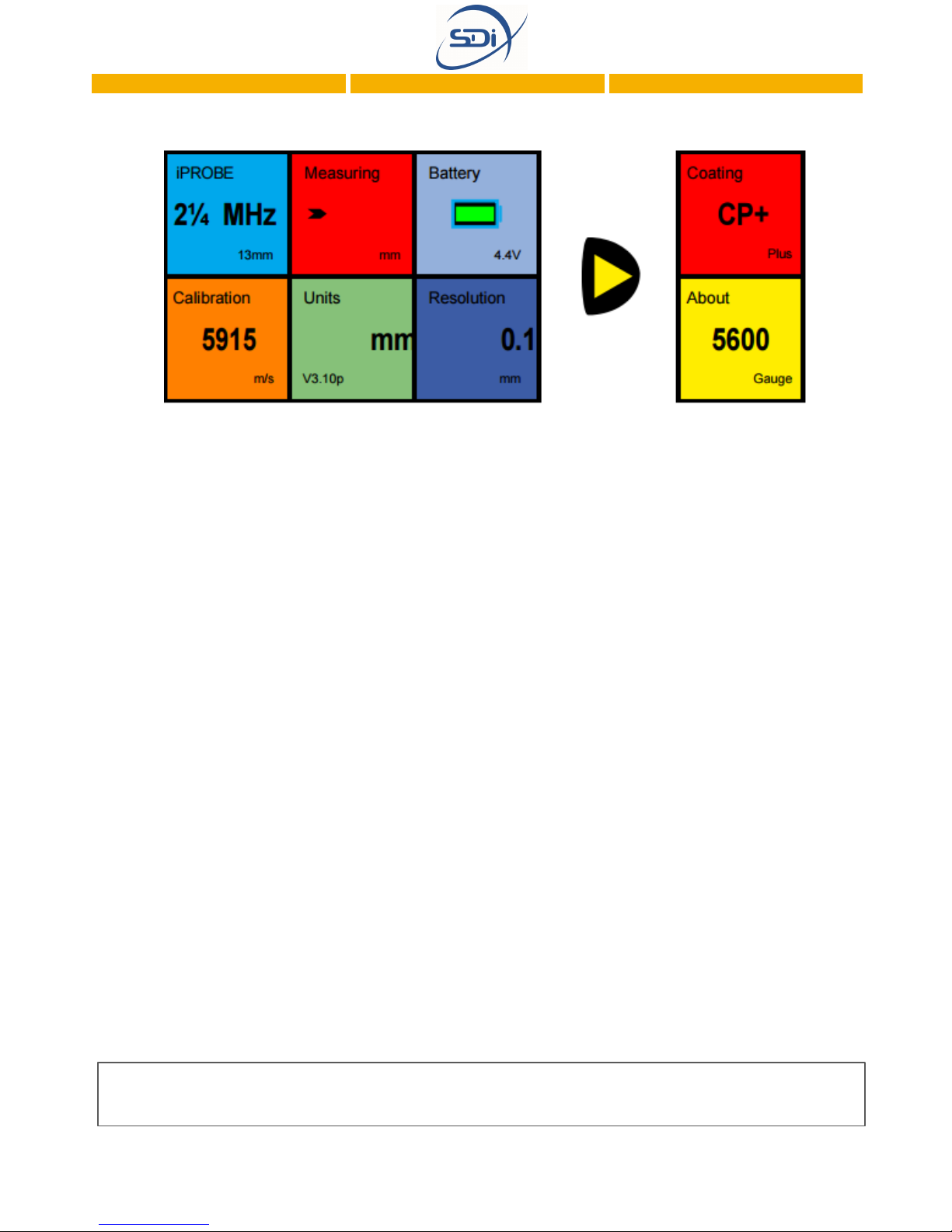
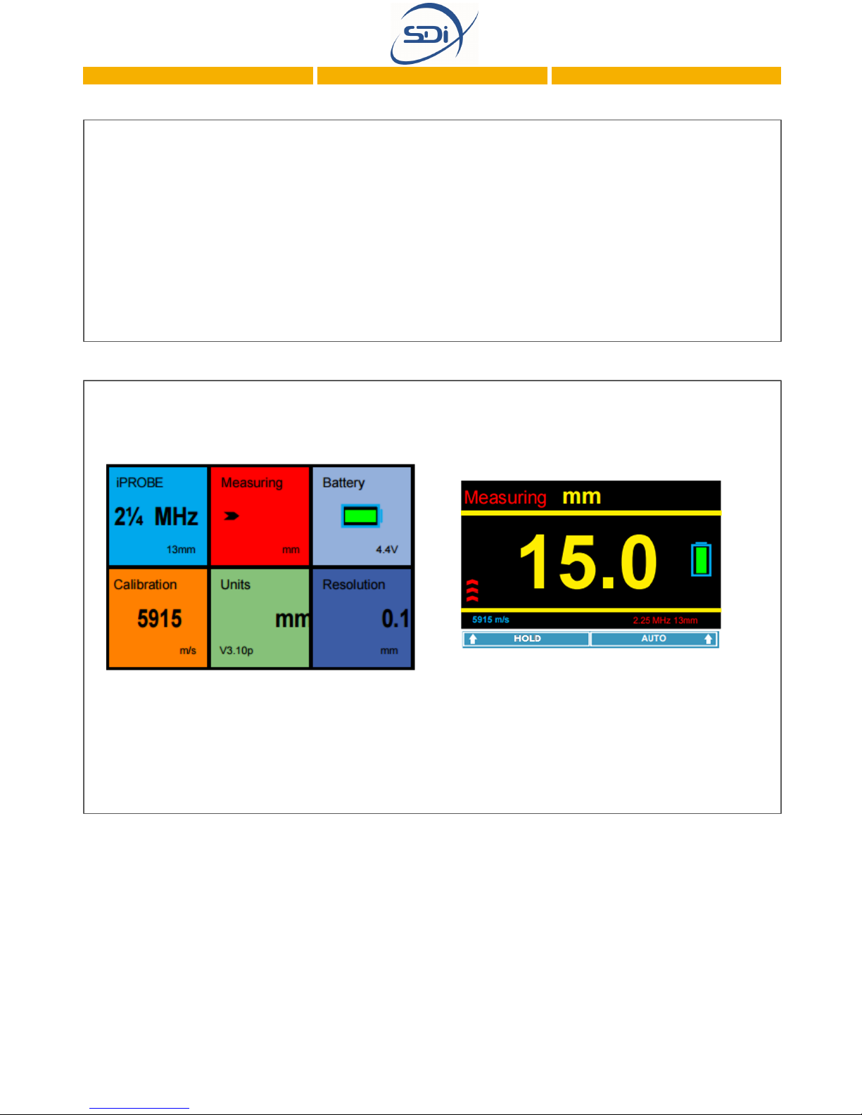
—Shows that an iProbe has been connected. The probes are
automatically recognised by the gauge and all the relevant
probe data is transferred to the gauge to perfectly match the
probe to the gauge for optimum performance.
—All materials have varying velocity of sound properties and
this section allows the gauge to be calibrated for the different
materials that the gauge can measure.
—Displays the measurements being taken by the gauge.
—The measurements can be displayed in metric or imperial.
—Displays the remaining battery life. The green changes to
yellow when the battery is getting low and then changes to
red when the batteries are critically low.
—The measurements can be displayed to a resolution of
0.05mm or 0.1mm.
—Allows measurements to be taken through extremely thick
coatings up to 20mm, depending on the type of coating. In
normal mode the gauge can still ignore up to 6mm of coating.
—Displays the software and firmware versions and includes a
facility to reset the gauge to factory settings.
5
iProbe
Calibration
Measuring
Units
Battery
Resolution
Coating
Plus+
About 5600
Definition of Menu Items
Note: The “Coating Plus” and “About 5600” menus items may be found by pressing the right
key on the directional pad.

How does a Portagauge® 4 work?
All sound is physical vibrations which move through a material, and in the case of the
sound we are used to, the vibrations move through air. Ultrasound is the same as the
sound we experience, but its frequency is beyond that which humans are capable of
hearing. Whilst the highest frequency a human can hear is around 20,000 Hz,
Portagauge® 4 units use sound at a frequency of 2.5 MHz, 3.5 MHz or 5 MHz
depending on the specific probe being used.
All Portagauge® devices use ultrasound to measure the thickness of a material. The
unit sends a strong electrical signal to the probe, causing it to emit a high energy pulse
of ultrasound. The transmitted ultrasound pulse travels though both the coating and
the metal and reflects from the back wall. The returned echo then reverberates within
the metal, with only a small portion of the echo travelling back through the coating
each time (Figure 1). The timing between the small echoes gives the timing of the
echoes within the metal, which relate to the metal thickness. The returned echoes
need not be consecutive as the gauge will interpret them automatically and calculate
the thickness. A minimum of three echoes are checked for each pulse that is sent into
the metal.
6
Timing 1
Figure 1

7
2. Operating Instructions
DO NOT PROCEED BEFORE READING SECTION 1.
There are two basic procedures which must be carried out when using
the Portagauge® 4:
1. Preparation: Calibration ensures that the Portagauge®equipment functions
properly for the specific metal being tested.
2.Testing: After step one, you can follow the appropriate testing procedure.

8
1. PREPARATION
Preparation for testing is simple, quick and ensures you get the most reliable and
accurate results from your testing. It ensures the equipment is assembled correctly
and that the appropriate probe is selected. Calibration ensures that the unit and
probe work correctly for the specific metal being tested.
Assembly
To assemble the gauge for use:
STEP 1: Attach the probe to the probe cable by pushing the cable Lemo
plug into the socket on the probe.
STEP 2: Connect the other end to the gauge Lemo socket (see page 4).
To remove the connectors, simply pull back on the connector collars to release the
plug from the socket. Do not force or twist under any circumstances.
Probes
The probes used with the Portagauge® 4thickness gauges are single
crystal soft faced probes.The table below identifies the different probe
options and which probe is the most suitable for different applications.All
probes are color coded to help identify their frequency.
Frequency
2.25 MHz
3.5 MHz
5 MHz
Measuring
Range
3 –250 mm
(0.120” to 10”)
2 –150 mm
(0.080” to 6”)
1 –50 mm
(0.040” to 2”)
Color Yellow Green Blue
Diameters
Available
13 mm (0.5”) & 19
mm (0.75”)
13 mm (0.5”)
6 mm (0.25”) & 13
mm (0.5”)
Suitable For
Most thickness
gauging
applications.
Works particularly
well on heavy
corrosion,
especially the 19
mm probe.
Will measure
relatively thin
metal which is
corroded.
Normally used
only if measuring
down to 2 mm is
of importance.
Ideal for
measuring thin
metal in relatively
good condition.
Not advisable to
use as main probe.
Note:The details of the probe connected are recognized and displayed on the
Measuring Screen, as seen on page 4, or under the iProbe item on the Menu, as seen
on page 5.

9
Probe Membranes
All probes are fitted with protective membranes to help prolong the life of the
probe.The membranes also provide a flexible interface which acts as an aid
when working on rough surfaces. Membrane wear should be monitored and
checked at regular intervals.
NormalTemperature Membranes
Standard membranes allow measurements to be taken on hot surfaces up to a
maximum of 158°F(70°C).
HighTemperature Membranes
Teflon™ membranes are available for measurements on hotter surfaces. In this
case measurements can be taken on surfaces up to 302°F(150°C). Care
should be taken that the probe does not overheat.The probe should be
allowed to cool down in between each measurement.A high temperature
ultrasonic gel is advised for this application.
Note: All probes should be treated with care. When taking measurements, they should not
be scraped or dragged along the surface. Although the membranes will protect the probe
against everyday wear and tear, they will not protect against rough treatment and misuse.

10
Calibration
The gauge should be calibrated to the type of material that is being measured.This is
because ultrasound travels at different speeds in different materials.
There are two methods of changing the calibration. Either adjust the velocity of sound
setting according to the metal being measured, or adjust the gauge to a known
thickness of metal.
Gauges are supplied with the calibration set to mild steel at approximately 5900 m/s.
This may vary according to the properties of the supplied 15 mm test block material.
Calibrating to the Velocity of the Ultrasound
STEP 1: Navigate to ‘Calibration’ on the ‘Menu’ screen using the keys on the
directional pad (see page 4). Use the Definition of Menu Items on page 5 as a guide.
STEP 2: Press the ‘OK’ button at the centre of the directional pad.
STEP 3: Use the left and right buttons on the directional pad to adjust the velocity of
sound to the required new velocity that the ultrasound travels at in the material being
tested.Approximate values for these may be found on page 11.
STEP 4: Press the ‘Right Option Key’, the gauge will save the new calibration and
return to the ‘Menu’ screen.
Calibrating to a KnownThickness
STEP 1: Navigate to ‘Calibration’ on the ‘Menu’ screen using the keys on the
directional pad. Use the Definition of Menu Items on page 5 as a guide.
STEP 2: Press the ‘OK’ button at the centre of the directional pad.
STEP 3: Place the probe on a piece of material of known thickness such as the 15mm
test block supplied with the kit.
STEP 4:Adjust the measurement displayed to the known thickness using the left and
right buttons on the directional pad.
STEP 5: Press the ‘Right Option Key’, the gauge will save the new calibration and
return to the ‘Menu’ screen.
Note:The calibration does not need to be reset each time the gauge is used.The last setting
will be remembered.

11
Speed Table
The given values are in certain cases strongly dependent on the alloy, heat treatment,
manufacturing and processing and are therefore only approximate standard values.
They are given here as a guide only.
Reference: Mathies, Klaus (1998), Thickness Measurement with Ultrasound, Berlin: German Society of
Nondestructive Testing.
Material
Speed
–m/s
Aluminium
Rolled
Duraluminium
6200 –6360
6420
6320
Bronze (5%P)
3531
Copper
3666 –4760
Glass, Plate
5766
Inconel, Forged
7820
Lead
2050 –2400
Steel, Mild
SuppliedTest Block
5890 –5960
5900 approx.
Steel, Stainless
10 Cr Ni 18 8, ann
5530 –5790
5530
Steel
,Tool
C105 Annealed
C105 Hardened
5490 –5960
5854
Tin
3210 –3320
Titanium
5823 –6260
Zinc
3890 -4210

2. TESTING with the Portagauge® 4
PRECAUTIONS:
Check that the material has parallel front and back walls. If the front and
back walls are not parallel, the ultrasound hitting the back wall will be deflected away
from the face of the probe.The probe will therefore not receive any echoes back.
The surface being measured should be free from dirt or debris. It may be
necessary to clean or brush the surface prior to taking measurements.
Ensure the coating is not layered or does not contain foreign objects in its
construction. Layered coatings cause reflections at the layer interface.This seriously
weakens the strength of the ultrasound and may prevent it from travelling all the way
through.The same applies to foreign objects which can deflect the ultrasound path or
prevent the ultrasound from passing.
Ensure the coating is solidly adhered to the surface. Triple echo will ignore
coatings as long as they are solidly adhered to the surface. If the coating has become
loose or delaminated then air pockets will exist which interfere with the Ultrasound.
PROCEDURE:
STEP 1: Unscrew the probe knurled ring and apply a few drops of membrane oil to
the face of the probe. Do not apply too much membrane oil underneath the
membrane. Once fitted, the membrane should be flat with no air bubbles trapped
behind.
STEP 2: Re-screw the knurled ring, ensuring there are no air pockets.
STEP 3: Connect the probe, cable and gauge together (see page 8).
STEP 4:Turn on the gauge using the ON/OFF button (see page 4).
STEP 5:The normal measurement mode will ignore coatings of up to approximately 6
mm. If a coating between 6 mm to 20 mm exists then the Coating Plus+ mode,
accessed by navigating to the right of the Menu screen (see page 5) using the arrow
keys on the directional pad and selecting the feature using the ‘OK’ button, can be
turned on to measure the metal thickness in such cases.
Note: If a compatible probe other than an SDi probe is attached to the unit, the gauge will
automatically detect this and display the message “Unrecognised Probe”. If this occurs
press the “OK” button and then select the correct parameters (frequency and diameter) for
the probe being used.
12
13
The Coating Plus+ feature is automatically switched off when the unit is turned off. If
this feature is required permanently, press the ‘Right Option Key’ labelled “SAVE” to
keep this as a permanent setting.The CP+ icon will be displayed on the right of the
Measuring screen if the feature is selected.
STEP 6: Navigate using the arrow keys on the directional pad to the ‘Measuring’ item
on the Menu screen. Press the ‘OK’ button to access the Measuring screen.
STEP 7: Apply a small amount of gel to the surface being measured to eliminate the
possibility of air pockets between the surface and the probe.
STEP 8: Apply the probe firmly to the surface, ensuring good contact, and take the
measurement. It may sometimes be necessary to rock the probe slightly and gently in
order to obtain measurements (only do so if you are having trouble obtaining
measurements).
STEP 9: If you wish to hold a measurement, press the ‘Left Option Key’ whilst
readings are being taken. The display will hold the measurement and flash ‘Holding’ in
the top right corner of the LCD screen. Measuring may be resumed by pressing the
‘Left Option Key’ again which is now labelled “Resume”.
STEP 10: Remove debris from the probe face between measurements.
Note: If the message “No Probe connected” appears, either connect a suitable probe or
simply press the “OK” button to enable the navigation of the menus without a probe fitted.
No measurements can be taken if a probe is not detected.
Note: The Coating Plus+ mode should not be left on for all measurements.The gauge will
achieve a better performance on standard coatings with this function turned off.
Note: The units and resolution of measurements can be changed using the respective
options on the Menu screen (see page 5).

14
3. Maintenance
This section contains instructions on how to maintain the equipment to extend its
lifetime as long as possible. Maintenance of the equipment is simple and only requires
the cleaning of the probe and battery care. For any major works or re-calibrations
the unit can may need to be sent to the manufacturer for repair.
Probe Care
The ultrasonic probe is the most delicate part of a Portagauge®, and care must be
taken when using it. After using a Portagauge®, it is essential to ensure that the probe
is dried off and free from dirt.The probe is robust, but damage may occur if it is
dropped, or if the probe is dragged across the surface rather than being removed and
replaced. Never try to repair a probe or try to remove scratches from the face of
the probe.This may result in further damage.Always return it to SDi for investigation
and possible repair.
The membrane requires changing from time to time to ensure the protection of the
probe and the prolonging of its lifetime. See below for instructions on how to change
this membrane.
STEP 1: Unscrew the knurled ring (1) from the probe (4).
STEP 2: Using the membrane key (5), remove the retaining ring (3) from
inside the knurled ring (1).
STEP 3: Push the old membrane (2) out from the front.
STEP 4: Fit a new membrane (2) from the back and push it down until it
locates in the groove on the inside front edge.
15
Battery Care
The Portagauger® 4has a battery indicator on the right of the ‘Measuring’ screen and
on the top right of the ‘Menu’ screen.
When the battery is indicated to be low on power, the battery must be replaced
before it is used further, or the unit may provide anomalous results.
When a Portagauge®unit is going to be stored, or not used for a long period of time,
remove the battery from the main unit to prevent corrosion damage to the unit.
STEP 5: Refit the retaining ring (3) and secure it in place using the
membrane key (5).
STEP 6: Place a few drops of membrane oil (6) onto the face of the probe
(4). Do not use too much.
STEP 7: Screw the knurled ring (1) back onto the probe (4) whilst applying
pressure on the membrane (2) with the thumb to expel any air
from behind the membrane.
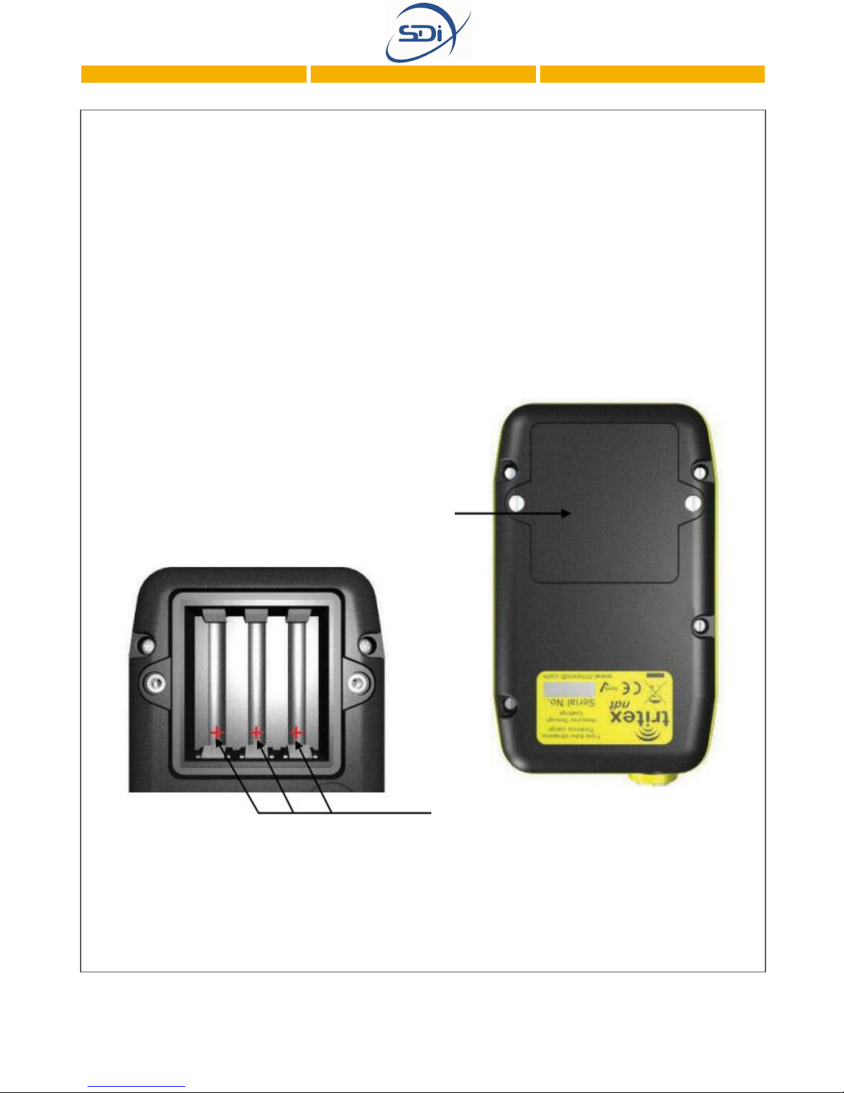
Battery Replacement
You will need a small flathead screwdriver and three 1.5V AA batteries.
STEP 1: Ensure the unit is off and turn the unit so that the front fascia faces
downwards.
STEP 2: Take a small, flat head screwdriver and unscrew the two screws holding down
the hatch of the battery compartment.
STEP 3: Lever the screwdriver gently to remove the hatch.
STEP 4: Remove the old batteries and replace with the new, taking care to connect +
and –correctly.
STEP 6: Close battery cover, ensuring that the wires are not trapped.
STEP 7: Press battery hatch and use the screwdriver to replace the screws so that
the hatch of the battery compartment is closed once again..
16
Battery Compartment
Positive
Terminals (+)
Table of contents
Other SDI Measuring Instrument manuals


