SDI PORTALEVEL MAX User manual

PORTALEVEL® MAX
USER MANUAL

Contents
2
Note: For information on converting Liquid Levels to approximate agent weights,
see the separate guide ‘Liquid Level to Weight Conversion,’also on sdifire.com/support.
1. Introduction and Key Features
1.1 What does the Portalevel®do?
1.2 The Portalevel®Max
2. Operating Instructions
2.1 Introduction
2.2 Preparation
2.21 Function Test
2.22 Dip Test
2.23 Cylinder Preparations
2.24 Temperature
2.3 Calibration Procedure Identification (CPI)
2.31 Test Procedure 1
2.32 Test Procedure 2
2.4 Troubleshooting
2.5 Frequently Asked Questions
3. Accessories
3.1 Extension Rod
3.2 Portatherm®
3.3 Ultrasonic Gel
3.4 Portalevel®Sensors
4. Maintenance
4.1 Sensor Care
4.2 Battery Care
4.21 Battery Replacement
4.3 Storage
5. Training
5.1 The Bench Test
3
3
3
6
7
7
7
8
8
9
10
12
14
19
21
21
23
24
24
25
25
25
26
26
27
27

1. Introduction and key features
What does the Portalevel®do?
The Portalevel®Max is designed to be a portable way to non-invasively locate the
liquid level inside any single skinned cylinder. Portalevel®s are capable of detecting the
presence of any liquid externally; from water and liquid pressurised gases to
firefighting clean agents. Portalevel®s can be used on a huge variety of container types,
composed of different materials and of different shapes and sizes, but are typically
most used on steel compressed gas cylinders.
Many applications exist for our technology, but it is most widely used as a
replacement to both weighing fire suppression cylinders during installation and
servicing, or the fitting of internal and invasive liquid level ‘float’ devices. Once the
liquid height inside a container has been found, the contained weight of liquid can be
determined, after taking into consideration other environmental factors such as the
size of the cylinder and type of liquid.
Portalevel®Max
With an intelligent calibration feature and four separate power settings, the
Portalevel® Max is versatile and our most user friendly unit. It is capable of testing a
wide variety of fire suppressant agents; CO2, FM200™, NOVEC 1230™, old Halon
agents, FE-13™, FE-25™, NAF S III™ and all core Clean Agent Systems.
3

Portalevel®Max
The Portalevel®Max also includes; sensor, and ultrasonic gel (couplant).
Gromit: The gromit at
the top of the unit is
the ultra secure simple
fastening for the sensor
Sealing: Red sealing
ring for watertight
integrity
Display: ‘Go/No-Go’
readings for quick and
easy use
On: Simple power ON
button – powered by 1
x 9V battery providing
approximately 8 hours
battery life
Off: Simple power OFF
button – keep turned
off to save battery life
SPA: The SPA capability
enables an increased
strength of signal output to
achieve better readings for
poor condition cylinders,
more challenging
applications and large
volume uses.
CAL: The CAL button is
the standard procedure
feature enabling self-
calibration prior to testing
on each individual cylinder,
to ensure accurate and
reliable readings.
Battery
Compartment: The
battery compartment is
on the bottom of the unit
and has a double gateway
to be waterproof. It must
be opened by a flat head
tool, e.g. a screwdriver in
order to change the
battery.
V1.02: Version 1.02
Digital display:
Numerical readings for
experienced users to
gauge a better
interpretation of the
ultrasound behaviour
Bar graph display: Easy
to interpret visual reading
CAL: Highlights when
CAL in use
SPA: Checks SPA feature
is working
BAT OK: Checks battery
level
4
5
2. Operating Instructions
POINTS TO CONSIDER BEFORE PROCEEDING:
!Do not proceed before reading section 1.
!Do not proceed before familiarising yourself with the Training section on page 27.
Introduction
There are three basic procedures which must be carried out when using the
Portalevel®Max:
1. Preparation: Function Tests and cylinder preparations.These tests ensure that the
Portalevel®equipment is functioning properly and that the cylinder(s) are prepared in
a way to give the most accurate readings.
2. Calibration Procedure Identification (CPI): This test allows you to determine
which method of testing should be used on the cylinders you wish to measure. Once
you know the appropriate method of testing for that type of cylinder, you do not need
to perform this again for that testing session.
3.Testing: After step two, you can follow the appropriate testing procedure (1 or 2)
for that set of cylinders.
Note: If you move on to testing a different type of cylinder, which is a different size, weight or
filled with a different agent, you must repeat step 2 on the new cylinder type to confirm
which testing procedure is required.
As with all electronics, do to leave the Portalevel® Max in the
sun for long periods of time. Excessive UV exposure can lead
to damage of the LCD screen.

6
1. Preparation
Preparation for testing is simple, quick and ensures you get the most reliable and
accurate results from your testing.The FUNCTION Test and DIP Test both ensure the
main unit and sensor are working correctly. CYLINDER PREPARATIONS ensure that
you test on the best possible area of the cylinder wall.
FUNCTION Test:
A FUNCTION Test should be performed every time you wish to use the unit.To
perform the test, simply connect the sensor to the main unit and turn on the
Portalevel®.After a couple of seconds, the readout should reset itself to zero.Then
press the CAL button.The CAL symbol should become blacked out like this:
Then disengage CAL by pressing the CAL button again and turn the unit off.This
completes the Function Test.
DIP Test:
The DIP Test checks whether the sensor you are using is working correctly and is
communicating with the Portalevel®main unit.
Step 1: Connect sensor to unit and turn on.
Step 2: Lightly dip the tip of sensor into cup of water vertically.The amount of water in
the cup is not important, as long as there is enough to dip the end of the sensor so the
black central patch on the end of the senor is submerged, without it touching the
bottom of the cup.
Step 3:When dipping the sensor, you should see the readings of the Portalevel®spike
to high values and the bar graph rise also. If you do observe this, then the DIP Test is
complete and you know the sensor is working well.!

7
CYLINDER PREPARATIONS:
It is important to prepare the cylinders well to attain accurate and reliable readings.To
perform CYLINDER PREPARATIONS:
Step 1: Find on the cylinder the side which has the least damage, rust or chipped paint.
For accurate testing you must find a vertical strip down the side of the cylinder which
is as smooth as possible.You will be placing the sensor and testing along this strip.
Step 2:Wipe down the chosen side of cylinder with damp cloth to remove dirt and
debris.This completes the CYLINDER PREPARATIONS.
IF YOUR UNIT FAILS THE FUNCTION OR DIP TEST, PLEASE
CONTACT SUPPORT AT (732)-751-9266 OR
SERVICE@SDIFIRE.COM
Temperature:
The surface temperature of the cylinders stored must be measured before the liquid
levels are checked. This should be measured around half way up the cylinder.
IF THE TEMPERATURE EXCEEDS 86oF (30°C) DO NOT TEST CO2or
FE-13 CYLINDERS.
Further information regarding this issue can be found on page 20 under Frequently
Asked Questions.

8
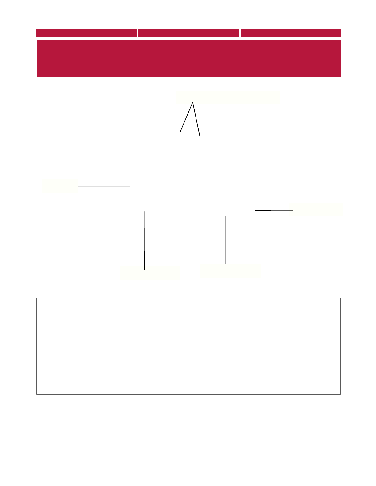
To perform CPI:
Step 1: Place a strip of gel or water down the vertical strip on the cylinder you chose
during CYLINDER PREPARATIONS.
Step 2: Place sensor at top of cylinder (below top wield seam or curve).Take note of
digital reading.
Step 3: Place sensor 5cm below. (Take note of digital reading).
Step 4: Repeat Step 3 down the full vertical length of the cylinder.
Step 5: Analyse the results using the guide below.
2. Calibration Procedure Identification (CPI)
The purpose of this test is to identify whether method 1 or 2 should be used for
the cylinder being tested.The details and differences between methods 1 and 2 are
explained in the next section.
Compare your results to the guide below to decide whether Procedure 1
or Procedure 2 should be used when testing the cylinders you wish to
measure.
INSTANCE 1:“Higher readings were found in the upper portion (gas area) of the
cylinder compared with the lower portion (liquid area).” – Carry out Procedure 1.
INSTANCE 2:“Higher readings were found in the lower portion (liquid area) of the
cylinder compared with the upper portion (gas area).” – Carry out Procedure 2.
INSTANCE 3:“There was no difference in readings between the upper portion and
lower portion of the cylinder” – Carry out Procedure 2.
Both Procedure 1 and 2 are fully explained in the next section.

9
3.Testing
PROCEDURE 1:TO BE USED WHERE HIGHER READINGS ARE FOUND
IN THE GAS PHASE COMPARED TO THE LIQUID PHASE.
Step 1: Place a strip of gel or water down the vertical strip on the cylinder you chose
during CYLINDER PREPARATIONS.
Step 2: Place the sensor on the area covered with gel or water and on the UPPER
portion of the cylinder, where you are certain the sensor will be above the liquid level.
DO NOT place the sensor close to the upper weld or start of the dome, as
anomalous readings will be found.
Note: The sensor must always be positioned with the ‘TOP’ marking positioned pointing
exactly upwards. On some sensors the ‘TOP’ is marked by a simple dot. If the sensor is not
accurately placed the right way up, then anomalous readings will be found.
Step 3: Once location has been found, press CAL. A full bar graph will appear on the
Portalevel®screen, example below:
Above liquid level
Calibration must be carried out for each individual cylinder tested.
Step 4: Move sensor 5cm down, observing the bar graph.
Note:When moving the sensor, it is important NOT to slide it, as this will damage the sensor
pad, rendering the sensor inefficient and inaccurate. Remove the sensor fully and replace in
steps each time you move the sensor.
Step 5: Repeat Step 4 until the bar graph reduces and disappears (example below). In
some areas the bar graph may ‘bounce’ up and down for a few seconds. If this occurs,
simply wait for the bar graph to settle.

10
Below liquid level
Note: Some cylinders are prone to giving ‘false levels’;that is the bar graph may disappear
after moving the sensor even though the Liquid Level has not been passed. If you think you
may have found a false Liquid Level, simply move the sensor slightly to the left or right to
check if the bar graph returns, as false levels can usually be caused by irregularities in a
specific part of the steel wall.
Step 6: Move sensor back up the cylinder in smaller steps until the bar graph rises
again.The position of the sensor on the wall of the cylinder at this point is the Liquid
Level position inside the cylinder. You have found the Liquid Level.
Note: For increased accuracy, it is possible to move the sensor in very small steps further up
or down to find the position where the bar graph settles in the middle of its range (neither
full or empty).At this point, the Liquid Level can be identified at the position of the exact
middle of the sensor with an uncertainty of ±1.5mm.
IF YOU ENCOUNTERED DIFFICULTY USING PROCEDURES 1 OR 2
PLEASE MOVE ONTO TROUBLE SHOOTING ON PAGE 14.

11
PROCEDURE 2: TO BE USED WHERE HIGHER READINGS ARE
FOUND IN THE LIQUID PHASE COMPARED TO THE GAS PHASE.
Step 1: Place a strip of gel or water down the vertical strip on the cylinder you chose
during CYLINDER PREPARATIONS.
Step 2: Place the sensor on the area covered with gel or water and on the LOWER
portion of the cylinder, where you are certain the sensor will be below the Liquid
Level. DO NOT place the sensor close to the weld or very close to the bottom of
the cylinder, as anomalous readings will be found.
Note: The sensor must always be positioned with the ‘TOP’ marking positioned pointing
exactly upwards. On some sensors the ‘TOP’ is marked by a simple dot. If the sensor is not
accurately placed the right way up, then anomalous readings will be found.
Step 3: Once location has been found, press CAL. A full bar graph will appear on the
Portalevel®screen, example below:
Below liquid level
Calibration must be carried out for each individual cylinder tested.
Step 4: Move sensor 5cm up, observing the bar graph.
Note:When moving the sensor, it is important NOT to slide it, as this will damage the sensor
pad, rendering the sensor inefficient and inaccurate. Remove the sensor fully and replace in
steps each time you move the sensor.
Step 5: Repeat Step 4 until the bar graph reduces and disappears (example below). In
some areas the bar graph may ‘bounce’ up and down for a few seconds. If this occurs,
simply wait for the bar graph to settle.

12
Above liquid level
Note: Some cylinders are prone to giving ‘false levels’, that is the bar graph may disappear
after moving the sensor even though the Liquid Level has not been passed. If you think you
may have found a false Liquid Level, simply move the sensor slightly to the left or right to
check if the bar graph returns, as false levels can usually be caused by irregularities in a
specific part of the steel wall.
Step 6: Move sensor back down the cylinder in smaller steps until the bar graph rises
again.The position of the sensor on the wall of the cylinder at this point is the Liquid
Level position inside the cylinder. You have found the Liquid Level.
Note: For increased accuracy, it is possible to move the sensor in very small steps further up
or down to find the position where the bar graph settles in the middle of its range (neither
full or empty).At this point, the Liquid Level can be identified at the position of the exact
middle of the sensor with an uncertainty of ±1.5mm.
IF YOU ENCOUNTERED DIFFICULTY USING PROCEDURES 1 OR 2
PLEASE MOVE ONTO TROUBLE SHOOTING ON PAGE 13

13
Troubleshooting
ISSUE 1:“The readings on the main unit did not change when the sensor
was placed anywhere on the cylinder”
SOLUTION: Firstly, ensure you are using an adequate quantity of water or gel to
couple the sensor to the cylinder and also ensure that the rubber pad of the sensor is
clean and undamaged.
If this does not solve the problem, carry out the DIP Test and the FUNCTION Test
found in section 2.2, page 7. If the sensor fails the DIP Test or the main unit fails the
FUNCTION Test then contact service@sdfire.comas the equipment is likely
malfunctioning.
ISSUE 2:“The readings fluctuate greatly even with the sensor repeatedly
placed on the same side of the Liquid Level.” / “Readings on the main unit
increase the longer the sensor is left on the cylinder.”
Some fluctuation in the reading is normal when working with this and any other
ultrasonic equipment. If the variation is extreme, ensure the end of the sensor and the
area of the cylinder you are testing are clean and free of debris and chipped paint.
You can expect the readings to rise once you have placed the sensor on cylinder,
especially when using the gel couplant.This rising of the reading values is caused by a
few separate factors, but does not prevent accurate Liquid Level detection.To reduce
the impact of this effect, try to keep the sensor on the cylinder for roughly the same
amount of time for every step up or down the cylinder you take with the sensor.
If the readings fluctuate more than ±100% when the sensor is left in one location
then please contact service@sdifire.com

14
ISSUE 3:“Readings are rarely/never greater than 1000 on the side of the
level where the highest readings are found.”
SOLUTION:The Portalevel®Max should, in most scenarios, be able to attain readings
of more than 1000 on a cylinder. Achieving readings less than 1000 DOES NOT
always prevent measurement, but in some cases may cause problems. If you are having
problems making a measurement:
Step 1: Clean surface of cylinder with damp cloth to remove dirt, debris, flaking paint
and rust. Choose a vertical strip on the cylinder which has the most consistently
smooth surface, top to bottom. Use this strip to place the sensor on for testing.
Step 2: Ensure you are using either gel or water to couple the sensor to the cylinder.
Be aware that especially in hot environments, water quickly evaporates from the
surface of a cylinder, so in this case use gel. Also check the end of the sensor for
damage to the rubber sensor pad, and clean lightly with a damp cloth if necessary.
If the above steps still do not fix the problem, try some of the additional solutions
below.
Step 3: Replace the batteries on the main unit (see page 26). Low power can often
significantly reduce the measurement readings seen on the unit.
Step 4: Engage SPA by pressing the SPA button.This will boost power to the sensor
and is useful for dealing with dirty, rusty or damaged cylinders. SPA will not correct
the problem however if the battery power is already low.There are four SPA settings,
each of greater power than the last. Use the lowest SPA setting which gives you values
of at least 1000, and then continue with testing.
SPA 1 Engaged

15
ISSUE 4:“The bar graph does not fill up, even with CAL engaged”
SOLUTION:The bar graph will only fill up if very high readings are found without
CAL engaged, or once CAL is engaged and the current reading is significantly larger
than the value displayed when CAL was pressed. If you cannot get the bar graph to fill
up:
Step 1: Use the DIP Test (Section 2.2, page 7) to check the sensor and main unit is
working correctly. During the DIP Test the bar graph should light up entirely.
Step 2: Replace the battery on the main unit (see page 26). Low power can often
significantly reduce the measurement readings seen on the unit.
Step 3: If neither of the above steps solves the problem, contact
service@sdifire.com as it is likely a technical fault.!

16
ISSUE 5:“Debris/gel in sensor housing has caused the sensor mechanism
to stick making it hard to use.”
SOLUTION:The sensor can be removed from its housing and cleaned following the
below steps.
Step 1: Hold sensor in left hand with dot/top facing up.With right hand, unscrew rear
cap completely by twisting anticlockwise.
Step 2: Once the rear cap is unscrewed, gently pull out the sensor and spring by
pulling on the cable.
Step 3:With a damp cloth, clean the various parts, taking extra care on the sensor
itself, the spring, and the inside of the housing/around the magnet. Ensure all
components are dried before continuing, as rusting can occur.
Step 4:To reassemble, slide sensor back into the applicator housing whilst twisting
gently so the sensor seats itself into the guide rail inside the housing.This rail ensures
the sensor remains the right way up inside the housing. Then push in the sensor until
it stops and screw the rear cap back on.
Step 5: If these steps do not rectify the issue then please contact
service@sdifire.com

17
ISSUE 6:“There is not a significant difference between above and below
level readings”
Step 1: Carry out a ‘Calibration Procedure Identification’ (CPI) explained in Section
2.3, page 9.
Step 2: Upon completing Step 1 press CAL on the exact location where the highest
readings are found.
Step 3: Continue to test as normal.
Step 4: If this still does not rectify the problem, engage SPA 1 and retest. If the Liquid
Level still cannot be found, proceed to SP A 2 and SPA 3 and retest.
Step 5: If this does not rectify the problem, please contact service@sdifire.com

18
Frequently Asked Questions
Why do I have to use water or gel with the sensor?
The use of water or ultrasonic couplant gel is essential to the operation of a
Portalevel®unit.When the sensor both emits a high energy pulse and listens for the
retuning echoes, excellent mechanical contact must be maintained between the senor
and the container in order for the ultrasonic signals to pass into and out of the
container efficiently and without interference.This is done by placing a thin layer of gel
or water between the sensor and container wall, which omits all air from the contact
area, ensuring good operating conditions. If no water or gel is used then the ultrasonic
signal can be broken up or even destroyed when traveling between the container and
the sensor, making taking measurements impossible.
What does SPA stand for and what does it do?
Under some conditions, even if you are using gel or water between the sensor and
the container wall, some of the ultrasonic signal can still be lost.This may be because
the internal or external walls are heavily rusted or corroded or maybe some part of
the cylinder or liquid inside is especially good at absorbing ultrasound.To overcome
this Signal Power Amplification (S.P.A.) can be engaged which boosts the output
power of the Portalevel®allowing stronger ultrasonic pulses to be emitted and
stronger pulses to be received allowing a measurement to be made.
What does the digital reading mean?
The digital display on the Portalevel®units represents the strength of the returning
echoes and once the Portalevel®is calibrated to an area of the cylinder where high
readings are found, the sensor can be moved up and down the container in order to
find the exact location where the transition from liquid to gas contents is found.The
exact operating procedure to be used is explained in detail in Chapter 2.

19
Why can’t I test CO2and FE-13 in high temperatures?
When testing some liquids, it is vital that testing is done under atmospheric
temperatures lower than their critical temperature.At the critical temperature of a
liquid, it transforms into a vapourous state in which a liquid level no longer exists
inside the container to be measured. NOVEC 1230 has a critical temperature of 168.7
ᵒC and as such testing is never practically limited by this, but some commonly tested
liquids have low critical temperatures. CO2, carbon dioxide, has a critical temperature
of 31 ᵒC and FE-13 has a critical temperature of 26 ᵒC.Whilst this can prove
problematic in especially hot climates, there are several methods in which this can be
overcome:
! Running fresh water lines across cylinders to act as a heat exchanger
! Use of portable AC units
! Use of bagged ice around cylinders to cool them
! Testing both early and late in the day.
Testing these gases at the coolest temperature achievable will allow for the most
accurate and efficient results.
It is also important to note that agitating cylinders of FE-13 can also cause a change in
the liquid level due to the physical properties of FE-13. It is possible that agitating
cylinders can cause more FE-13 to be in the vapour phase than expected at a given
temperature, this results in a lower liquid level reading than is the case. It is
recommended that FE-13 cylinders are left at rest for a few hours before testing to
avoid inaccurate liquid level measurement.
20
3. Accessories
Portalevel®Max in carry case with accessories
Extension rod (Extra)
The Portalevel®extension rods are primarily developed for use in the marine industry
and as such come as standard with the Portalevel® Max Marine (not with the
Portalevel®Max). However practically, they can be used in any environment with
multiple banked rows of cylinders to allow easy liquid level detection two or even
three rows back.
We manufacture and supply two models of extension rod, but both are assembled and
used in the same way (see overleaf).
Extension Rod (Marine Model)
Ultrasonic Gel
Portalevel® Max
Portatherm®
Sensor®
Table of contents
Other SDI Test Equipment manuals

Popular Test Equipment manuals by other brands


Tektronix
Tektronix 3 Series Service manual

ACE INSTRUMENTS
ACE INSTRUMENTS ACE II Basic plus operating manual

PPM
PPM Sentinel 3 System & Accessory Handbook

Elenco Electronics
Elenco Electronics SP-3B Assembly and instruction manual

Viavi
Viavi P5000i Getting started guide

Fluke
Fluke 154 HART Quick reference guide


