SDKELI BLPS-C3L User manual
BLPS-C3L Laser Safety Protective Device
Operating manual
(May,2022)
Jining Keli Opto-electronic Technology Co., Ltd.

I
CONTENTS
Ⅰ.Legislation and standards ................................................................................................................ - 3 -
Ⅱ.User instructions .............................................................................................................................- 3 -
Ⅲ. Precautions on safety ...................................................................................................................... - 4 -
Ⅳ.Precautions for safe use ...................................................................................................................- 4 -
Section1 Product description ........................................................................................................................ - 6 -
1.1. Applications .................................................................................................................................. - 6 -
1.2. System components ...................................................................................................................... - 6 -
1.2.1 Sensor used alone ............................................................................................................... - 6 -
1.2.2 Sensor and controller used together ................................................................................... - 7 -
1.3. Specification ................................................................................................................................. - 7 -
1.3.1 System specification ...........................................................................................................- 7 -
1.3.2 Emitter / receiver specification ...........................................................................................- 7 -
1.3.3 Controller specification ...................................................................................................... - 8 -
1.3.4 Cable specification ............................................................................................................. - 8 -
1.4. Sensor ............................................................................................................................................- 8 -
1.4.1 Appearance ......................................................................................................................... - 8 -
1.4.2 Dimensions ......................................................................................................................... - 9 -
1.5. Controller .................................................................................................................................... - 10 -
1.5.1 Appearance ....................................................................................................................... - 10 -
1.5.2 Dimensions ....................................................................................................................... - 12 -
1.6. Cables ..........................................................................................................................................- 13 -
1.6.1 Power cable .......................................................................................................................- 13 -
1.6.2 Signal cable .......................................................................................................................- 13 -
1.6.3 Transmission cable ........................................................................................................... - 14 -
1.7. Mounting brackets ...................................................................................................................... - 15 -
1.8. Technical parameters .................................................................................................................. - 16 -
Section2 Function introduction .................................................................................................................. - 18 -
2.1 Input/Output interface circuit ....................................................................................................... - 18 -
2.1.1 Interface circuit of sensor .................................................................................................. - 18 -
2.1.2 Interface circuit of controller ............................................................................................- 19 -
2.2 Function declaration ..................................................................................................................... - 21 -
2.2.1 Self-test function ............................................................................................................ - 21 -
2.2.2 Monitoring function ...........................................................................................................- 22 -
2.2.3 Safety output ......................................................................................................................- 22 -
2.3 Operating mode ............................................................................................................................ - 23 -
2.3.1 Sensor used alone .............................................................................................................. - 23 -
2.3.2 Sensor and SR controller used together ............................................................................ - 23 -
2.3.3 Sensor and SP controller used together .............................................................................- 24 -
2.3.4 Sensor and ST controller used together .............................................................................- 27 -
Section3 Installation and wiring .................................................................................................................- 29 -
3.1 Installation suggestion .................................................................................................................. - 29 -
3.1.1 Interference prevention measures ......................................................................................- 29 -
3.1.2 Muting point setting .......................................................................................................... - 30 -
3.1.3 Safety distance ...................................................................................................................- 30 -
3.2 Installation of sensor .....................................................................................................................- 31 -
3.2.1 Installation site ...................................................................................................................- 31 -
3.2.2 Mounting brackets ............................................................................................................. - 33 -
3.2.3 Installation steps ................................................................................................................ - 35 -
3.2.4 Light debugging ..............................................................................................................- 36 -
3.3 Installation of controller ............................................................................................................... - 38 -
3.3.1 Installation of SR/SP controller .........................................................................................- 38 -
3.3.2 Installation of ST controller ...............................................................................................- 39 -
3.4 Installation of optional accessories ...............................................................................................- 39 -
3.4.1 Limit switch .......................................................................................................................- 40 -
3.4.2 Approach switch ................................................................................................................ - 40 -
3.5 Wiring ........................................................................................................................................... - 40 -

II
3.5.1 Wiring considerations ........................................................................................................ - 40 -
3.5.2 Power supply ..................................................................................................................... - 41 -
3.5.3 Wiring procedures ..............................................................................................................- 41 -
Section4 Check and debugging .................................................................................................................. - 45 -
4.1 Installation condition check ..........................................................................................................- 45 -
4.2 Wiring check before switching on power supply ......................................................................... - 45 -
4.3 Operation check while the bender is stopped ...............................................................................- 45 -
4.4 Operation check while the bender operates ..................................................................................- 46 -
Section5 Maintenance .................................................................................................................................- 47 -
5.1 Inspection at startup and when changing operators ..................................................................... - 47 -
5.2 Inspection for the guarded machine ............................................................................................. - 47 -
5.3 Items to inspect every 6 months or when machine settings are changed .....................................- 47 -
Section6 Troubleshooting ........................................................................................................................... - 49 -
6.1 Fault analysis ................................................................................................................................ - 49 -
6.2 Braking system fault of the bender ...............................................................................................- 50 -

- 3 -
Ⅰ.Legislation and standards
BLPS-C3L Laser Safety Protective Device(Hereinafter referred to as“BLPS”)complies with
the following standards:
EU legislations
Machinery Directive 2006/42/EC
EMC Directive 2014/108/EU
European Standards
EN 61496-1 (Type 4)
EN 61496-2 (Type 4 )
EN 60825-1 (class 1 laser product)
EN 13849-1 (PL e)
International Standards
IEC 61496-1 (Type 4 )
IEC 61496-2 (Type 4 )
ISO 13849-1 (PL e)
National Standards
GB/T 19436.1
GB/T 19436.2
GB 28243
GB 7247.1
GB 4208(IP65)
Ⅱ.User instructions
Read this manual thoroughly and confirm the product from the appearance before installing,
operating and maintaining BLPS. Please contact us if you have any questions or comments.
(1) Limitations of Liability
The quality guarantee period of BLPS is 12 months.
KELI makes no warranty or representation, express or implied, regarding non-infringement,
merchantability, or fitness for particular purpose of the products. Any buyer or user
acknowledges that the buyer or user alone has determined that the products will suitably meet
the requirements of their intended use. KELI disclaims all other warranty, express or implied.
(2) Limitations of Liability
KELI shall not be responsible for special, indirect, or consequential damages, loss of profits
or commercial loss in any way connected with the products, whether such claim is based on
contract, warranty, negligence, or strict liability.
In no event shall responsibility of KELI for any act exceed the individual price of the product
on which liability is asserted.
In no event shall KELI be responsible for warranty, repair, or other claims regarding the
products unless KELI’s analysis confirms that the products were properly handled, stored,
installed, and maintained and not subject to contamination, abuse, misuse, or inappropriate
modification or repair.
(3) Performance
Performance data given in this document is provided as a guide for the user in determining
suitability and does not constitute a warranty. It may represent the result of KELI’s test
- 4 -
conditions, and the users must correlate it to actual application requirements.
(4) Change in Specifications
Product specifications and accessories may be changed at any time based on improvements
and other reasons.
When the product's rating, performance, or structure changes, the product's specifications will
change accordingly. For the change of product specifications, our company will not notify, if
in doubt, please contact us.
(5) Errors and Omissions
The contents of the manual have been made as accurate and complete as possible, but there is
no guarantee that there are no errors or omissions in this manual.The Company shall not be
responsible for any errors or omissions that may have occurred in this specification.
(6) Copyright and Copy Permission
This document shall not be copied for sales or promotions without permission.
This document is protected by copyright and is intended solely for use in conjunction with
BLPS. Please notify us before copying or reproducing this document in any manner, for any
other purpose. If copying or transmitting this document to another, please copy or transmit it
in its entirety.
Ⅲ. Precautions on safety
The following special information may appear at any place in the manual or on BLPS, as a
warning of potential risk or promotion of special attention to information about clarifying or
simplifying certain procedures.
This is the safety alert symbol. It is used to alert you to potential personal injury hazards.
Obey all safety messages that follow this symbol to avoid possible injury or death.
!
WARNING
WARNNING indicates an actual or potential risk or
health hazard. They are designed to help you to prevent
accidents. Read carefully and follow the warnings!
!
CAUTION
CAUTION indicates the key information which, if not
avoided, can result in expected legal dispute, or
equipment damage.
Read carefully and follow the cautions!
Ⅳ.Precautions for safe use
Make sure to observe the following precautions that are necessary for ensuring safe use of the
product.
(1) Thoroughly read this manual and understand the installation procedures, operation check
procedures, and maintenance procedures before using the product.
(2) BLPS should only be installed, checked, and maintained by a qualified person. A
qualified person is defined as a person or persons who, by possession of a recognized
degree or certificate of professional training, or who, by extensive knowledge, training
and experience, has successfully demonstrated the ability to solve problems relating to
the subject matter and work.
(3) The OSSDs of the sensor should not be short-circuited with the anode or cathode of the

- 5 -
power supply.
(4) The OSSDs of the system should not be used with a current that is higher than the rating.
(5) Do not drop the product.
(6) Dispose of the product in accordance with the relevant rules and regulations of the
country or area where the product is used.
(7) Users should establish the rules and regulations used for safe operation and implement
them effectively.
(8) BLPS provides protection only in fast down stroke, it is less likely to put the finger across
the upper die under the gearshift point, but that does not mean injury will not occur.

- 6 -
Section1 Product description
BLPS is designed to protect the safety of the fingers and arms of the operator in close to the
region of upper mold die tip. Under the premise of installing the device correctly and
complying with the safety instructions, Operators can be allowed to keep close contact with
workpiece and be provided effective protection under high-speed clamping.
1.1. Applications
Objects protected by BLPS must meet following requirements:
1)BLPS only protects the objects which can block light beam completely, cannot detect
transparent and/or translucent objects;
2)The detecting beam must be adjusted to the correct detecting position;
3)The safe distance is determined by the response time of BLPS and the bender, it must
be greater than the braking distance of the bender;
4)The bender must be able to stop any where in its cycle;
5)The bender must not present a hazard from flying parts;
6)The bender should be in good operating state and stop in the prescribed braking time;
7)All applicable governmental and local rules, codes, and regulations must be satisfied.
This is the user’s and employer’s responsibility;
8)All safety-related machine control elements must be designed so that an alarm in the
control logic or failure of the control circuit does not lead to failure to danger;
9)Do not use radio transmitting and receiving equipments near BLPS such as
transceivers.
Do not use BLPS in the following environments:
1)Areas with heavy smoke, particulate matter, and corrosives;
2)Areas exposed to intense interference light, such as direct sunlight;
3)Areas with high humidity where condensation is likely to occur;
4)Areas exposed to vibration or shock levels higher than in the specification provisions;
5)Areas where the product may come into contact with water;
6)Areas where the product may get wet with oil that can solve adhesive;
7)Environments where flammable or explosive gases are present.
1.2. System components
BLPS consists of detection sensor (a emitter and a receiver), controller and cables.
1.2.1 Sensor used alone
Sensor can be used for CNC bender with PLC programming functionality separately.
Fig.1.1 Operation schematic diagram

- 7 -
1.2.2 Sensor and controller used together
Sensor together with controller can be used for ordinary bender and CNC bender.
Fig.1.2 Operation schematic diagram
1.3. Specification
1.3.1 System specification
1.3.2 Emitter / receiver specification

- 8 -
1.3.3 Controller specification
1.3.4 Cable specification
Power&signal cable specification:
Note:SR type controller and ST type controller power line common, No:CPSRX1X□□□□。
Receiver-Controller Transmission cable specification:
1.4. Sensor
1.4.1 Appearance
Fig.1.3 Appearance of sensor

- 9 -
Beam E1 forms the front protection area, beam E2 and beam E3 form the central protection
area.
The horizontal distance between E1 and E2 is 20mm, and the vertical distance between E2
and E3 is 7mm.
Fig.1.4 Panel of sensor
Sensor
LED
indicators
Color
Description
Emitter
Power
Orange
Turns on when the power is on.
Link
Green
Turns on when there is communication between emitter and receiver.
Fault
Red
Turns on when the system is in fault state or the communication is wrong.
Receiver
Power
Orange
Turns on when the power is on.
On
Green
Turns on when all the detecting beams are received matched successfully.
E1 Off
Red
Turns on when beam E1 is blocked.
E2 Off
Red
Turns on when beam E2 is blocked.
E3 Off
Red
Turns on when beam E3 is blocked.
1.4.2 Dimensions
Fig.1.5 Dimensions of sensor
- 10 -
1.5. Controller
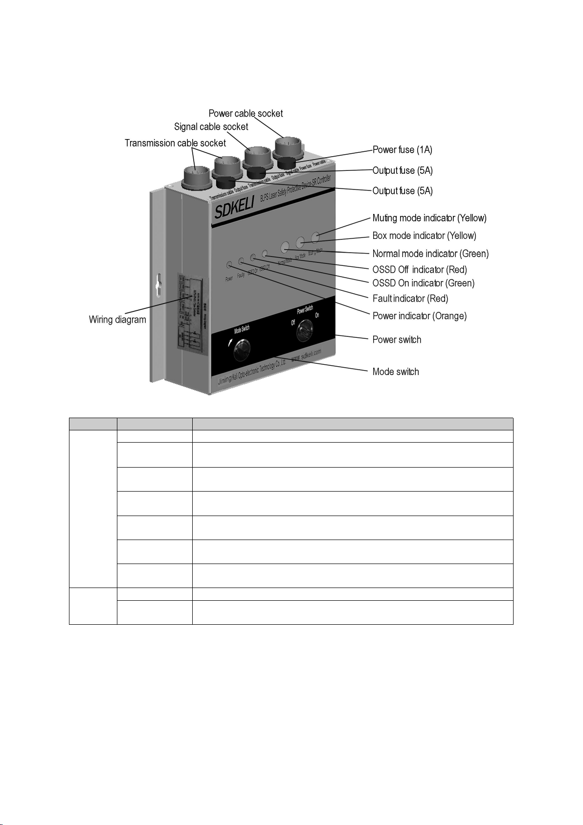
1.5.1 Appearance
Fig.1.6 Appearance of SR/SP controller
Name
Description
Indicator
Power
Yellow indicator light, when the power is turned on, the light is on,.
Fault
Red indicator light, when the system detects a fault, the light is on.
OSSD ON
Green indicator light, when the system output relay contact is on, the light
is on.
OSSD OFF
Red indicator light, when the system output relay contact is disconnected,
the light is on.
Normal mode
Green indicator light, when the controller is working in normal mode, the
light is on.
Box mode
Yellow indicator light, when the controller is working in box folding mode,
the light is on.
Muting mode
Yellow indicator light, when the controller is working in inhibit mode, the
light is on.
Switch
Power switch
System power control switch.
Mode switch
Rotate the key according to the indicated direction, and switch in turn in
normal mode-box folding mode-suppression mode-normal mode.

- 11 -
Fig.1.7 Appearance of ST controller
Number
Name
Description
1
Process
10 yellow indicator lights indicate the current program number. There are 10
processes in total. When the controller status is in a certain process, the
yellow indicator light of this process is on, and the other process lights are
off.
2
Shield
10 red indicator lights, indicating the shielding status of the corresponding
process.The red light is on, indicating that the corresponding process is in
the shielding state;The red light is off, indicating that the corresponding
process is in the normal protection state.
3
Shield 1~10
10 two-position key switches are used to select the shielding/normal
function of the corresponding process.
4
Sensor status
Green indicator light;
The green light is on, the sensor is normal;
The green light is off, and the sensor is shading.
5
Variable
speed signal
Red indicator light;
The red light is on, the variable speed signal is in the high-level active state,
and the bending machine is in the work advance (slow speed) state at this
time;
The red light is off, and the variable speed signal is in a low level state.
6
Output state
Green indicator light;
The green light is on, and the controller relay contact output is in the closed
state;
The green light is off, and the controller relay contact output is in the
disconnected state.
7
Reset
The self-reset button, when pressed, forces the controller to return to the
process 1 state.
8
Switch
System power control switch

- 12 -
1.5.2 Dimensions
Fig.1.8 Dimensions of SR/SP controller
Fig.1.9 Dimensions of ST controller
- 13 -
1.6. Cables
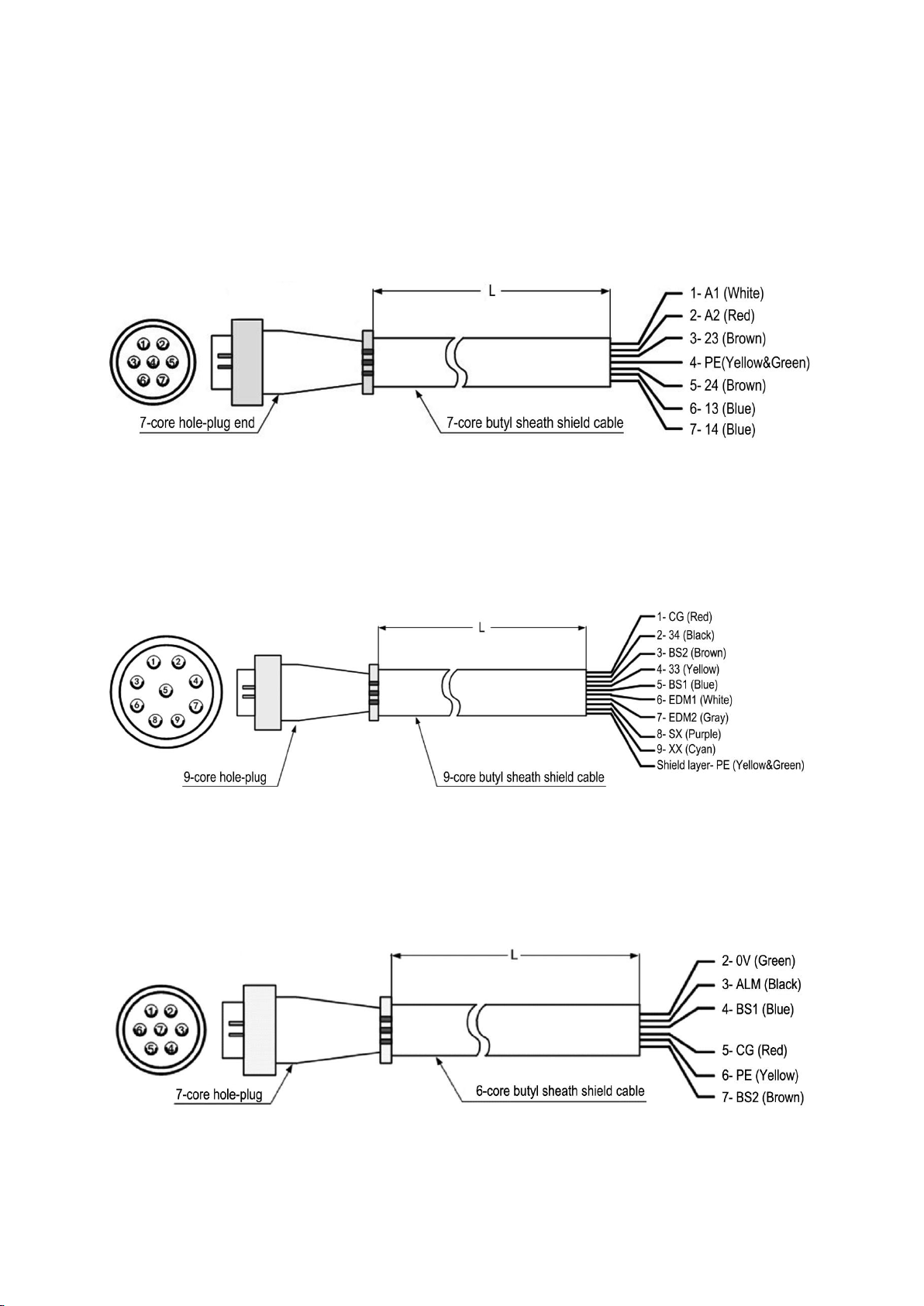
1.6.1 Power cable
Power cable is the 7-core butyl sheath shield cable with a 7-core hole-plug end connected to
the controller and each core at the other end of the cable is crimped with binding terminal to
connect to the bending machine. The number, color and function of the cores are shown as
follows:
Fig.1.10 Power cable
1.6.2 Signal cable
Equipped with signal cable for SR/SP controller
The signal line with SR / SP controller adopts 9-core butyl sheath shield cable, one end is
9-core hole-plug, which is connected with the controller, and the other end is connected with
each wire core crimping terminal, which is connected with the bending machine. The serial
number, color and function of each core are shown in the figure below:
Fig.1.11 Signal cable for SR/SP controller
Equipped with signal cable for ST controller
The signal line for ST controller is a 6-core shielded cable, one end is a 7-core aviation plug,
which is connected with the controller, and the other end is connected to the bending machine
by crimping terminals. The serial number, color and function of each core are shown in the
figure below:
Fig.1.12 Signal cable for ST controller
- 14 -
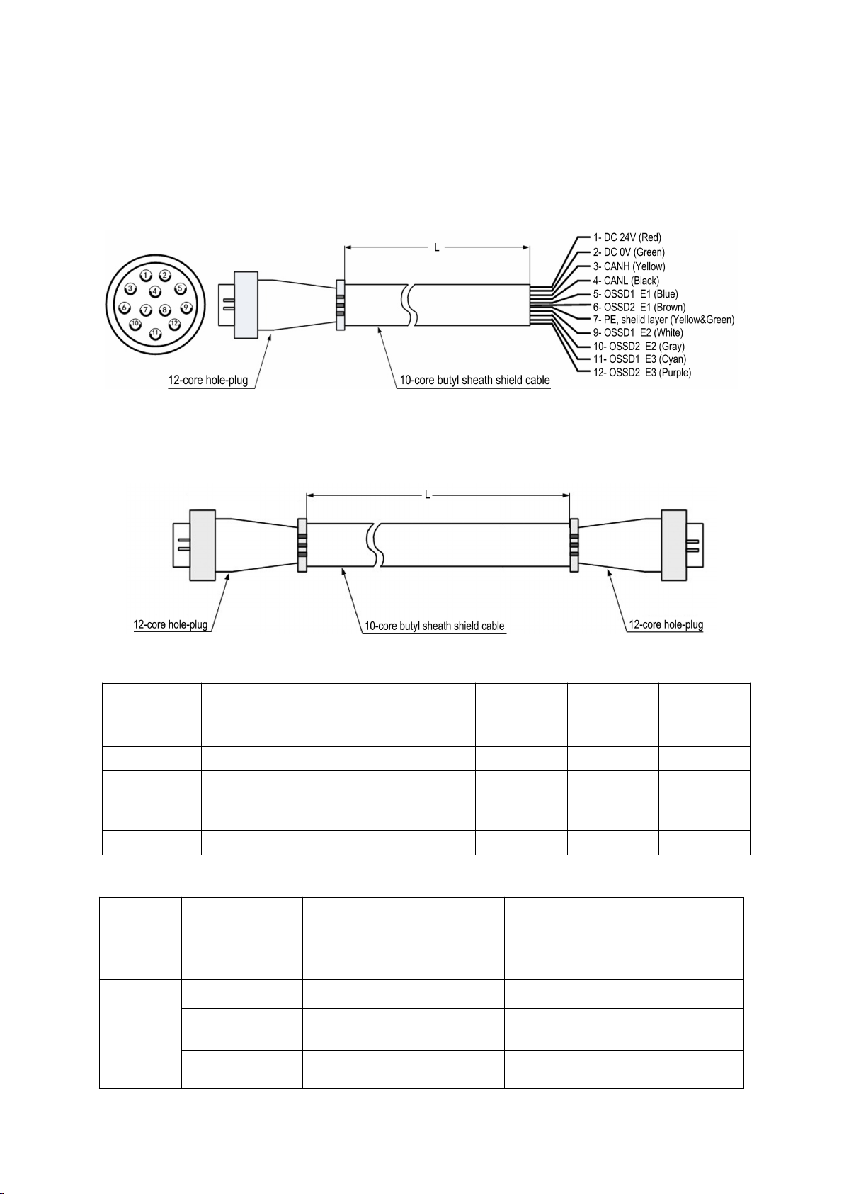
1.6.3 Transmission cable
Single-end cable
The single-ended transmission line uses a 10-core butyl sheath shield cable, one end is a
12-core hole-plug, which is connected to the sensor, and the other end is crimped to the
terminal with each core and connected to the bending machine. The serial number, color and
function of each core are as shown in the figure below:
Fig.1.13 Single-end cable
Double-end cable
Double-end cable is the 10-core butyl sheath shield cable with two 12-core hole-plugs at each
connected to the sensor. The number, color and function of the cores are shown as follows:
Fig.1.14 Double-end cable
Socket pin
1
2
3
4
5
6
Signal
definition
VCC
GND
CANH
CANL
OSSD1 (E1)
OSSD2(E1)
Wire color
Red
Green
Yellow
Black
Blue
Brown
Socket pin
7
8
9
10
11
12
Signal
definition
PE
-
OSSD1 (E2)
OSSD2(E2)
OSSD1 (E3)
OSSD2(E3)
Wire color
Yellow&Green
-
White
Gray
Cyan
Purple
Cable specifications list:
Usage
Name
Specifications
Number
Connecting devices
Standard
line length
Sensor
used alone
Single-end cable
CTBLX1D
2
Sensor to Bending
machine
5m&9m
Sensor
used with
SR / SP
controller
Double-end cable
CTBLX1S
2
Sensor to Controller
5m&9m
Power cable
CPSRX1X
1
Controller to Bending
machine
5m
Signal cable
CPSRX2X
1
Controller to Bending
machine
5m

- 15 -
Sensor
used with
ST
controller
Double-end cable
CTBLX1D
2
Sensor to Controller
5m&9m
Power cable
CPSRX1X
1
Controller to Bending
machine
5m
Signal cable
CPSTX2X
1
Controller to Bending
machine
5m
Note 1: the total length of two transmission lines of each set of products is not more than 40m, and the
cable length can be customized according to the actual demand.
Note 2: the power supply wire and signal wire used by SP controller are the same as SR type controller.
1.7. Mounting brackets
Fig.1.16 Dimensions of linear bracket
Fig.1.16 Dimensions of guide bracket

- 16 -
1.8. Technical parameters
Sensor technical parameters:
Security category
Safety type
Type 4(IEC 61496)PL e(ISO 13849)
Executive
standard
2006/42/EC (Machinery Directive) 2014/108/EU (EMC Directive)
IEC 61496-1 IEC 61496-2 ISO 13849-1
CCF
100
DCavg
99%
MTTF(Year)
95
MTTFD
(Year)
761
PFHD(1/h)
3.25 E-09
Optical characteristics
Light source
Class 1 laser product, 635nm wavelength
Detecting range
0~20m
Effective aperture angle
≤1.5mrad
Environmental characteristics
Ambient
temperature
Operation:-10℃~55℃(without frost and fog)
Storage:-30℃~70℃
Ambient
humidity
Operation:35%RH~85%RH
Storage: 35%RH~95%RH
Protection
level
IP65
Environmental
illuminance
Incandescent lamp:3000
Lux
Fluorescent lamp:3000
Lux
Sunlight: 10000 Lux
Homologous
light
interference
Interference light from the same design transmitter will not cause the BLPs to fail
Anti-vibration
ability
The frequency is 10-55hz, the amplitude is 0.35 ± 0.05mm, 20 times in X, y and Z
directions respectively
Impact
resistance
Acceleration 10g, pulse duration 16ms, 1000 times in X, y and Z directions
Electrical characteristics
Supply voltage
24V DC±20%
power consumption
≤3.5W
Current
consumption
Emitter
≤20 mA
Receiver
≤100 mA(Without load)
Response time
≤20ms(Complete machine, including controller)
Safety output(OSSD)
PNP output, each beam of detection light output two control signals
In on state, IOUT ≤ 100mA (6-way total ≤ 600mA), Vout ≥ vcc-2v
In off state, IOUT ≤ 1mA, Vout ≤ 2V
Function to prevent
mutual interference
Light interference avoidance algorithm

- 17 -
SR/SP controller technical parameters:
Project
Parameter
Ambient temperature
Operation:-10℃~55℃(without
frost and fog)
Storage:-40℃~70℃
Ambient humidity
Operation:35%RH~85%RH
Storage:35%RH~95%RH
Protection level
IP54
Dimensions
190×150×58mm
Supply voltage
AC100V~230V±10%,50/60Hz
DC24V±20%
Total power consumption
≤8.5W
Output form
Relay contact output
Output contact capacity
Contact capacity 5A, 250VAC/5A, DC24V
Start Time
<3s
Detection function
Real-time self-check
Protection circuit
The protection of overvoltage and overcurrent Output short circuit protection
ST controller technical parameters:
Project
Parameter
Ambient
temperature
Operation:-10℃~55℃(without frost and
fog)
Storage:-40℃~70℃
Ambient humidity
Operation:35%RH~85%RH
Storage:35%RH~95%RH
Protection level
IP54
Dimensions
195×180×82mm
Supply voltage
DC24V±20%
Total power
consumption
≤15W
Output form
OSSD1/OSSD2
Two-way relay normally open contact (main control output)
ALARM
PNP alarm output
Output contact
capacity
OSSD1/OSSD2
Contacts5A,250VAC/5A,DC24V
ALARM
Load current≤200mA
Response time
≤20ms
Insulation
resistance
>100MΩ
Dielectric strength
AC1500V,60S No breakdown or flashover
Relay life
≥100 million times

- 29 -
- 18 -
Section2 Function introduction
2.1 Input/Output interface circuit
2.1.1 Interface circuit of sensor
Fig.2.1 Interface circuit of sensor
Signal and wiring introduction:
Signal label
Meaning of signal
Wiring
DC24V
Anode of power supply
Connect with anode of power supply
DC0V
Cathode of power supply
Connect with cathode of power supply
PE
GND
Connecting to the ground
CANH/CANL
The communication interface between
emitter and receiver
Link CANH and CANL respectively
between emitter and receiver
OSSD1 E1
OSSD2 E1
Control output interface of E1, PNP
output, output high level voltage when
the sensor is on light-passing state
Two safety outputs
OSSD1 E2
OSSD2 E2
Control output interface of E2, PNP
output, output high level voltage when
the sensor is on light-passing state
Two safety outputs
OSSD1 E3
OSSD2 E3
Control output interface of E3, PNP
output, output high level voltage when
the sensor is on light-passing state
Two safety outputs

- 29 -
- 19 -
2.1.2 Interface circuit of controller
SR controller
Fig.2.2 Interface circuit of SR
Signal and wiring introduction:
Signal label
Meaning of signal
Wiring
A1/A2/PE
Power input
Connect to the right power supply
according to the rated voltage
CG
Reference high- level signal output of
the controller
Provide high-level voltage for external
relay contacts
BS1/BS2
Gearshift signal of the bender
Connect to the NO contacts of the relay
which controls the slow down stroke of
the bender
OSSDs
Output signal of the sensor
Connect to the controller
13/14,23/24
OSSD in the form of relay output
signal
Connect to the circuit which controls the
fast down stroke of the bender
Table of contents
Other SDKELI Safety Equipment manuals


