SDKELI LCSII User manual
LCSⅡ Light Curtain
Operation Manual
( 2022.01)
Jining KeLi Photoelectronic Industrial Co., Ltd.
Legislation and standards
LCS
Ⅱlight curtain complies with the following legislations and
standards:
EU legislations
Machinery Directive 2006/42/EC
EMC Directive 2014/30/EU
International Standards
IEC 61496-1, IEC 61496-2
ISO 13849-1
National Standards
GB/T 19436.1, GB/T 19436.2, GB 4584
Precautions on safety
The following special information may appear at any place in the
manual or on LCS
Ⅱ, as a warning of potential risk or promotion of
special attention to information about clarifying or simplifying certain
procedures.
This is the safety alert symbol. It is used to alert you to potential
personal injury hazards. Obey all safety messages that follow this
symbol to avoid possible injury or death.
WARNING
WARNNING indicates an actual or potential risk or health hazard.
They are designed to help you to prevent accidents. Read
carefully and follow the warnings!
CAUTION
CAUTION indicates the key information which, if not avoided, can
result in expected legal dispute, or equipment damage.
Read carefully and follow the cautions!
CAUTION
Thoroughly read this manual and understand the installation
procedures, operation check procedures, and maintenance
procedures before using the product.
LCS
Ⅱ
should only be installed, checked, and maintained by a
qualified person. A qualified person is defined as “a person or
persons who, by possession of a recognized degree or certicate
of professional training, or who, by extensive knowledge, training
and experience, has successfully demonstrated the ability to solve
problems relating to the subject matter and work” .
OSSDs must satisfy the following conditions:
Not short-circuited with 24V
The OSSDs should not be used with a current that is higher than
the rating.
Do not drop the product.
Dispose of the product in accordance with the relevant rules and
regulations of the country or area where the product is used.
The user should establish the rules and regulations for safe
operation and carry out them eectively.
Applications
LCS
Ⅱ
designed for industrial automation specially, the typical applications
are as follows: automated assembly production lines, industrial robots,
packaging equipment, automation equipment, welding lines, and so on.
LCS
Ⅱ
can only detect objects which intrude into the detection zone.
Detection zone is the rectangular area between the emitter and the
receiver, formed by protective height and operating range.
LCSII can onlycannot detect transparent and/or translucent objects.
The size of the guarded object must not be less than the detection
capability. Detection capability is the sensing function parameter limit
specied by the supplier that will cause actuation of the system.
1. System components
LCSII is composed of an emitter, a receiver and two transmission cables, as
shown in the following gure.
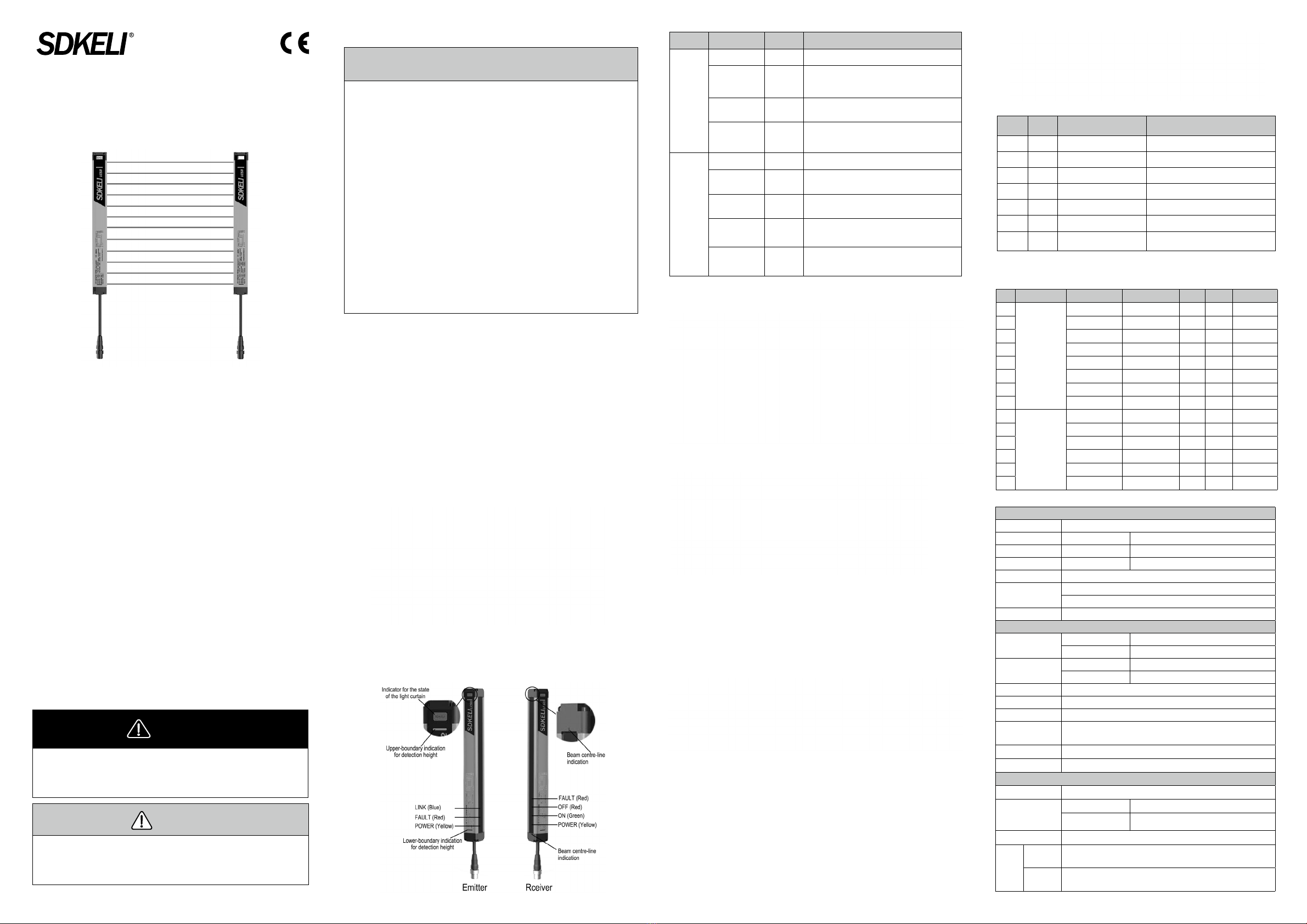
2. Appearance
LCSII is composed of emitter and receiver, using the outlet mode integrated
in the end cap, connecting to the external signals with high exible cable,
shown in the following gure.
LED Indicator Colour Description
Emitter
POWER Yellow Turns on while the power is on.
FAULT Red
Turns on when the system is in fault state or the
communication is wrong. The OSSDs output OFF-
state and the guarded machine can’t work.
LINK Blue Turns on while there is communication between
emitter and receiver.
End cap
indicator Red/Green
Display green when the OSSDs output ON-state,
display red when the OSSDs output OFF-state or
the system is in fault state.
Receiver
POWER Yellow Turns on while the power is on.
ON Green Turns on when the OSSDs output ON-state. The
guarded machine works.
OFF Red Turns on when the OSSDs output OFF-state and the
guarded machine can’t work.
FAULT Red
Turns on when the system is in fault state. The
OSSDs output OFF-state and the guarded machine
can’t work.
End cap
indicator Red/Green
Display green when the OSSDs output ON-state,
display red when the OSSDs output OFF-state or
the system is in fault state.
3. Specications
Specication of the system
Specication of emitter/receiver
4. Transmission cable
The transmission cable is used for signal transmission between the sensor
and the control circuit of the guarded machine. Transmission cable is
divided into standard cable and high exible cable, high exible cable can
be used in frequently moving occasions.
The standard length of transmission cable is 2m, 3m, 4m, and 5m.
The connection points are shown in the gure below.
Transmission cable is the 6-core butyl sheath shield cable, with the
waterproof plug at one end connected with the sensor and the other end
connected to the guarded machine.
If the standard transmission cable can not meet the requirements of the
use, the extension cable can be used to increase the length of transmission
cable. Extension cable is divided into standard cable and flexible cable,
high exible cable can be used in frequently moving occasions.
Extension cable is the 6-core butyl sheath shield cable, with the hole
seat at one end and the pin seat at the other end. The standard length of
transmission cable is 5m, 10m and 20m. The picture is as follows:
The number, color and function of the cores are shown in following table.
Pin
number
Signal
label Meaning of signal Wiring
1 Yellow CANH communication signal Connect CANH between emitter and receiver
2 Green Cathode of input DC24V Connect with cathode of input DC24V
3 Black NPN control output interface Control output interface 1
4 Blue CANL communication signal Connect CANL between emitter and receiver
5Red Anode of input DC24V Connect with anode of input DC24V
7 Brown PNP control output interface Control output interface 2
Yellow/
Green Shield layer Short circuited with the cathode of power
supply negative short and connect
Note: LCSII integrates NPN and PNP outputs together , while black wire is for NPN interface
and brown wire is for PNP interface.
The specications of transmission cable and extended cable are shown in the
following table.
No. Type Material code Specication Length Unit Remarks
1
Transmission
cable
CTL2XDC0001 CTL2X1D020C 2m Piece
2 CTL2XDC0002 CTL2X1D030C 3m Piece
3 CTL2XDC0003 CTL2X1D040C 4m Piece
4 CTL2XDC0004 CTL2X1D050C 5m Piece
5 CTL2XTC0001 CTL2X1T020C 2m Piece High exible
6 CTL2XTC0002 CTL2X1T030C 3m Piece High exible
7 CTL2XTC0003 CTL2X1T040C 4m Piece High exible
8 CTL2XTC0004 CTL2X1T050C 5m Piece High exible
9
Extension cable
CT6MXSC0003 CT6MX3S050C 5m Piece
10 CT6MXSC0004 CT6MX3S100C 10m Piece
11 CT6MXSC0005 CT6MX3S200C 20m Piece
12 CT6MXTC0001 CT6MX3T050C 5m Piece High exible
13 CT6MXTC0002 CT6MX3T100C 10m Piece High exible
14 CT6MXTC0003 CT6MX3T200C 20m Piece High exible
●
●
●
●
●
●
●
●
●
Precautions for safe use
5. Technical parameters
Optical characteristics
Light source Infrared LED (wavelength 850nm)
Beam spacing 20mm 40mm
Detection capability 30mm 50mm
No. of beams 8, 12, 16 … 96 4, 6, 8 … 48
Protective length 0 to 5m
Protective height 20mm beam spacing : 20 × (beam number -1) units : mm
40mm beam spacing : 40 × (beam number -1) + 20 units : mm
EAA < 5°
Environmental characteristics
Ambient
temperature
Operation -10 to 55℃ (non-condensing)
Storage -40 to 70℃
Ambient humidity Operation 35% to 85%RH
Storage 35% to 95%RH
Enclosure rating IP54
Ambient illumination 10000 Lux
EMC Meet the standard of Type4 light curtain
Vibration resistance 10 to 55Hz frequency range, 1 octave/min. sweep rate, 0.35mm + 0.05
amplitude, 20 sweeps per axis
Shock resistance 10g, 16 ms duration, 1000 bumps for each axis (applies to all 3 axes)
Dimensions 26.5×30×J mm(J- length of emitter/receiver)
Electrical characteristics
Supply voltage DC21.6V ~ 26.4 V
Consumption
current
Emitter ≤ 30mA
Receiver ≤ 80mA (No load); ≤ 300mA (200mA load
current)
Response time Vary with the number of beams, see the list of specications
Output
NPN Load current ≤ 200mA max, Output voltage ≤ 2V when OSSD is in ON-
state;Output voltage ≥ VCC-2V when OSSD is in OFF-state
PNP Load current ≤ 200mA max, Output voltage ≥ VCC-2V when OSSD is in
ON-state; Output voltage ≤ 2V when OSSD is in OFF-state

WARNING
Wiring when the power of LCSII is turned OFF.
Double or reinforced insulation must be applied between the
input/output interface and dangerous voltage, otherwise may
lead to electric shock.
Do not short-circuit OSSD to the power supply, otherwise the
OSSD is always ON.
The two OSSDs must not be short-circuited, otherwise
LCSII can not work in normal.
Do not connect each line of LCSII to a DC power supply higher
than 26.4V. Also, do not connect to an AC power supply.
Failure to do so may result in electric shock.
The power supply of LCSII should not be higher than
24V±10%, otherwise it may affect the stability of the light
curtain.
Change the cable without permission is strictly forbidden.
Properly perform the wiring after conrming the signal names
of all the terminals.
Be sure to route the LCSII cable separate from high-potential
power lines or through an exclusive conduit.
6. List of specications
Detection capability 30mm
Specication H(mm) J(mm) L(mm) C(mm) Response time(ms)
LCSIIA0820GPNT 140 190 500 260 < 10.1
LCSIIA1220GPNT 220 270 500 340 < 13.5
LCSIIA1620GPNT 300 350 750 420 < 16.8
LCSIIA2020GPNT 380 430 750 500 < 20.2
LCSIIA2420GPNT 460 510 750 580 < 23.5
LCSIIA2820GPNT 540 590 1000 660 < 26.9
LCSIIA3220GPNT 620 670 1000 740 < 30.3
LCSIIA3620GPNT 700 750 1000 820 < 33.6
LCSIIA4020GPNT 780 830 1200 900 < 37.0
LCSIIA4420GPNT 860 910 1200 980 < 40.4
LCSIIA4820GPNT 940 990 1200 1060 < 43.7
LCSIIA5220GPNT 1020 1070 1500 1140 < 47.1
LCSIIA5620GPNT 1100 1150 1500 1220 < 50.4
LCSIIA6020GPNT 1180 1230 1500 1300 < 53.8
LCSIIA6420GPNT 1260 1310 1500 1380 < 57.2
LCSIIA6820GPNT 1340 1390 1750 1460 < 60.5
LCSIIA7220GPNT 1420 1470 1750 1540 < 63.9
LCSIIA7620GPNT 1500 1550 1750 1620 < 67.3
LCSIIA8020GPNT 1580 1630 2000 1700 < 70.6
LCSIIA8420GPNT 1660 1710 2000 1780 < 74.0
LCSIIA8820GPNT 1740 1790 2000 1860 < 77.3
LCSIIA9220GPNT 1820 1870 1940 < 80.7
LCSIIA9620GPNT 1900 1950 2020 < 84.1
Detection capability 50mm
Specication H(mm) J(mm) L(mm) C(mm) Response time(ms)
LCSIIA0440GPNT 140 190 500 260 < 8.4
LCSIIA0640GPNT 220 270 500 340 < 10.1
LCSIIA0840GPNT 300 350 750 420 < 11.8
LCSIIA1040GPNT 380 430 750 500 < 13.5
LCSIIA1240GPNT 460 510 750 580 < 15.1
LCSIIA1440GPNT 540 590 1000 660 < 16.8
LCSIIA1640GPNT 620 670 1000 740 < 18.5
LCSIIA1840GPNT 700 750 1000 820 < 20.2
LCSIIA2040GPNT 780 830 1200 900 < 21.9
LCSIIA2240GPNT 860 910 1200 980 < 23.5
LCSIIA2440GPNT 940 990 1200 1060 < 25.2
LCSIIA2640GPNT 1020 1070 1500 1140 < 26.9
LCSIIA2840GPNT 1100 1150 1500 1220 < 28.6
LCSIIA3040GPNT 1180 1230 1500 1300 < 30.3
LCSIIA3240GPNT 1260 1310 1500 1380 < 31.9
LCSIIA3440GPNT 1340 1390 1750 1460 < 33.6
LCSIIA3640GPNT 1420 1470 1750 1540 < 35.3
LCSIIA3840GPNT 1500 1550 1750 1620 < 37.0
LCSIIA4040GPNT 1580 1630 2000 1700 < 38.7
LCSIIA4240GPNT 1660 1710 2000 1780 < 40.4
LCSIIA4440GPNT 1740 1790 2000 1860 < 42.0
LCSIIA4640GPNT 1820 1870 1940 < 43.7
LCSIIA4840GPNT 1900 1950 2020 < 45.4
7. Mounting bracket dimensions
ZC-bracket L-bracket
8. Installation
8.1. ZC Installation(ZC)
ZC Installation(ZC)— Common front mounting
ZC Installation(ZC)— Common side mounting
8.2.T-groove Installation (TC)
9. Wiring
LCSII adopts DC24V power supply and outputs transistor control
signals directly . The output can provide one channel of PNP and one
channel of NPN. Wiring is as shown in the figure below, where the
control signal lines (brown and black) of the emitter should be left
oating.
●
●
●
●
●
●
●
●
●
H-
protective height,J-length of emitter/receiver,L-length of steel pipe,C-length of scatter shield
8.3.
Scatter shield mounting (FZC)
Scatter shield front mounting (FZ)Scatter shield side mounting (FC)
8.4.
Scatter shield pipe mounting (GF)
This manual suits for next models
46
Other SDKELI Safety Equipment manuals


Popular Safety Equipment manuals by other brands

Lanex
Lanex PB-20 instruction manual

SKYLOTEC
SKYLOTEC ANCHOR ROPES Instructions for use

Besto
Besto Buoyancy Aid 50N Instructions for use

TEUFELBERGER
TEUFELBERGER NODUS Manufacturer's information and instructions for use

Troy Lee Designs
Troy Lee Designs Tbone Product owners manual

Innova
Innova Xtirpa Instruction and safety manual

bolle SAFETY
bolle SAFETY B810 quick start guide

SHENZHEN FANHAI SANJIANG ELECTRONICS
SHENZHEN FANHAI SANJIANG ELECTRONICS A9060T instruction manual

Hiltron security
Hiltron security POWER8E Installation and use manual

Salewa
Salewa MTN SPIKE user manual

Hatco
Hatco B-950P installation guide

Sitec
Sitec TX MATIC operating manual


