SDR-Kits DG8SAQ VNWA 3 User manual

SDR-Kits® VNWA 3SE 2 Port Upgrade - Assembly Information v0.2 © 2020 by SDR-Kits® Page 1of 6
SDR-Kits® Office 11, Hampton Park West, Melksham, Wilts, SN12 6LH United Kingdom
1 i-Cal: Automatic Calibration
DG8SAQ VNWA 3SE 2 Port VNWA upgrade Kit assembly
1. Introduction
Thank you for purchasing the VNWA 3SE 2 Port VNWA upgrade kit either in SMA or N-
Connector version. This leaflet contains additional user information how to perform the
hardware upgrade of a VNWA 3E to a VNWA 3SE.
This upgrade requires that the basic VNWA 3E, is fitted with the USB Expansion PCB and is in
good usable condition.
If you have a VNWA 3 then an upgrade to VNWA 3SE is possible by but first you have to fit the
VNWA Expansion board (stocked by SDR-Kits) and perform an upgrade to a VNWA 3E.
The VNWA 3 expansion board comes with a detailed upgrade manual. For all other questions it
is recommended to consult the VNWA help file by pressing the Help tab in the VNWA software.
A pdf version of this helpfile can be downloaded from:
http://www.sdr-kits.net/documents/VNWA_HELP.pdf
2. Important information
The design of the VNWA 3E and VNWA 3SE is copyright by Thomas Baier DG8SAQ and SDR-
Kits®. Reverse Engineering of the VNWA design is strictly forbidden. SDR-Kits® and the SDR-
Kits Logo are Registered Trademarks. All rights reserved.
from beginner to very experienced, this is the first place to look first if you have a question.
3. Preparation:
The VNWA 3SE upgrade kit consists of the following
1 pc assembled VNWA 3SE SMA or N upgrade assembly as ordered.
This assembled module is fitted with the S-Parameter PCB and 2 semirigid
cables and is already fitted into a new longer 2-part enclosure complete with 4
rubber feet and (3) EMC strips inside the top enclosure cover as shown.
1 pc RJ12 to RJ12 cable
8 pcs M3x8mm hex c/s screws

SDR-Kits® VNWA 3SE 2 Port Upgrade - Assembly Information v0.2 © 2020 by SDR-Kits® Page 2of 6
4 pc M3x6mm hex c/s screws
1 pc 2mm hex tool
1 pc SDR-Kits SMA tool to fit 5mm, 5.5mm, 6mm and 8mm nuts
1 pc double-sided adhesive foam tape
4. Step by step upgrade
4.1 Prepare the VNWA 3E by removing the VNWA 3E bottom cover. Remove the (4)
hex screws using the 2mm hex key supplied. If one of the hex screws is damaged, then
a T5 torque screw should offer sufficient grip to unscrew without the need to drill out the
damaged screw. You need to save (4) of the (8) enclosure screws as these will be
required for fitting the VNWA into the new enclosure.
4.2 Inspect the VNWA 3E chassis to determine if two slots are already present, as
shown in the pictures below. If these slots are not present, then two slots 8mm x 2.5mm
will need to be made in the brass chassis as shown below.
There are two options: one is filing the slots with a suitable key-file and alternative is to
use a sheet metal nibbling tool.
Red arrow in above image shows location slot and filing method to avoid PCB contamination
4.3 Filing the 2 slots, Caution, be careful that filing debris does not get deposited
anywhere on the inside of the PCB. This can be prevented by;
4.3.1 Placing the Plastic covers over the VNWA front connectors
4.3.2 Use masking tape to cover the holes on the rear of the VNWA
4.3.3 Place the chassis partly on a piece wood or other and file upwards so the
metal filings fall down as shown below.
Location of front slot of VNWA 3E and showing method of filing board avoiding contamination

SDR-Kits® VNWA 3SE 2 Port Upgrade - Assembly Information v0.2 © 2020 by SDR-Kits® Page 3of 6
4.4 Alternatively using a suitable sheet nibbler tool (available from SDR-Kits).
The nibbler tool does the job easily in less than 10 seconds without any mess.
See red arrows in above image for location of the slots
4.5 If it is deemed necessary to remove the expansion board then this can be done by
first de-soldering the connecting wire link from the expansion PCB to the center pin of the
SMA clock connector. Then loosen the (3) M2.5 screws with felt washers accessible
from the top of the PCB several turns. When all the screws have been loosened with the
screwdriver push the screws down, which will push the expansion board out of the
bottom connectors. Next remove the screws and felt washers completely and gently
unplug the expansion board. Refitting is a reversal of the above steps.
4.6 After the slots have been made, remove the remaining VNWA 3E enclosure cover
and save the (4) M3 screws. The VNWA 3E is now ready for fitting into the VNWA 3SE
chassis. Protect the sharp edges of the two slots using small strips cut from the double-
sided tape provided, plug-in the RJ12 cable into the front RJ12 socket and position the
cable as shown in the picture below. Make sure that cable is protected from sharp edges
by the tape supplied.
Fitting of VNWA inside enclosure. Either RG405 or RG402 semirigid cables will be
supplied with no difference in performance. RG405 are thinner but easier to fit.

SDR-Kits® VNWA 3SE 2 Port Upgrade - Assembly Information v0.2 © 2020 by SDR-Kits® Page 4of 6
4.7 Place the VNWA 3E assembly loosely into the upgrade Chassis and the bottom
enclosure cover as shown in previous picture. CAREFULLY align the 2 pre-formed
semirigid cables by hand so they mate exactly with the (2) SMA connectors on the front
of the VNWA. Now hand- tighten the screws of the two SMA cables in turn till the
connectors are fully screwed home. Adjust the semirigid cables as you go along by hand
to avoid any undue tension.
4.8 Next tighten the SMA semirigid connectors to the front SMA connectors of the
VNWA 3E to a torque of 0.45 Newton meter N-m = 4 lb-inch The SMA connectors
already screwed into the VNWA 3SE switch printed circuit board are already tightened to
spec prior shipping and should not need adjusting.
4.9 Next step is to reposition the VNWA 3E module so the (4) holes on the side,
marked with red arrows in the above image, are aligned. Gently slide the VNWA module
forward, whilst adjusting the semirigid cables by hand until the holes are aligned and fit
(2) M3 x 6mm c/s screws to to the 2 top holes. (These screws are recovered previously
from removing the VNWA 3 enclosure covers). Next lift the VNWA3 SE chassis from the
bottom cover and fit the remaining (2) M3 x 6mm c/s hex screws.
4.10 Final Assembly: Plug the RJ12 cable into the VNWA 3E socket at the back. Do a
final inspection on position of the RJ12 cable through the 2 slots to ensure it is not
pinched. Next fit into the bottom VNWA 3SE enclosure and screw together using (4)
M3x8mm c/s hex screws supplied.
Align the three EMC strips inside the top cover with the VNWA 3SE front and the VNWA
3E front and rear panel and fit using the (4) remaining screws supplied in the kit.
End of assembly
SDR-Kits® VNWA 3SE 2 Port Upgrade - Assembly Information v0.2 © 2020 by SDR-Kits® Page 5of 6
5. Software configuration for VNWA 3SE 2-Port VNWA
This chapter assumes that the VNWA 3E software and driver installation has been done
and the VNWA application configuration has been done as described in the “VNWA 3E
Getting Started Manual” supplied with the VNWA3E o can be downloaded from:
https://www.sdr-kits.net/documents/VNWA_W10_W8_W7_Installation.pdf
a) Start VNWA software application as usual
b) Go to tab Options and select Setup
c) Click on Tab USB Settings and click on Test USB Interface. If the result is not “Test
passed without errors”, check that the VNWA license code is correctly entered (see
HELP file if necessary).
d) Click on tab Audio settings and click on Auto-Setup Audio Devices. This
will configure the 2 audio codecs correctly
Configuring VNWA 3SE 2-Port functionality for the first time on a VNWA:
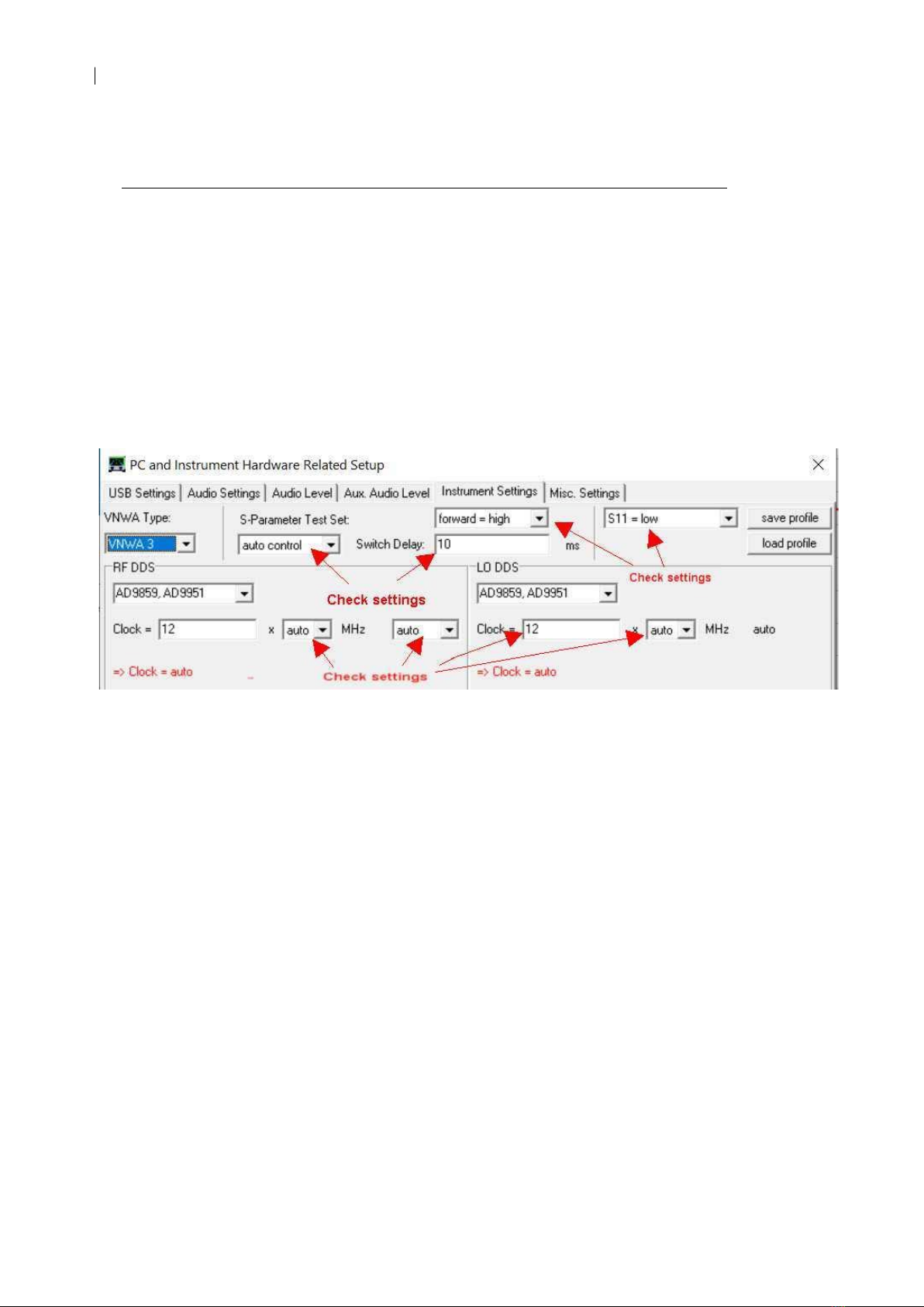
e) Click on tab Instrument Settings - the following window should be displayed:
f) Before the upgrade to the VNWA 3SE, the field S-Parameter Test Set is set to none.
For the VNWA 3SE with 2-Port operation, this field must be set auto control. You can
specify manual control if required. Check and set the other fields as shown above.
These settings are stored inside the VNWA hardware; thus the setting will be correct
when the user launches the VNWA application with the VNWA 3SE connected.
Note: A 2-Port VNWA will only switch to Port 2 when setup to measure S12 and S22 data.
SDR-Kits® VNWA 3SE 2 Port Upgrade - Assembly Information v0.2 © 2020 by SDR-Kits® Page 6of 6
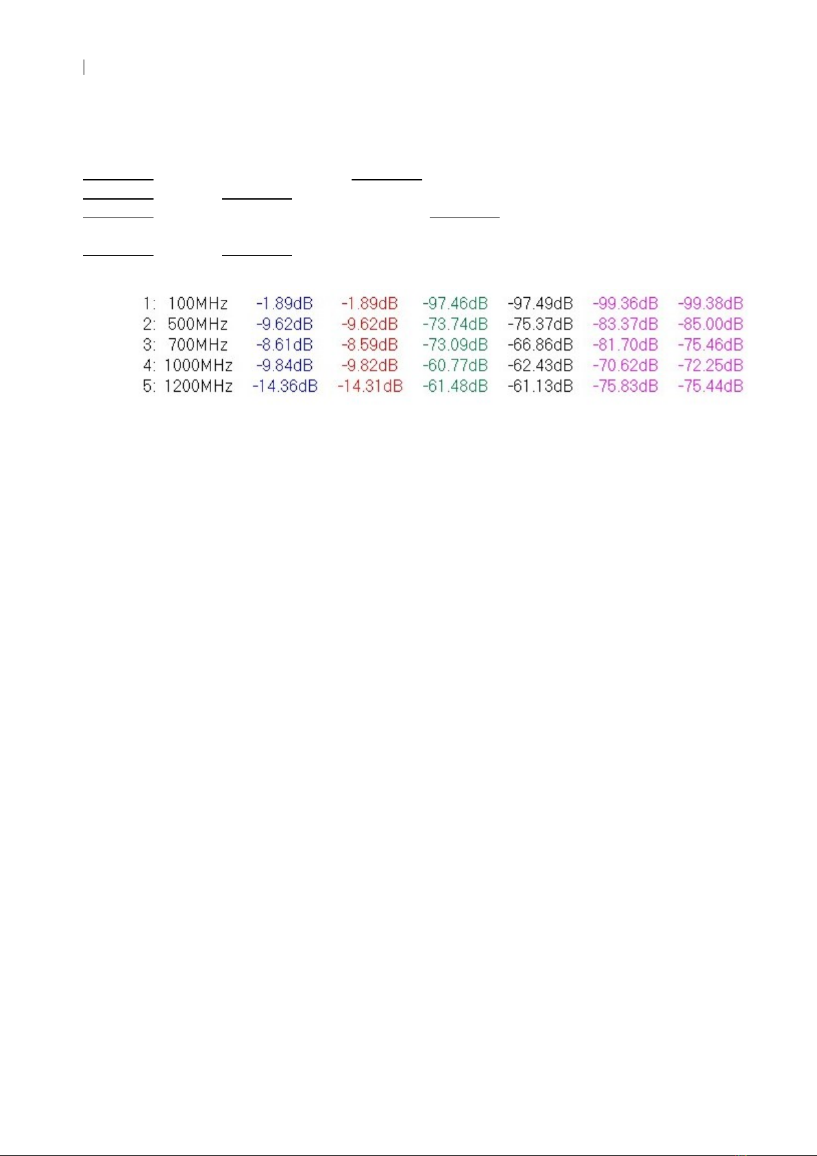
6. VNWA 3SE Commissioning Test (done at factory)
Every VNWA 3SE is supplied with a commissioning graph showing the measured
performance at various frequencies. All tests are done WITHOUT any calibration because
calibration obscures hardware problems. The meaning of the measurements is as follows:
Column 1 = Measurement number, Column 2 = Frequency of measurement.
Column 3 = S21 & Column 4 = S12 with RG223 cable connected between Port 1 and Port 2.
Column 5 = Port 1: Dynamic Range (DR S21): Column 6 = Port 2: Dynamic Range
(DR S12)
Column 7 = S21 & Column 8 = S12 measurement of noise floor with Open connectors
end of document
Other manuals for DG8SAQ VNWA 3
4
Table of contents
Other SDR-Kits Measuring Instrument manuals


