Knauer K-7400S Operating instructions

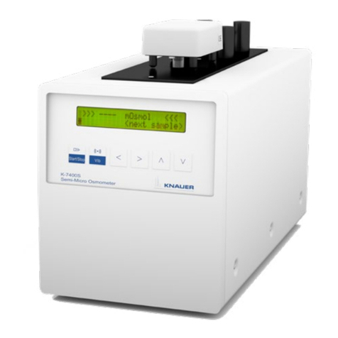
Semi-Micro Osmometer K-7400S
Service instructions
Document Number: V6700
Document no. VSM-012

Note: For your own safety, read the instructions and follow the
warnings and safety information on the device and in the instructions.
Keep the instructions for future reference.
Phone: +49 30 809727-111 (9-17h, Central European Time)
Fax: +49 30 8015010
E-mail: support@knauer.net
Languages: German, English
KNAUER Wissenschaftliche Geräte GmbH
Hegauer Weg 38
14163 Berlin
Germany
Phone: +49 30 809727-0
Fax: +49 30 8015010
Internet: www.knauer.net
E-mail: info@knauer.net
Document number: VSM-012
Version number: 2.1
Release date: October 14, 2022
Original edition
This document contains confidential information and may not be
reproduced without written consent of KNAUER Wissenschaftliche
Geräte GmbH.
© KNAUER Wissenschaftliche Geräte GmbH 2022
All rights reserved.
KNAUER Technical
Support:
Publisher:
Version information:
The information in this document is subject
to change without prior notice.
For latest version of the instructions, check our website:
www.knauer.net/en/partner-area/Service-manuals.
Legal information

Semi-Micro Osmometer K-7400S Service instructions , VSM-012
Table of contents
1. Important safety notes ................................................................1
1.1 Definition of personal or material damage ....................................2
1.2 Service request form and decontaminationreport .............................2
1.3 Symbols and Signs. . . . . . . . . . . . . . . . . . . . . . . . . . . . . . . . . . . . . . . . . . . . . . . . . . . . . . . . . 3
2. Overview ...........................................................................4
3. Replacement.........................................................................5
3.1 Housing ..................................................................5
3.2 Cooling block .............................................................6
3.3 Fan ......................................................................7
3.4 Display...................................................................7
3.5 Power supply .............................................................9
3.6 Mainboard...............................................................10
3.7 Battery of the mainboard ..................................................10
4. Adjustments ........................................................................11
4.1 Checking the performance of the coolingblock ..............................11
4.2 Calibrating the cooling block ..............................................11
4.3 Inserting the adapter into the coolingcavity .................................13
4.4 Setting the temperature of the cooling cavity.................................14
5. Firmware installation.................................................................15
5.1 Windows serial downloader program .......................................15
5.2 Hyper terminal program ...................................................18
6. Troubleshooting.....................................................................21
6.1 Error messages...........................................................21
7. Tips and Tricks ........................................................................22
7.1 Installation...............................................................22
7.2 General handling .........................................................22
7.3 Calibration...............................................................22
8. Spare Parts .........................................................................23

1
Semi-Micro Osmometer K-7400S Service instructions , VSM-012
1. Important safety notes
Only use the device for applications that fall within the range of the inten-
ded use. Otherwise, the protective and safety equipment of the device
could fail.
The service manual is an addition to the existing user manual; it includes all
work that requires the installation of certain components or the opening of
a device‘s housing.
This service manual is intended for the professional service technician
group as follow:
KNAUER service technicians
Service technicians authorized by KNAUER with a certificate
The following knowledge is required:
Good command of English to be able to use the English-language ser-
vice software and online help.
Participation during an installation of a device or a training by the com-
pany KNAUER or an authorized company.
If you do not belong to one of these professional groups, under no cir-
cumstances perform the work described in this manual. In this case,
contact your superior.
Observe the following:
All safety instructions in the maintenance manual
All safety instructions in the user manual
The environmental, installation, and connection specifications in the
user manual
Only use spare parts, tools and cleaning agents recommended or pre-
scribed by KNAUER.
When working with the device, take measures according to lab regulations
and wear protective clothing:
Safety glasses with side protection
Protective gloves
Lab coat
The warranty seal is a security label which indicates if any opening on
instrument has occurred. Most KNAUER products are sold with the blue
seal on the rear side to confirm that KNAUER was the last who took care of
the instrument. An authorized service technician should order and use the
warranty seal in orange color after opening the instrument (Order. no.
V0602).
Checking inten-
ded use
Who may per-
form repairs?
What has to be
taken into
account?
Safety
equipment
Warranty seal

2 Important safety notes
Semi-Micro Osmometer K-7400S Service instructions , VSM-012
1.1 Definition of personal or material damage
Possible dangers related to the device are distinguished in personal and
material damages in this service manual.
Symbol Meaning
Lethal injuries will occur.
Serious or moderate injuries can
occur.
Minor injuries can occur.
Device defects can occur.
Decontamination
Contamination of devices with toxic, infectious or radioactive substances
pose hazards for all persons during operation, repair, sale, and disposal
of a device.
Life-threatening injuries
Health danger if getting in contact with toxic, infectious or radio-active
substances.
Before disposing of the device or sending it away for repair, you are
required to decontaminate the device in a technically correct manner.
All contaminated devices have to be properly decontaminated by a spe-
cialized company or the operating company before they can be recom-
missioned, repaired, sold, or disposed of. All materials or fluids used for
decontamination have to be collected separately and disposed of pro-
perly.
1.2 Service request form and decontamina-
tionreport
Devices which are shipped without the completed document “Service
request form and decontamination report” will not be repaired. If you
would like to return a device to KNAUER, make sure to enclose the com-
pleted document: www.knauer.net/servicerequest

3 Important safety notes
Semi-Micro Osmometer K-7400S Service instructions , VSM-012
1.3 Symbols and Signs
The following symbols and signs can be found on the device, in the
chromatography software or in the service manual:
Symbol Meaning
Warning signs High voltage hazard!
Electric shock hazard!
Danger caused by potentially toxic sub-
stances!
Electrostatic discharge hazard, damages to
system, device, or components can occur.
General warning sign, moderate to minimal
injuries may occur. Damage to system,
device, or certain components is also possi-
ble.
Leak hazard, damage to device can occur.
Note the maximum weight limit, e.g. 0.5 kg!
CE mark A device or system marked with CE fulfills the
product specific requirements of European
directives. This is confirmed in a Declaration
of Conformity.
Testing seals in Canada and the USA at
nationally recognized testing centers (NRTL).
The certified device or system has success-
fully passed the quality and security tests.
The warranty seal is a security label which
indicates if any opening on instrument has
occurred. Most KNAUER products are sold
with the blue seal on the rear side to confirm
that KNAUER was the last who took care of
the instrument. An authorized service techni-
cian should order and use the warranty seal
in orange color after opening the instrument
(order no. V0602).

4
Semi-Micro Osmometer K-7400S Service instructions , VSM-012
2. Overview
A freezing point osmometer is capable of determining the osmolality of
aqueous solutions. The technique uses the fact that osmotically active
compounds depress the freezing point of a solution compared to pure
solvent. This phenomenon is called freezing point depression and is
independent of the nature, size or shape of particles.
The KNAUER freezing point osmometer is a simple, robust and easy to
maintain instrument with following features:
Automatic measurement process
Sample volume between 50 µL and 150µL (plastic measuring head)
Two or three-point calibration
Executable with EuroOsmo7400 software
Data output via printer
Legend
1 Measuring head
2 LCD Display
3 Keypad
4 RS-232 connector
5 Measuring head connector
6 Fan
7 Power switch
8 Power connector
Note: The glass version of measuring head is discontinued and replaced
by plastic version.

5
Semi-Micro Osmometer K-7400S Service instructions , VSM-012
3. Replacement
3.1 Housing
The device has been switched o.
Screwdriver
Process Figure
1. Unplug the main power and
measuring head cable.
2. Place the measuring head
aside and take care to not
damage thermistor or
stirring wire.
3. Loosen three screws on each
side of device 1and remo-
ve the housing backwards.
To mount the housing, proceed in reverse order.
Device defect
The housing oers protection from electrical voltage which is build
inside the device.
Before putting the device into operation, install the housing
completely.
Prerequisites
Tools
Electric shock
Danger of electric shock from voltage-carrying parts inside the device.
The housing serves as a protective cover against voltages inside the
device.
Switch the device o before opening the device.
Pull the power plug.

6 Replacement
Semi-Micro Osmometer K-7400S Service instructions , VSM-012
3.2 Cooling block
The device has been switched o.
The measuring head cable and power cable have been removed.
The housing has been removed (see chap. 3.1).
Screwdriver
Process Figure
1. Remove all cooling block
cables 1from the main
board.
2. Marking the cables before
unplugging is highly recom-
mended.
3. Loosen two screws 2on
both sides of cooling block
holder.
1. Remove the cooling block
upwards.
To mount the cooling block, proceed in reverse order.
Practical Tip The cooling block has to be adjusted/calibrated after the replacement.
The adjustment procedure will be described later in adjustments sec-
tion.
Prerequisites
Tools

7 Replacement
Semi-Micro Osmometer K-7400S Service instructions , VSM-012
3.3 Fan
The device has been switched o.
The measuring head cable and power cable have been removed.
The housing has been removed (see chap. 3.1).
Screwdriver
Process Figure
1. Disconnect the fan cable 1
from the mainboard.
2. Loosen the 4 outermost
screws of the rear plate and
pull it backward.
3. Loosen two diagonally
screws 2on the fan.
4. Remove the fan.
To mount the fan, proceed in reverse order.
3.4 Display
The measuring head cable and the power cable have been removed.
The housing has been removed (see chap. 3.1).
Screwdriver
Process Figure
1. Unplug the grey display
cable 1from the main-
board.
2. By unscrewing the screws
holding the display (see next
figure), remove it backwards.
Prerequisites
Tools
Prerequisites
Tools

8 Replacement
Semi-Micro Osmometer K-7400S Service instructions , VSM-012
Process Figure
3. Notice the installation order
of screws and rings.
1 Screw
2 Metal disk
3 Spacer sleeve
4 Paper disk
To mount the display, proceed in reverse order.

9 Replacement
Semi-Micro Osmometer K-7400S Service instructions , VSM-012
3.5 Power supply
The device has been switched o.
The power cable, the housing (see chap. 3.1) and the rear plate
(see chap. 3.3) have been removed.
Screwdriver
Process Figure
1. Loosen the keypad 1and
display 2cables from
mainboard.
2. Lay the device on one side.
3. Loosen the four screws 3on
the base plate.
4. Detach the housing from the
block carefully. On the
bottom of the block you will
find the power supply.
5. Unplug the ground cable 4,
the power input 5and the
connector to the mainboard
6.
6. Unscrew the four screws on
power supply 7.
7. Remove the power supply.
To mount the power supply, proceed in reverse order.
Prerequisites
Tools

10 Replacement
Semi-Micro Osmometer K-7400S Service instructions , VSM-012
3.6 Mainboard
The device has been switched o.
The power cable and housing have been removed (see chap. 3.1).
Screwdriver
Process Figure
1. Unscrew the four screws of
the cooling block (see chap.
3.2) and slide the block a
little bit forward to make
more space for moving the
mainboard.
2. Remove all cables from the
mainboard. Marking the
cables before removal is
highly recommended.
3. Loosen six screws 1on
mainboard.
4. Remove the mainboard
upwards.
To mount the main board, proceed in reverse order.
3.7 Battery of the mainboard
The device has been switched o.
The power cable and housing have been removed (see chap. 3.1).
Small slotted screwdriver (e.g. sice 2 mm)
Process Figure
1. In order to remove the
battery 1out of the battery
holder use the slotted
screwdriver.
2. Place the screwdriver next to
the battery clamp and push
the screwdriver gently under
the battery. Make sure not to
bend the clamp.
3. The battery will move for-
ward out of the holder.
4. Remove the battery.
To insert the battery of the main board, proceed in reverse order.
Prerequisites
Tools
Prerequisites
Tools
1

11
Semi-Micro Osmometer K-7400S Service instructions , VSM-012
4. Adjustments
4.1 Checking the performance of the
coolingblock
Deviation in measurement results and non frozen samples could be the
sign of a faulty cooling block. To ensure the functionality, check the perfor-
mance of the cooling block and, if necessary, readjust the temperature.
The housing has been removed.
Screw driver
Process Figure
1. Remove the heating cable 1
from main board ( -).
2. Switch the device on.
3. Monitor the cooler tempera-
ture from TEMP menu.
4. It must go down to less than
-30°C within 7min.
5. Otherwise, the block is faulty
and has to be replaced.
1
4.2 Calibrating the cooling block
The measuring head has been removed.
Distilled water
External calibrated thermometer (as reference device).
Process Figure
1. The device has to be swit-
ched on in service mode.
2. Switch the device on.
3. After the startup screen has
appeared, press the
up-down-up arrow keys
quickly.
4. Device is in service mode.
Prerequisites
Required Tools
Prerequisites
Required Tools

12 Adjustments
Semi-Micro Osmometer K-7400S Service instructions , VSM-012
Process Figure
5. Fill water up to the edge of
the copper ring 1.
6. Immerse an external ther-
mometer in block cavity
which is filled with water.
7. Go to the C. C
menu and press
button.
8. The unit cools down to
-15°C.
9. Compare the temperatures
on external thermometer
and device and then enter
the measured temperature
from thermometer on
mentioned menu and press
start button again to apply
the correction.
10. The final value will be shown
after the correction is
applied.
11. Press button to store
the value on main board.
If the adjustment process does not show the desired result, repeat steps
7-11. Deviations up to ± 0.2°C are acceptable.
After completing the adjustment process the water has to be removed
and the cooling block cavity has to be dried.

13 Adjustments
Semi-Micro Osmometer K-7400S Service instructions , VSM-012
4.3 Inserting the adapter into the cooling
cavity
For using the measuring head for plastic vials (A0840-2) on the osmometer
K7400 (A3709, A3709-1, A3709-2), a cooling cavity adapter is required.
The adapter allows optimum heat transfer between measuring head and
cooling block.
Note: The adapter is pre installed on K-7400S.
1Cooling cavity adapter (article no. G1770)
2Adapter tool (article no. W0225)
Instead of adapter tool (W0225) a M5x55 threading screw could be used.
The adapter edges are thin and easy to bend. Inserting and extraction
must be done carefully.
Process Figure
1. Orient the adapter 1with
the O-ring pointing to the
outside.
2. Screw the adapter tool 2in
adapter carefully, until the
threading lies flat with the
ending of the adapter.
3. Guide the adapter carefully
into the cooling block cavity
3and press in gently.
4. Unscrew the adapter tool
from the adapter.
Note: To make sure that the adapter fits correctly, push the plastic vial
in carefully. To remove the adapter use the tool and proceed in reverse
order.
Required Tools

14 Adjustments
Semi-Micro Osmometer K-7400S Service instructions , VSM-012
4.4 Setting the temperature of the cooling
cavity
The temperature setting for plastic measuring head A0840-2, is dierent
compared to former one, A0840-1.
The recommended temperature setting which must be set in C menu,
on osmometer display is:
: -8°C
C : -16°C
If the mentioned setting does not meet the measurements need, due to
the concentration of sample, performance of cooling block or any other
reason, proceed as described in troubleshooting section by changing the
temperatures.
By insertion of the adapter in cooling cavity, the measuring head is slighty
raised in comparison to the measuring head for glass vials. The feet of the
measuring head do not need to rest on the device. This aspect does not
aect the measurement results.
Practical tip

15
Semi-Micro Osmometer K-7400S Service instructions , VSM-012
5. Firmware installation
The measuring head and housing have been removed
Windows Serial Downloader (WSD) program
Hyper terminal program
RS-232 serial port
The mentioned programs are required for upgrading the firmware and
setting the key parameters after update, respectively.
Contact KNAUER support team to receive the required programs :
support@knauer.net.
5.1 Windows serial downloader program
Process Figure
1. Activate the device in pro-
gramming mode by chang-
ing the DIP switch 1posi-
tion to PROG on the main
board.
2. Connect the device to a
computer via a RS-232
cable.
3. Switch the device on.
4. Run the WSD program on computer.
5. On the main menu, select tab to setup the correct
communication port.
Prerequisites
Tools

16 Firmware installation
Semi-Micro Osmometer K-7400S Service instructions , VSM-012
Process Figure
6. On menu, E and
must be activated.
7. Click on OK to save the setting.

17 Firmware installation
Semi-Micro Osmometer K-7400S Service instructions , VSM-012
Process Figure
8. Again on main menu, choose which leads you to the
second window to browse the target firmware version.
9. Select the corresponding firmware and download it by clicking on
.
10. shows if download process was successful or failed.
11. Close the WSD program completely when the process was finished
successfully.
12. Switch the device o.
13. Change the DIP switch
mode to WORK and switch
the device on again.
14. New firmware will be ap-
peared on display on start
up screen.
Other manuals for K-7400S
2
Table of contents
Other Knauer Measuring Instrument manuals